Table of Contents
Advertisement
Advertisement
Table of Contents

Related Manuals for Field Scout SC 900


Summary of Contents for Field Scout SC 900
- Page 1 SC 900 Soil Compaction Meter PRODUCT MANUAL...
-
Page 2: Table Of Contents
CONTENTS General Overview Taking Compaction Measurements Depth Sensor Meter Operation Measurement Procedure Connecting to a Computer Identifying the Correct COM Port Connecting to a GPS Unit Calibration/Battery Change Main Toolbar Meter Settings Diagnostic Messages Data Management Meter Dimensions Specifications Appendix 1: Time Zone Corrections Appendix 2: When to Replace the Cone Warranty... -
Page 3: General Overview
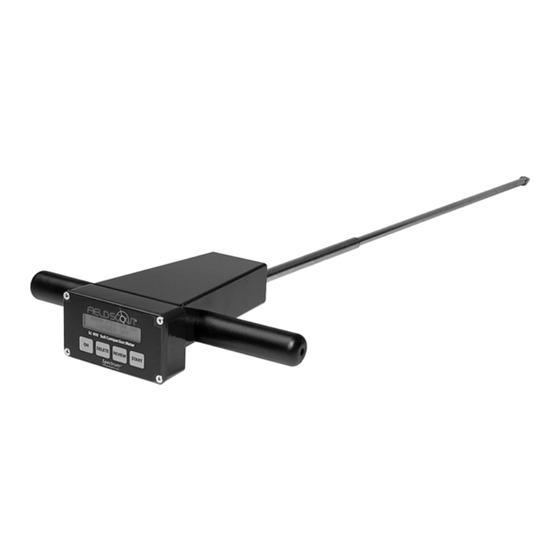
Cone index values are measured by a load cell sensor and can be displayed in PSI or kPa. The Field Scout’s shaft-mounted probe allows the user to easily and rapidly take many measurements. The probe has options for a 1/2” or 3/4” diameter cone tip. The shaft can be dissembled into 2 pieces for easy storage and trans- port. -
Page 4: Taking Compaction Measurements
Measuring soil compaction in dry soil conditions will not yield meaningful results. The SC 900 compaction meter should be used before till- age to determine where the compacted areas of a field/plot are. Once the compacted areas, along with compaction depths, have been determined, a much more effective till- age system can be employed. -
Page 5: Depth Sensor
Depth Sensor ultrasonic sensor located at the base of the meter is used to measure the depth of penetration. The field of view extends about from the shaft. The Depth sensor measures dis- Sensor tance by emitting a sound wave and meas- uring the travel time of the first reflected wave. -
Page 6: Meter Operation
Logger/GPS screens above will be bypassed during startup. The data logger can be activated through the SC 900 software (see Meter Settings, p. 16). If you are using GPS, but the meter doesn’t find the GPS signal when powering up, the meter will not search for the GPS signal when taking readings. - Page 7 For meters with firmware version 8.1 or greater, the final startup screen displays the cone size currently selected. This cone size option can be Use 1/2 in. Cone Change w/ REVIEW changed by pressing the RE- VIEW button. Pressing the Cone Selection Screen START button will transition the meter to the initial operation...
-
Page 8: Measurement Procedure
Measurement Procedure Recording the best quality data requires some practice. Your objective is to uniformly push the probe into the ground using an even motion. The programmed rate, specified in the ASABE standards, is approximately 1 second per 1 inch. If this rate is exceeded, the meter will display a warning message (see Diagnostic Messages p. - Page 9 Geo-Referencing Compaction Measurements To geo-reference your data, you will need to connect a GPS/DGPS unit to the SC 900 and proceed as described above. The GPS format should be NMEA 0183. See Connecting to a GPS Unit (p. 12) for further details.
-
Page 10: Connecting To A Computer
Computer SC 900 data port The data port on the underside of the SC 900 meter (shown above) can be accessed by removing the plastic screw. It is through this port that the meter is connected to either a PC or to a GPS unit. -
Page 11: Identifying The Correct Com Port
Identifying the Correct Com Port T h e c o m p u t e r Communications Port to which the cable is connected identified by using a paper clip. 1. Disconnect the serial cable from the meter. 2. To bring up the Port Selection screen, click on the Com Port Button, select the com port to be tested and click the Port Test button. -
Page 12: Connecting To A Gps Unit
Connecting to a GPS Unit Cable Connections A GPS/DGPS cable (item # 2950CV5) is required to con- nect the SC900 meter to a GPS unit. This cable has a 9- pin male connection and a stereo pin that connects to the meter’s data port. -
Page 13: Calibration/Battery Change
Calibration/ Battery Change Calibration The reading of the meter’s load cell can be recalibrated with the following procedure. Note: During the calibration procedure, care must be taken to ensure that the only force on the load cell is the weight of the meter itself. 1. -
Page 14: Main Toolbar
Select the Com Port that is assigned to the computer data port. See Identifying the Correct Com Port (p. 11) for instructions on how to determine which port to select. Meter Type Select the SC900 option from the list of available Field Scout meters. - Page 15 Download To download data from the internal data logger, turn the meter off and connect the black serial cable to the RS-232 port on the underside of the meter. Click the Download button on the main software screen. In the Save Data As screen, give the file a descriptive name and select the loca- tion where it will be saved.
-
Page 16: Meter Settings
Meter Settings The Meter Settings screen in the Field Scout Soil Com- paction Meter software is used to configure the meter and datalogger for your specific application. This screen can be accessed by clicking on the Meter Set- tings button on the main toolbar screen (see p. 14). - Page 17 checked, the logger will store the GPS value only if it has been differentially corrected. If the differential correction is not found, only the soil compaction values will be stored in the data file. In general, it is recommended to leave this option unchecked.
-
Page 18: Diagnostic Messages
Diagnostic Messages If the meter is unable to successfully measure a soil compaction profile, it will display one of the following warning messages and no data will be sent to the data- logger. In these instances, it may be necessary to with- draw the probe from the soil (if necessary) and hit the START button to continue using the meter (see Meas- urement Procedure p. - Page 19 This error message indicates !! Depth Error !! that the meter missed a depth Hit RVW to Save reading. This can be caused by a momentary, but rapid, insertion of the probe into the soil or by an object such as a foot or a knee suddenly com- ing into the field of view of the sonic depth sensor.
-
Page 20: Data Management
“Logger Started” line. Note: You must have meter firmware v. 8.2 or greater and Field Scout software v. 4.8 or greater to generate the cone size column. -
Page 21: Meter Dimensions
Meter dimensions The following are the dimensions of the SC 900 Soil Compaction Meter. 12” Meter 7.25” 8.5” Shaft Connection 19.75” Cone Tip... -
Page 22: Specifications
Specifications Measurement Cone Index (PSI or kPa) Units Resolution 1” (2.5 cm), 5 PSI (35 kPa) ±0.5” (±1.25 cm), ±15 PSI (±103 kPa) Accuracy Range 0 - 18” (0 - 45 cm), 0 - 1000PSI (0 - 7000 kPa) Maximum 72 in/min (182 cm/min) Insertion Speed * 210 lbs... -
Page 23: Appendix 1: Time Zone Corrections
Appendix 1 Time zone corrections Time Zone City Correction Dublin, Lisbon, London Rio de Janeiro, Montevideo Asuncion Atlanta, Indianapolis, New York, Ottawa, Bogota, Montreal, Toronto Guatemala City, Houston, New Orleans, Chicago, Mexico City, Winnipeg Phoenix, Denver, Edmonton San Francisco, Los Angeles, Vancouver Anchorage Honolulu Wellington... -
Page 24: Appendix 2: When To Replace The Cone
Appendix 2 Determining when to replace the cone Repeated soil sampling will wear down the metal cone, especially in coarse or sandy soils. It is recommended that the diameter of the cone be checked periodically to con- firm that it is within the ASABE spec. The determination as to when to replace the cone will depend on how the user is applying the meter. - Page 25 Depth Target The current versions of the depth targets (item# 6110FST) contain punched holes that are cut to the minimum cone diameter for each cone size. To check the cone diameter, place the meter on the ground, upside down, and try to slide the appropriate-sized wear guide hole over the cone.
- Page 28 R 12/13...
Need help?
Do you have a question about the SC 900 and is the answer not in the manual?
Questions and answers