CS Instruments DS400 mobile Installation And Operating Instructions Manual
Intelligent paperless recorder
Hide thumbs
Also See for DS400 mobile:
- Installation and operating instructions manual (119 pages) ,
- Installation and operating instructions manual (36 pages)

Subscribe to Our Youtube Channel
Related Manuals for CS Instruments DS400 mobile


Summary of Contents for CS Instruments DS400 mobile
- Page 1 EN English Installation and operating instructions intelligent paperless recorder DS400 mobile DS 400 mobile V1.29 Seite 1 von 109...
-
Page 2: Foreword
Foreword I. Foreword Dear customer, thank you very much for deciding in favour of the DS 400. Please read this installation and operation manual carefully before mounting and initiating the device and follow our advice. A riskless operation and a correct functioning of the DS 400 are only guaranteed in case of careful observation of the described instructions and notes Sales Office South / Geschäftsstelle Süd... -
Page 3: Table Of Contents
Table of Contents Table of Contents Foreword ..............Fehler! Textmarke nicht definiert. Table of Contents ......................3 Safety instructions ......................6 Generell ........................... 6 Installation ..........................7 Lithium Ion Battery ........................ 7 Application area ....................... 8 Intended use ........................9 Technical data DS 400 .................... - Page 4 Table of contents Operation DS 400 ......................19 Switching on / off of the DS400 mobile ................19 Main menu (Home) ....................... 19 9.2.1 Initialization ........................19 9.2.2 Main menu after initialization ................... 20 Settings ..........................21 9.3.1 Password-Settings ......................21 9.3.2...
- Page 5 Table of contents 9.3.4 Set backlight ........................66 9.3.5 Cleaning ........................... 67 9.3.6 System-Status ........................67 9.3.7 About DS 400........................67 9.3.8 Virtual Channels (optional) ....................68 Option „Virtual Channels“ activation ................. 68 9.3.8.1 9.3.8.2 Virtual Channels Einstellung..................69 9.3.8.3 Selection of Sensor-type ..................
-
Page 6: Safety Instructions
Regional and national regulations respectively, have to be observed in addition to this instruction manual if necessary. In case of any obscurities or questions with regard to this manual or the instrument please contact CS Instruments GmbH. Warning! Supply voltage! Contact with supply voltage carrying non-insulated parts may cause an electric shock with injury and death. -
Page 7: Installation
European Guideline 2006/66/EC, defective or used battery packs/batteries, must be collected separately and disposed of in an environmentally correct manner. Batteries no longer suitable for use can be directly returned at: CS Instruments GmbH Zindelsteiner Str. 15 D-78052 VS-Tannheim CS Instruments GmbH... -
Page 8: Application Area
Application area Application area Our long-term hands-on experience in measurement and control technology was implemented in the new DS 400. From recording of the measured data, automatic sensor identification, indication on a big colour screen, alerting, storage up to remote read-out via web server, all that is possible with DS 400. By means of the CS-Soft, software alarms can be sent via SMS or e-mail. -
Page 9: Intended Use
Intended use Intended use The DS 400 data logger serves for the stationary measured data acquisition and storage of analogue and digital input signals. The DS 400 data logger is exclusively designed and constructed for the proper application purpose that is described herein and must only be used correspondingly. -
Page 10: Technical Data Ds 400
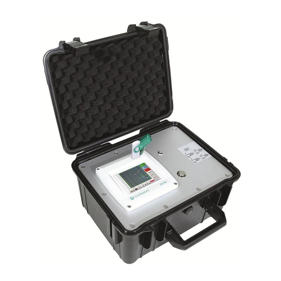
Technical data DS 400 Technical data DS 400 Dimensions of housing 270x225x156 mm Weight 2.2 kg impact resistant HDPE/HWU –plastic (ABS). Case Material (2x2) sensor inputs for analogue and digital sensors freely allocable. Digital CS sensors for dew point and consumption with SDI interface FA/VA 400 Series. -
Page 11: Input Signal
Input Signal Input signal Input signal 0 – 20 mA / 4 – 20 mA Measuring range Current signal Resolution 0,0001 mA (0 – 20 mA / 4 – 20 mA) internal or external 0,03 mA 0,05 % Accuracy power supply 50 ... -
Page 12: Connection Diagrams Of The Different Sensor Types
Connection diagrams of different Sensors Connection diagrams of the different sensor types Connector pin assignment for all sensors A1 – A2, B1 – B2 The interface connector to be used is an ODU Medi-Snap 8 pin – Reference: K11M07-P08LFD0-6550 Available connection cables at CS-Instruments are: ODU with Open ends: Order no 0553 0501, cable length: 5 m. -
Page 13: Connection Diagrams
Connection Diagrams Connection diagrams The following connection diagrams in Chapter 7 apply to A1 to B2! FA serial: dew point sensors from CS Instruments VA serial: consumption sensors from CS Instruments 7.2.1 Anschluss CS Taupunktsensoren Serie FA 415/FA 300 Blau/Blue... -
Page 14: Connection Pulse Sensors
Connection Diagrams 7.2.4 Connection pulse Sensors signal level 0: +24Vdc low = 0 – 0,7 VDC -Vb Gnd Loop signal level 1: high = 2,5 – 30 VDC Loop (+) I 1 = 2.5V – 30V t = 400 µs 0 = 0V –... -
Page 15: Analogue Two-, Three-, And Four-Wire Current Signal
Connection Diagrams 7.2.5 Analogue two-, three-, and four-wire current signal Sensors with 4 - 20 mA output in 2-wire technology Blau/ Blue +24Vdc -Vb Gnd Sensor Loop Loop DS 400 (+) I Gelb / Yellow ß +4 ...20mA PT Gnd (-) V - PT - I (+) V- PT PT Supply... -
Page 16: Three- And Four-Wire Power Supply 0 - 1/10/30 Vdc
Connection Diagrams 7.2.6 Three- and four-wire power supply 0 - 1/10/30 VDC Blau/ Blue +24Vdc Sensor Rot/Red -Vb Gnd Loop Loop Sensor with voltage output in 3-wire technology (+) I PT Gnd (-) V - PT - I Gelb / Yellow (+) V- PT PT Supply Analogboard... -
Page 17: Two-, Three- And Four-Wire Connector Pin Assignments For Pt100/Pt1000/Kty81
Connection Diagrams 7.2.7 Two-, three- and four-wire connector pin assignments for PT100/PT1000/KTY81 +24Vdc -Vb Gnd Loop Loop (+) I 2-wire PT100/PT1000/KTY81 Grau/Grey PT Gnd (-) V - PT - I Gelb / Yellow (+) V- PT PT Supply Rosa / Pink Analogboard +24Vdc -Vb Gnd... -
Page 18: Connect The Ds 400 With A Pc
Connect the DS400 with a PC Connect the DS 400 with a PC Important: The IP addresses of PC and DS 400 must be statically assigned (DHCP off) and have to be in the same network. If the IP-address of the DS 400 has changed, you have to reboot! Remark: IP-address of the DS 400: See chapter, 9.3.3.3 Network-Settings... -
Page 19: Operation Ds 400
Switching on / off of the DS400 mobile To switch on / off the DS400 mobile you have to press ( >= 3sec) the on / off knob. A short press of the on / off knob during operation opens a popup with indication of the remaining operation time. -
Page 20: Main Menu After Initialization
Main menu 9.2.2 Main menu after initialization Hard- and Status interval data logger and Date & Time Software-Version Alarm display Datalogger remaining memory capacity Important: Before the first sensor setting is made, the language and time should be set! Remark: Language Chapter 9.3.3.1... -
Page 21: Settings
Settings / Password-Settings Settings The settings are all protected by a password! Settings or changes are generally confirmed with OK! Remark: If you go back to main menu and then again one of the setting menus is called, you must enter the password again. -
Page 22: Sensor-Settings
Sensor-Settings 9.3.2 Sensor-Settings Important: Sensors from CS Instruments are generally pre-configured and can be connected directly to a free sensor channel! Main menu Settings Sensor settings An overview of the available channels appears after entering the password. Depending on the version 2 or 4 channels. -
Page 23: Choice Of The Sensor Type (For Example Type Cs-Digital Sensor)
Sensor-Settings 9.3.2.1 Choice of the sensor type (For example type CS-Digital sensor) Main menu Settings Sensor settings A1 If still no sensor has been configured, the Type No Sensor appears. By pushing the description field Type No Sensor the list of sensor types appears (see next step). -
Page 24: Name The Measurement Data And Define The Decimal Places
Sensor-Settings / name and recording of measurement data 9.3.2.2 Name the measurement data and define the decimal places Remark: Resolution of the decimal places, the Short Name Value Name are found under the Tool button! Tool Button: Main menu Settings Sensor settings A1 Tool Button For the recorded Value there can be... -
Page 25: Alarm-Settings
9.3.2.4 Alarm-Settings Remark: For DS400 mobile only the alarm-overview is displayed, alarm relays are not accessible.. Main menu Settings Sensor settings A1 Alarm-Button By pushing an alarm button, the following window appears: In the alarm settings an... - Page 26 Sensor-Settings / Alarm-Settings Main menu Settings Sensor settings A1 Alarm-Button Setup Delay The delays (T1 to T4) are free definable but are common valid for all relays. Main menu Settings Sensor settings A1 Alarm-Button description field Delay T1 By changing the text field values the new delay time could be defined.
-
Page 27: More Settings (Scale Analogue Output)
Sensor-Settings / More Settings (scale analogue output) 9.3.2.5 More Settings (scale analogue output) Main menu Settings Sensor settings A1 arrow right (2.page) More settings In More-Settings, you can define whether the 4 - 20 mA analogue output of the sensor m³/h m³/h 293.0... -
Page 28: Dew Point Sensor Fa 400 / Fa 410 Of Type Cs-Digital (Sdi Bus)
Sensor-Settings / Dew point sensor Typ CS-Digital 9.3.2.6 Dew Point Sensor FA 400 / FA 410 of type CS-Digital (SDI Bus) First step: choose an unused sensor channel Main menu Settings Sensor settings A1 Second step: choose type CS-Digital (inserted Digital board for A1/A2) Main menu ... -
Page 29: Flow Sensor Va 400 / Va 420 Of Type Cs-Digital (Sdi Bus)
Sensor-Settings / Dew point sensor Typ CS-Digital 9.3.2.7 Flow sensor VA 400 / VA 420 of type CS-Digital (SDI Bus) First step: choose an unused sensor channel Main menu Settings Sensor settings A1 Second step: choose type CS-Digital (inserted Digital board for A1/A2) Main menu ... - Page 30 Sensor-Settings / Dew Point sensor Type CS-Digital Main menu Settings Sensor settings A1 arrow right (2.page) 100.00 0.000 ltr/min 1000.00 2345678 0.00 20.00 By entering the white text fields the value could be added or changed content could be change Main menu ...
- Page 31 Sensor-Settings / Dew Point sensor Type CS-Digital Main menu Settings Sensor settings A1 arrow right (2.page) Gas Constant description field Air-1 A preset selection of suitable Constants. Remark: After confirm with OK, the font is black again and the values and settings are accepted. Attention: Reference temperature and reference pressure (factory setting 20 °C, 1000 hPa): All volume flow values (m³/h) and consumption values indicated in the display are...
-
Page 32: Dew Point Sensor Fa 500 / Fa 510 Of Type Fa 5Xx (Rs 485 Modbus)
Sensor-Settings / Dew point sensor Type FA 5xx 9.3.2.8 Dew Point Sensor FA 500 / FA 510 of type FA 5xx (RS 485 Modbus) First step: choose an unused sensor digital channel Main menu Settings Sensor settings A1 Second step: choose type FA 5xx (inserted Digital board for A1/A2) Main menu ... -
Page 33: Settings Dew Point Sensor Fa 500 Fa 510
Sensor-Settings / Dew point sensor Type FA 5xx 9.3.2.8.1 Settings Dew point sensor FA 500 FA 510 9.3.2.8.1.1 Unit selection for temperature and humidity Main menu Settings Sensor settings A1 arrow right (2.page) Unit selection for temperature and humidity by pressing the button °C, °F, g/m³... -
Page 34: Definition Of Reference Pressure (Absolute Pressure Value)
Sensor-Settings / Dew point sensor Type FA 5xx Main menu Settings Sensor settings A1 arrow right (2.page)Pressure Setting Sensor By using an ext. pressure sensor, which is detected automatically e.g. here at input B1, the button Sensor has to be activated. -
Page 35: Calibration
Sensor-Settings / Dew point sensor Type FA 5xx 9.3.2.8.4 Calibration Main menu Settings Sensor settings A1 arrow right (2.page) Calibration Here, a one-point calibration can be performed. 26.45 For that purpose, please enter in the text box "Reference Value"... -
Page 36: Flow Sensor Of Type Va 5Xx (Rs 485 Modbus)
Sensor - Settings / Flow sensor Type VA 5xx 9.3.2.9 Flow sensor of type VA 5xx (RS 485 Modbus) First step: choose an unused sensor digital channel Main menu Settings Sensor settings A1 Second step: choose type VA 5xx (inserted Digitalboard for A1/A2) Main menu ... -
Page 37: Settings For Flow Sensor Va 5Xx
Sensor - Settings / Flow sensor Type VA 5xx 9.3.2.9.1 Settings for Flow sensor VA 5xx Main menu Settings Sensor settings A1 arrow right (2.page) For each text field could be the either a value or a unit be set. Settings by entering the text field and then input a value or select the unit for the appropriate field. -
Page 38: Gas Constant Settings
Sensor - Settings / Flow sensor Type VA 5xx 9.3.2.9.1.2 Gas Constant settings Main menu Settings Sensor settings A1 arrow right (2.page) Gas Constant description field All gases marked in blue and with (real) have been a real gas calibration curve stored in the sensor. -
Page 39: Definition Of The Reference Conditions
Sensor - Settings / Flow sensor Type VA 5xx 9.3.2.9.1.3 Definition of the reference conditions Here, the desired measured media reference conditions for pressure and temperature can be defined Main menu Settings Sensor settings A1 arrow right (2.page) Ref. Pressure description field Main menu ... -
Page 40: Definition Consumption Counter Value And Consumption Unit
Sensor - Settings / Flow sensor Type VA 5xx 9.3.2.9.1.5 Definition consumption counter value and consumption unit Main menu Settings Sensor settings A1 arrow right (2.page) Count Val. description Field Main menu Settings Sensor settings A1 arrow right (2.page) Count Val. Unit description Field The sensor allows taking over a starting counter value. -
Page 41: Settings Analogue Output 4-20Ma Of Va 5Xx
Sensor - Settings / Flow sensor Type VA 5xx 9.3.2.9.1.6 Settings analogue output 4-20mA of VA 5xx Main menu Settings Sensor settings A1 arrow right (2.page) More-Settings 4-20mA Ch1 This menu allows the adjustment / assignment of the measurement value and the scaling of the analogue output the”4-20mA Ch1”... -
Page 42: Settings Pulse / Alarm Output Of Va 5Xx
Sensor - Settings / Flow sensor Type VA 5xx 9.3.2.9.2 Settings Pulse / Alarm output of VA 5xx Main menu Settings Sensor settings A1 arrow right (2.page) More-Settings Pulse / Alarm The pulse output of the VA 5xx could be set functionally as pulse output or alarm output. - Page 43 Sensor - Settings / Flow sensor Type VA 5xx Main menu Settings Sensor settings A1 arrow right (2.page) More-Settings Alarm In case of use the pulse output as alarm following definitions needs to be set: “unit”...
-
Page 44: Settings Zeropoint Or Low Flow Cut Off For Va 5Xx
Sensor - Settings / Flow sensor Type VA 5xx 9.3.2.9.3 Settings ZeroPoint or Low Flow Cut off for VA 5xx Main menu Settings Sensor settings A1 arrow right (2.page) More-Settings Zeropoint With these function following adjustments for the sensor VA 5xx could be done: 2.045 Zeropoint:... -
Page 45: Configuration Of Analogue-Sensors
Sensor-settings / Configuration of Analogue-Sensors 9.3.2.10 Configuration of Analogue-Sensors Applicable only at DS 400 variants with an analogue board equipped. A brief overview of the possible Type of settings with examples. Except CS-Digital, see chapter 9.3.2.1 Choice of the sensor types (For example type CS-Digital sensor) 9.3.2.6 Dewpoint sensor with type CS-Digital. - Page 46 Sensor-settings / Configuration of Analogue-Sensors Main menu Settings Sensor settings B1 arrow right (2.page) description field Unit A preset selection of suitable units by Type 0 - 1/10/30 V 0/4...20 The different pages could be displayed by pressing the Page-button.
-
Page 47: Type Pt100X And Kty81
Sensor-settings / Configuration of Analogue-Sensors 9.3.2.10.2 Type PT100x and KTY81 Main menu Settings Sensor settings B1 Type description field PT100x Measure 2 Here the sensor type PT100 and the Unit 35.55 °C °C are chosen, alternatively the sensor types PT1000 and KTY81, as well as the Unit... -
Page 48: Type Pulse (Pulse Ration)
Sensor-settings / Configuration of Analogue-Sensors 9.3.2.10.3 Type Pulse (Pulse ration) Main menu Settings Sensor settings B1 Type description field Type description field Pulse Typically the value with unit of 1 Pulse standing on the sensor and can directly entered to the 1 Pulse = description field. - Page 49 Sensor-settings / Configuration of Analogue-Sensors Main menu Settings Sensor settings B1 arrow right (2.page) Unit Consumption m³/h Unit of current Consumption Type Pulse m³/h m³/min Remark: Example with the unit cubic meters / hour. Main menu Settings Sensor settings B1 arrow right (2.page) Unit Counter The available Units for the Unit Counter...
-
Page 50: Type „No Sensor
Sensor-settings / Type „No Sensor“ 9.3.2.10.4 Type „No Sensor“ Main menu Settings Sensor settings A2 Type description field No Sensor Is used to declare a not currently needed channel as No Sensor defined. If you go to Type No Sensor Back, channels will appear as unused. -
Page 51: Type Modbus
Sensor-settings / Type „Modbus“ 9.3.2.11 Type Modbus 9.3.2.11.1 Selection and activation of Sensor-Type Modbus First Step: First step: choose an unused sensor channel Main menu Settings Sensor settings A1 Second step: choose type Modbus Main menu Settings Sensor settings A1 Type description field Modbus Third step: confirm with Main menu ... - Page 52 Sensor-settings / Type “Modbus” Main menu Settings Sensor settings A1 Reg. Address description field The measurement values are kept in the registers of the sensor and can be addressed via Modbus and read by the DS400 This requires setting the desired register addresses in the DS400.
- Page 53 Sensor-settings / Type “Modbus” Example : Holding Register - UI1(8b) - Zahlenwert: 18 Selection Register Type Holding Register, Data Type U1(8b) und Byte Order A / B HByte LByte 18 => Data Order 1. Byte 2. Byte Holding Register – UI4(32) - Value: 29235175522 à AE41 5652 Selection Register Type Holding Register,...
- Page 54 Sensor-settings / Type “Modbus” Main menu Settings Sensor settings A1 Scale- description field The use of this factor allows adapting the output value by the same. By default or value = 0 no scaling is applied don’t scale and displayed in the field is Main menu ...
-
Page 55: Custom Sensor
Custom Sensor 9.3.2.12 Custom Sensor With regular use of different sensors or sensor settings it is possible, based on a basic sensors a so called predefined sensors-settings (Custom Sensor) to save and to read it back. Stored are all settings of the sensor except recording button and alarm sett ings.. -
Page 56: Sensor Settings Import
Custom Sensor 9.3.2.12.2 Sensor settings import Main menu Settings Sensor Settings A1 Type Textfield Custom Sensor All already saved sensor settings will be displayed, depending on the location SdCard selected. Changing of the location by pressing button SdCard Then select the required sensor-setting file and confirm it with... -
Page 57: Device Settings
Device-Settings / Language 9.3.3 Device Settings Main menu Settings Device settings Overview of Device settings 9.3.3.1 Language Main menu Settings Device settings Set language Here you can select one of 10 languages for the DS 400. DS 400 mobile V1.29 Seite 57 von 109... -
Page 58: Date & Time
Device-Settings / Date & Time 9.3.3.2 Date & Time Main menu Settings Device settings Date & Time By pushing the Time Zone description field and enter the correct UTC, you can set the correct time all over the world. The summer and wintertime switchover is realized by pushing the Daylight Saving... -
Page 59: Network-Settings
Device-Settings / Network-Settings 9.3.3.3 Network-Settings Main menu Settings Device settings Network-Settings Here you can set up and made a connection, with or without DHCP, to a computer. Remark: With activated DHCP (green hook), the automatic integration of the DS 400 in an existing network is possible, without a manual configuration. -
Page 60: Relay Settings
Device-Settings (Relay settings) 9.3.3.4 Relay Settings Remark: Alarm relays are not accessible at DS 400 mobile, popup information only. Main menu Settings Device settings Relais-Settings By activated relais button it is allowed / possible to turn off the corresponding alarm relays in the popup appearing in alarm case. -
Page 61: Sd-Card
Device-Settings / SD-Card 9.3.3.5 SD-Card Main menu Settings Device settings SD-Card Reset Logger Database Main menu Settings Device settings SD-Card Erase SdCard By pressing Reset Logger Database all actual stored data on SD-Card will be blocked for use in DS 400. -
Page 62: System
System 9.3.3.6 System Overview of the System features 9.3.3.6.1 Save system settings Important: Before updating the DS 400 the system settings should be secured either on a USB or the internal SD-Card! Home Import / Export Export System Settings With Export system settings, all existing sensor settings can be exported to a USB stick or to the internal SD card. -
Page 63: System Update
System / System update 9.3.3.6.2 System update Important! System update can only be done with power supply connected to ensure there is a continuous power supply during the update. Home Settings Device settings System-Update Overview of System-Update-Functions. 9.3.3.6.3 Check for Updates Home ... -
Page 64: Update Firmware
System / System update 9.3.3.6.4 Update Firmware Home Settings Device settings System-Update Update-Firmware The update of DS 400 for all new SW parts starts. Important: If the Reboot system button appears after the update, it must be pushed to restart the DS 400! 9.3.3.6.5 Update Channels Home ... -
Page 65: Factory Reset
System / Factory reset 9.3.3.6.6 Factory Reset Main menu Settings Device settings System Reset to Defaults Reboot System here, if you need it! DS 400 mobile V1.29 Seite 65 von 109... -
Page 66: Calibrate Touch-Screen
Device Settings / Calibrate touchscreen / Set backlight 9.3.3.7 Calibrate touch-screen Main menu Settings Device settings calibrate touchscreen If necessary, the touch-screen calibration can be changed here. Push Calibrate and it appears, 1. left above,2. bottom right, 3. bottom left, 4.right above and 5. -
Page 67: Cleaning
Device Settings / Cleaning / System Status 9.3.5 Cleaning Main menu Settings Cleaning This function can be used for cleaning the touch panel during running measurements. If one minute is not enough time to clean, the process can be repeated at any time. Is the cleaning faster finished, then you can push the to abort press long... -
Page 68: Virtual Channels (Optional)
Virtual Channels 9.3.8 Virtual Channels (optional) The option „Virtual Channels“ offers 4 additional channels (no HW Channels) where it is possible to display calculations of each single HW-Channel, virtual channels and free defined constants as well. For each „Virtual Channel“ are 8 calculations each with of 3 operands and 2 operations possible. Possible cases are calculation of: ... -
Page 69: Virtual Channels Einstellung
Virtual Channels 9.3.8.2 Virtual Channels Einstellung Main menu Settings Sensor Settings Virtual Channels After pushing the button „Virtual Channels“ in the Sensor Settings menu an overview with the 4 available “Virtual Channels” is displayed. Remark: By default, all channels are without settings. 9.3.8.3 Selection of Sensor-type Main menu ... -
Page 70: Configuration Of Each Single Virtual Value
Virtual Channels Main menu Settings Sensor Settings Virtual Channels V1 Name description field By pushing the Text field Name a Sensor name could be inserted. 9.3.8.4 Configuration of each single virtual value Each virtual channel includes 8 individual calculated values where every value has to be activated separately. -
Page 71: Definition Of Operands
Virtual Channels 9.3.8.4.2 Definition of Operands Main menu Settings Sensor Settings Virtual Channels V1 arrow right(2.page) 1stOperand By accessing the text field 1st Operand The list with all channels (HW and virtual channels) and const. Value appears. Main menu ... -
Page 72: Definition Of Operations
Virtual Channels 9.3.8.4.3 Definition of Operations Main menu Settings Sensor Settings Virtual Channels V1 arrow right (2.page) 1st Operation By accessing the text field 1st Operation the list with all available operands appears. Selecting and validation of the operand by pressing the respective operand. - Page 73 Virtual Channels By pressing the button Edit you enter the menu for inserting the new Unit. Then define the unit and confirm it with the button ß With the buttons it is possible to correct the input. ß Button deletes the last figure Button clears the whole field Important...
-
Page 74: Value Name, Resolution Of Decimal Places And Recording Of Values
Virtual Channels 9.3.8.5 Value name, resolution of decimal places and recording of values Main menu Settings Sensor Settings Virtual Channels V1 Tool-Button Resolution of the decimal places, the Short Name Value Name are found under the Tool button For the recorded Value... -
Page 75: Calculation Example „Specific Performance
Virtual Channels Calculation Example „Specific Performance“ 9.3.8.6 As an example we assume a compressor system with 3 single compressors. The consumption measurements are done with consumption sensors VA400 at the inputs A1 – B1 & and an electric meter at input B2. VA400 [m³] Energy VA400 [m³]... - Page 76 Virtual Channels Result in is the energy consumption read out from the energy counter. V1a à complete Air consumption 66090.2 m³ V1b à energy consumption 4720.75 kWh Calculation of the specific. Perfor. Is done in with For this example, it is 0,072 KWh/m³ Calculation of energy cost complete in with * 0.21.
-
Page 77: Analog Total (Optional)
Analog-Total 9.3.9 Analog Total (optional) The Option „Analog Total“ offers the possibility of a consumption measurement also for sensors with analogue outputs e.g.: 0-1/10/30V and 0/4 – 20mA. Option „Analog Total“ activation 9.3.9.1 After purchasing of the option „Analog Total“ the functionality has to be activated first. Main menu ... -
Page 78: Selection Of Sensor Type
Analog Total 9.3.9.2 Selection of sensor type See also chapter 9.3.2.10 Configuration of analogue sensors Main menu Settings Sensor Settings B1 If still no sensor has been configured, the Type No Sensor appears. By pushing the description field Type No Sensor the list of sensor types appears (see... -
Page 79: Webserver (Optional)
Webserver 9.3.10 Webserver (optional) With the web server you have access, worldwide, to the DS 400 system information, the measurement data, the possibility to start the logger and also to install an e-mail notification in case of measurement exceedances (alarms). The individual functions are accessible via different user levels, every level is protected. -
Page 80: Setup The Webserver Admin Password
Webserver 9.3.10.2 Setup the Webserver Admin Password The setup of the Web Admin password is done under Home Settings Device Settings Network Settings In the text description field WebAdmin Password could the password be set up. The password length is >=8 characters. Takeover by pressing Apply &... -
Page 81: Webserver Assignment Of Rights (Administrator)
Webserver 9.3.10.4 Webserver assignment of rights (Administrator) 9.3.10.4.1 Accessrights Webserver For individual functions, appropriate privileges are required, see table "access rights" Rights Settings Info Status Actuals Chart MailonAlarm Group User/Mail Guest User Operator Admin Table Accessrights 9.3.10.5 Webserver Login After pressing the Button « Login » following screen is visible. Logion as Administrator with Username «admin»... -
Page 82: New Users And Password
Webserver 9.3.10.6 New users and password Selection of function « User/Passw. » (only for Administrators accessible) With this function you are able to define the users with their corresponding accessrights. Username : min. 4 characters; max. 12 characters Password : min. -
Page 83: Webserver E-Mail Configuration (Administrator)
Webserver 9.3.10.7 Webserver E-Mail Configuration (Administrator) Access of function « EMail » only for administrators In case you are not logged in as administrator, please see chapter 9.3.10.5 At the first/ initial configuration there are no entries. An existing mail account and those acessdata are needed for final mail configuratuion. from: mail username to rcp 1:... -
Page 84: Webserver Mailonalarm (Administrator & Operator)
Webserver 9.3.10.8 Webserver MailOnAlarm (Administrator & Operator) This feature allows sending an e mail at limit violations (alarms) to the addresses defined under EMail. Mail deliveries are based on the respective Alarm relays, i.e. when limits are exceeded and the relays are activated an E-mail will be sent too. -
Page 85: Webserver Chart (Administrator, Operator & User)
Webserver 9.3.10.9 Webserver Chart (Administrator, Operator & User) With these function it is possible to access and view all measurement data stored on the DS500 SD card. The data are by a continuous recording, on a daily base, else according the used recording period stored. -
Page 86: Webserver Screen
Webserver 9.3.10.10 Webserver Screen Herewith it is possible to get a screen copy of the DS400 for Home menu, Chart/RT, Channels, Realtime values, Alarm and Settings (System status, about DS 400). Remark : Any selection change done through the webserver is transferred to the DS 400 too. With simultaneous access to the DS 400 by webserver and an operator direct at the DS400 the operator has priority. -
Page 87: Webserver Actuals
Webserver 9.3.10.11 Webserver Actuals show Sensor: enable / disable the view for individual sensors show values: enable / disable the view for individual sensors values Refresh time: Selection of the timespan of the data update (60s, 30s, 10s, 5s, 2s,1s) Font size: Size of characters (4 different sizes) 9.3.10.12 Webserver Status... -
Page 88: Data Logger (Optional)
Data Logger 9.3.11 Data Logger (optional) After purchasing of the option „Data logger“ the functionality has to be activated first. 9.3.11.1 Option „Data Logger“ activation Main menu Settings about DS 400 40130024 for „Data logger“ Please push the button 1.21 and you will requested to insert the key-code 3.02... - Page 89 Data Logger A different, individual Time interval can be entered in the highlighted white description field right at the head, where the currently set Time interval is always displayed. Remark: The largest possible Time interval is 300 seconds. Remark: If more than 12 measurement data are recorded at the same time, the smallest possible time interval of the data logger is 2 seconds.
- Page 90 Data Logger Main menu Settings Logger settings timed Start button By pushing the timed Start button and then the date/time description field below, the date and the start time can be set for a data logger recording. Remark: If the start time is activated, it will automatically be set at the current time plus...
- Page 91 Data Logger Main menu Settings Logger settings timed Start button/timed Stop button Date/Time description field Cal button With the button, the desired date can be easily select from the calendar. Main menu Settings Logger settings Start button After the start and stop time activation and the created settings, the Start...
-
Page 92: Chart
Chart Chart Main menu Chart Attention: In the Chart there can be represented only records that have already finished! Current records can be seen in Chart/Real time values. (See chapter 12.4 Chart/Real time values) Running measurement, there are no values represented! Zoom and scroll options in the time domain of the Chart: Maximal an entire day can be represented (24h). - Page 93 Chart Main menu Chart Date description field By pushing the date description field (center bottom) the calendar, from which the appropriate date can be selected conveniently, appears. Stored measuring data can be select here time (START and STOP), Comment File name (contains English date).
- Page 94 Chart Main menu Chart Setup Unit description field m³/h Select the Unit of the represented recording m³/h from the menu. Main menu Chart Now, the grid can be set with min, max, and m³/h step. By pushing the A.Scale-button a calculated auto-scaling will be defined.
- Page 95 Chart Main menu Chart DS 400 mobile V1.29 Seite 95 von 109...
-
Page 96: Chart / Real Time Values
Channels Chart / Real time values Main menu Chart/Real time values One or more channels for the recording and presentation of measured data can be selected here, such as a dew point sensor or several different sensors. After pushing this button currently recorded measurement data in the current time range are represented. - Page 97 Chart / Real time values Main menu Chart/Real time values m³/h 1350 Channel A1: m³/h Elected the flow as Chart If several channels are logged, all charts will be displayed, but there is only the y-axis of the selected channel visible. If there is no grid entered in the setup, will be 0,...
-
Page 98: Channels
Channels Channels Main menu Channels The overview of Real time values shows the current measured values of all connected sensors. Exceeds or falls below the set alarm limits, the respective measured value flashes yellow (alarm 1) or red (alarm Main menu ... -
Page 99: Real Time Values
Real time values Real time values Main menu Real time values The view Real time values allows to display of 1145,55 1 to 5 free definable measurement values. m³/h By exceeding the upper- or lower alarm levels the respective measurement value flashes yellow for Alarm-1 or red for Alarm-2. -
Page 100: Alarm-Overview
Alarm Overview Alarm-Overview Main menu Alarm-Overview In the Alarm overview, you can immediately see whether there is an alarm 1 alarm You can see also in other menu items: Main Real time values Main Settings Sensor settings The channel name will appear yellow invers (alarm 1) or inverse red... -
Page 101: Export /Import
Export / Import Export /Import 9.9.1 Export Logger data Recorded data can be transferred to a USB stick, by using Export/ Import. Main menu Export / ImportExport Logger data With Export Logger data, Export Screenshots Export system settings the recorded measurement data, screenshots and saved settings can be transferred to a USB stick. - Page 102 Export / Import If there have been recorded several measurements on the same date, they appear after the date selection with OK. Now a recording can be selected comfortable. Main menu Export/Import Export Logger data export The measurement data of the selected period are exported to a USB stick. DS 400 mobile V1.29 Seite 102 von 109...
-
Page 103: Export System Settings
Export / Import 9.9.2 Export System Settings Using this function, all existing device- and sensor settings can be exported to a USB stick or SD-card. All sensor settings including recording-, alarm-, measurement resolution-, graphics-, current values and naming-definitions are taken over. Main menu ... -
Page 104: Import System Settings
Export / Import 9.9.3 Import System Settings Using this function, stored system settings can be read back again. All sensor settings including recording-, alarm-, measurement resolution-, graphics-, current values- and naming-definitions are taken over. Main menu Export/Import Import system settings Depending on the selected location, USB stick or internal SD-card, all already stored settings will be listed. -
Page 105: Screenshot Function
Screenshot function 9.10 Screenshot function This function allows you to store a copy of the screen of the menus Chart, Chart / Real time Values, Channels and Real time Values to a USB-Stick or SD-Card. Mainly foreseen to save not logged data. 9.10.1 Screenshot saving Main menu ... -
Page 106: Screenshots Export
Export / Import 9.10.2 Screenshots export The screenshots stored on the SD card can be exported to a USB stick Main menu Export / Import With Export Screenshots the recorded screenshots data can be transferred to a USB stick. Main menu ... - Page 107 Export / Import Main menu Export / Import Export Screenshots Export The screenshots of the selected period are exported to a USB stick. DS 400 mobile V1.29 Seite 107 von 109...
-
Page 108: Cleaning
Cleaning Cleaning Note: The DS 400 has a cleaning-function which protects the display against unintentional operation in the event of cleaning measures. Please refer to Chapter 9.3.5 for further information. Cleaning of the DS 400 must be undertaken using a slightly damp (not wet) cotton cloth or one-way wipe, and mild, commercially available cleaner/soap. -
Page 109: Seite 4 Von
DS 400 mobile V1.29 Seite 109 von 109...
Need help?
Do you have a question about the DS400 mobile and is the answer not in the manual?
Questions and answers