Table of Contents
Advertisement
EBC30 3002180 100315
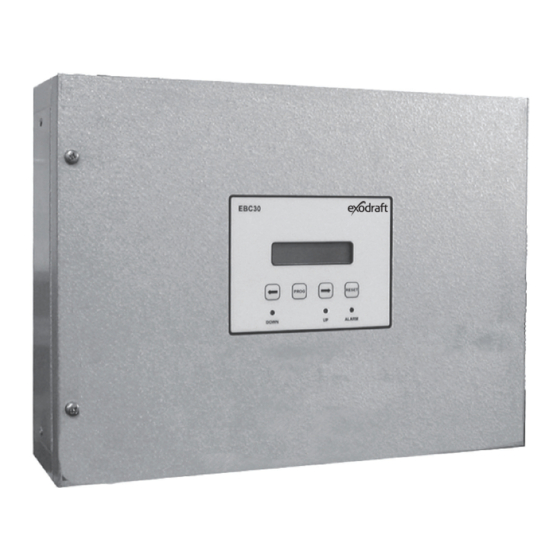
EBC30
READ AND SAVE THESE INSTRUCTIONS!
Product information
Mechanical installation
Electrical installation
Start up and configuration
Maintenance and troubleshooting
Job name: _________________________________
Installer: __________________________________
Installation date: ___________________________
Distributor contact information:
ENERVEX Inc. • T: 800.255.2923
info@enervex.com • www.enervex.com
Installation and operation manual
Chapters 1 + 2
Chapter 3
Chapter 4
Chapter 5
Chapter 6
USA
CAN
Advertisement
Table of Contents

Related Manuals for Exodraft EBC30


Summary of Contents for Exodraft EBC30
- Page 1 Installation and operation manual EBC30 3002180 100315 EBC30 READ AND SAVE THESE INSTRUCTIONS! Product information Chapters 1 + 2 Mechanical installation Chapter 3 Electrical installation Chapter 4 Start up and configuration Chapter 5 Maintenance and troubleshooting Chapter 6 Job name: _________________________________...
-
Page 2: Table Of Contents
1.4 EBC30 control components ........ -
Page 3: Function
• duct pressure in dryer venting systems • duct pressure in ventilation systems. The EBC30 can simultaneously control an exhaust fan, an intake fan or a draft damper. Any two of these can be controlled simultaneously or they can be controlled individually. -
Page 4: Warranty
1.4 EBC30 control components The EBC30 control is built up around a main board that controls all basic functions. In addition, a Triac board and a relay board, are available for special functions. The main board controls draft/exhaust and air supply/ intake functions. It can provide 0-10 V DC signals for Variable Frequency Drives (VFDs), an actuator or other devices accepting a 0-10 V DC control signal. -
Page 5: Dimensions And Capacities
EBC30 3002180 100315 2. Specifications 2.1 Dimensions and capacities exodraft EBC30 control Power supply 1 x 120 V AC Amperage Operating temperature °F/°C -4 to 122/-20 to 50 Range of operation inWC/Pa 0-0.6/0-150 Tolerance inWC/Pa 0.01/3 +/-10 % Control signal max. -
Page 6: Location
EBC30 3002180 100315 3. Mechanical installation 3.1 Location The control and the transducer must be installed inside, preferably in the mechanical room (boiler room). The control does not need to be installed in an enclosure. Fig. 3 shows how the components are connected. -
Page 7: Mounting Of Transducer
EBC30 3002180 100315 3.3 Mounting of transducer Attention must be paid to the position and location of the transducer. Fig. 5 shows the required position. Failure to follow this instruction may result in an inoperable system. An Ashcroft XTP-sensor used for sensing draft should be mounted within six (6) feet of the stack probe. -
Page 8: Installation Of Outdoor Pressure Probe (If Applicable)
EBC30 3002180 100315 3.5 Installation of outdoor pressure probe (if applicable) The outdoor pressure probe should be mounted in a location as free as possible from rooftop obstructions. The choice of location should also consider routing of silicone tubing into the building to minimize tubing run on the roof. -
Page 9: General
NOTE EBC30 is designed for 1 x 120 V AC power supply only. Fan output is regulating on the neutral side and can- not be connected to other circuits. The terminals are connected as shown (for additional information go to chapter 5.1):... -
Page 10: Relay Board Connections
EBC30 3002180 100315 4.2 Relay board connections If the optional Relay Board is used, the control can handle up to 10 appliances. Connect the multi plug from the add-on board to the main board as show below in Fig. 10. -
Page 11: Wiring Of Ashcroft Xtp Sensor
The Ashcroft XTP sensor is wired as shown below. The wiring to the Ashcroft XTP sensor is always the same, while the wir- ing on the EBC30 control depends on whether it is to be wired for exhaust or intake operation:... -
Page 12: Sequence Of Operation
0-10 V DC signal back to the XTP1 (exhaust) or XTP2 (intake) terminals. The current pressure reading is displayed on the EBC30. It displays INT or EXH then the pressure reading or both if the application is Intake and Exhaust. -
Page 13: Pre-Operation Inspection
Continuous operation For continuous operation, Dip Switch 1 & 2 on the back of the display card on the EBC30 door must be in the up/on posi- tion. AUX INPUT connections are not used since the Control always attempts to maintain the pressure set point regardless of appliance status. -
Page 14: Initiation Of Control
EBC30 3002180 100315 5.4 Initiation of control When power is supplied to the control it will go through a start-up procedure to detect and check all components and ap- pliances installed. During this procedure the display will show the following: SOFTWARE VERSION 2.12... - Page 15 EBC30 3002180 100315 Q2 EXHAUST OPERATING MODE The control can operate the fan(s) in either ‘continuous’ or ‘intermittent’ mode. The mode can be changed via the display. The display only shows the chosen mode. The mode can be overridden by the dip switches inside the cover on the print board.
-
Page 16: Detailed Control Programming
To access the Quick-Menu, press the PROG key for 3 seconds. The figure on page 16 shows the sequence of programming. 5.6 Detailed control programming The EBC30 control has a detailed sub-menu for individual parameter settings. See page 19 for more details on parameters and programming. -
Page 17: Programming Sequence
EBC30 3002180 100315 5.7 Programming sequence NOTES Press key for 3 seconds PROG to access menu The pressure can be set Q1 SET EXHAUST Q1 SET EXHAUST PROG PROG * 0.01 inWC between 0.012 and 0.596 * 0.01 inWC (Default is 0.012) Available selections are: "continuous"... - Page 18 EBC30 3002180 100315 6. Maintenance and troubleshooting Most terminal connections are monitored for proper operation. LED lights indicate operating status. If a light is lit, it indi- cates everything is functioning properly while a light out indicates a problem on the circuit it monitors. In addition, fault codes are shown on the display.
-
Page 19: Ebc30 Factory Settings
EBC30 3002180 100315 6.1 EBC30 Factory settings Menu Sub-menu function Display Range Default exhaust EXHAUST draft set point SET EXHAUST 3%-95% of sensor range 0.100 operation mode OPERATION Continuous/Intermittent Intermittent pre-purge PREPURGE time TIME 0-1800 operation mode SPEED MODE Variable/FIX 20 %-100 %... - Page 20 Q3 EXHAUST Pre-purge ___________________________________ seconds Q4 EXHAUST Post-purge ___________________________________ seconds Q5 INTAKE setting ______________________________________ “WC Q6 INTAKE Operating Mode Continuous/Intermittent (circle one) Q7 INTAKE Pre-purge ___________________________________ seconds Q8 INTAKE Post-purge ___________________________________ seconds Q9 ROTATION CHECK Yes No (circle one) www.exodraft.com...
Need help?
Do you have a question about the EBC30 and is the answer not in the manual?
Questions and answers