Table of Contents
Advertisement
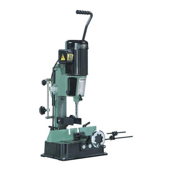
SETUP & OPERATION MANUAL
FEATURES
Heavy duty cast-iron head, column and
base built for steady vibration free per-
formance.
Head slides on precision machined cast-
iron dovetail ways - stroke is controlled by
a gas head-cylinder for smooth operation.
Head tilts up to 30° left or right for angled
mortising, and pivots up to 180° for off
table mortising.
Adjustable head height extends working
capacity by up to 3" (up to 9" under chis-
el), to accommodate work with taller work-
pieces.
Equipped with easy to adjust dual depth
stop for complete control of both down
stroke depth and upstroke travel.
Large feed handle with extra long, multi-
position arm for better leverage and
increased feed control.
Includes an adjustable workpiece stop,
handwheel controlled clamp and a col-
umn mounted hold-down.
Totally enclosed fan cooled (T.E.F.C.) motor
with start capacitor for smooth start-up
and longer running life.
Dust protected on/off switch.
Includes adapter bushings to accommo-
date both 5/8" and 3/4" sized chisel
shanks.
SPECIFICATIONS
CHISEL CAPACITY
1⁄4" TO 5⁄8" (6 TO 16 MM)
MAXIMUM CHISEL STROKE
9" (228 MM)
DISTANCE FROM FENCE TO CHISEL CENTER
4" (102 MM)
DISTANCE FROM CHISEL TO TABLE
(CHISEL 1/4")
6" TO 9" (152 MM TO 228 MM)
CHUCK CAPACITY
1⁄2" (13 MM)
FENCE SIZE
14 1/8" X 2 7/8"
TABLE SIZE
13 1/2" X 9" (343 X 230 MM)
BASE SIZE
14 1/8" x 10 3⁄8" (360 x 265 MM)
OVERALL HEIGHT
29" (736 MM)
SPINDLE SPEED
1720 RPM
MOTOR
1/2 HP , 110 V, 1 Ph, 3.8 A
WEIGHT
106 LBS (48 KG)
5/8" TILTING HEAD HOLLOW
CHISEL MORTISER
MODEL
# 75-050T M1
VERSION 2_REVISION 2 - January 27/09
© Copyright General® International 01/2009
Advertisement
Table of Contents

Related Manuals for General International 75-050T M1

Summary of Contents for General International 75-050T M1
- Page 1 1⁄2” (13 MM) MODEL FENCE SIZE 14 1/8” X 2 7/8” TABLE SIZE 13 1/2” X 9” (343 X 230 MM) # 75-050T M1 BASE SIZE 14 1/8” x 10 3⁄8” (360 x 265 MM) OVERALL HEIGHT 29” (736 MM) SPINDLE SPEED...
- Page 2 THANK YOU for choosing this General ® International model 75-050T M1 5/8” tilting head hollow chisel mortiser. This mortiser has been carefully tested and inspected before shipment and if properly used and maintained, will provide you with years of reliable service.
- Page 3 ® ® GENERAL & GENERAL INTERNATIONAL WARRANTY All component parts of General®, General® International and Excalibur by General International ® products are carefully inspected during all stages of production and each unit is thoroughly inspected upon completion of assembly. Limited Lifetime Warranty Because of our commitment to quality and customer satisfaction, General®...
-
Page 4: Table Of Contents
TABLE OF CONTENTS Periodic maintenance ..... .16 Rules for safe operation ....Sharpening chisels and bits . -
Page 5: Rules For Safe Operation
RULES FOR SAFE OPERATION To help ensure safe operation, please take a moment to learn the machine’s applications and limitations, as well as poten- tial hazards. General® International disclaims any real or implied warranty and holds itself harmless for any injury that may result from improper use of its equipment. -
Page 6: Electrical Requirements
ELECTRICAL REQUIREMENTS BEFORE CONNECTING THE MACHINE TO THE POWER SOURCE, VERIFY THAT THE VOLTAGE OF YOUR POWER SUPPLY CORRESPONDS WITH THE VOLTAGE SPECIFIED ON THE MOTOR I.D. NAMEPLATE. A POWER SOURCE WITH GREATER VOLTAGE THAN NEEDED CAN RESULT IN SERIOUS INJURY TO THE USER AS WELL AS DAMAGE TO THE MACHINE. IF IN DOUBT, CONTACT A QUALIFIED ELECTRICIAN BEFORE CONNECTING TO THE POWER SOURCE. -
Page 7: Identification Of Main Parts And Components
5/8” TILTING HEAD HOLLOW CHISEL MORTISER 75-050T M1 IDENTIFICATION OF MAIN PARTS AND COMPONENTS LEFT SIDE VIEW DOWNFEED HANDLE MOTOR ON/OFF SWITCH GAS HEAD-CYLINDER DEPTH STOP FENCE BASE FENCE LOCKING LEVERS WORKPIECE STOP WORKPIECE CLAMP WORKPIECE HOLD-DOWN CHISEL AND BIT... -
Page 8: Basic Functions
NOTE: Please report any damaged or missing items to your General International distributor immediately. LIST OF CONTENTS MORTISER...............1 WORKPIECE HOLD-DOWN ..........1 WORKPIECE STOP ............1... -
Page 9: Preparation And Installation
PREPARATION AND INSTALLATION SERIOUS PERSONAL INJURY COULD OCCUR IF YOU CONNECT THE MACHINE TO THE POWER SOURCE BEFORE YOU HAVE COM- PLETED THE INSTALLATION AND ASSEMBLY STEPS. DO NOT CONNECT THE MACHINE TO THE POWER SOURCE UNTIL INSTRUCTED TO DO SO. CLEAN UP Clean all rust protected surfaces by rubbing with a rag dipped in kerosene, mineral spirits or paint thinner. -
Page 10: Assembly Instructions
ASSEMBLY INSTRUCTIONS For your convenience this mortiser is shipped from the factory partially assembled and requires only minimal assembly and set up before being put into service. SERIOUS PERSONAL INJURY COULD OCCUR IF YOU CONNECT THE MACHINE TO THE POWER SOURCE BEFORE YOU HAVE COMPLE- TED THE ASSEMBLY STEPS. -
Page 11: Install A Chisel And Bit Set
INSTALL A CHISEL AND BIT SET 1/2” TURN OFF AND UNPLUG THE MORTISER FROM THE POWER SOURCE BEFORE PERFORMING ANY MAINTE- NANCE, ADJUSTMENTS OR BIT CHANGES. CHISEL AND BIT TIPS ARE VERY SHARP – HANDLE WITH 3/8” CARE. TO AVOID PERSONAL INJURY USE A PIECE OF CARDBOARD, PLASTIC OR OTHER MATERIAL BETWEEN YOUR FINGER AND THE TIP OF THE BIT WHENEVER HOLD- ING OR HANDLING THE CHISEL AND BIT BY THE TIP . -
Page 12: To Square The Chisel To The Fence
TO SQUARE THE CHISEL TO THE FENCE 1. Lower the head to its maximum 2. Place a piece of taller stock (minimum 3”) against the fence NOTE: Make sure you are using a piece of planed and squared stock that has an even thickness. 3. -
Page 13: On/Off Power Switch
ON/OFF POWER SWITCH CLOSE UP VERIFY ALL FOLLOWING CHECK POINTS BEFORE TURNING ON THE MORTISER. FAILURE TO COMPLY CAN RESULT IN SERIOUS INJURIES. • MAKE SURE THE TWO SLIDE PLATES OF THE CHUCK COVER ARE CLOSED AND THEIR LOCK KNOBS ARE TIGHTENED SECURELY. - Page 14 With the fence now set to the correct front to back position, tighten the two fence locking levers to hold the fence in place. So that the chips are discharged into the part of the mortise which is already cut, and that the part to be cut remains well visible, set the workpiece on the table with the bit aligned with either: The left end of the mortise if the chip clearing slot is...
-
Page 15: Additional Adjustments
ADDITIONAL ADJUSTMENTS For special applications such as taller workpieces (requiring off table mortising) or for angled mortises, the follow- ing machine adjustments can also be made. MAKE SURE THE MORTISER HAS BEEN TURNED OFF AND UNPLUGGED FROM THE POWER SOURCE BEFORE PERFORMING ANY ADJUSTMENTS. -
Page 16: Head Swivel Adjustment
HEAD SWIVEL ADJUSTMENT For off-table work, for example with taller workpieces, the entire head of the mortiser can be swivelled up to 180° left or right. To swivel the head: To avoid damaging the chisel and bit or the fence, remove the chisel and bit and move the fence as far as possible towards the front before swivelling the head. -
Page 17: Lubrication
LUBRICATION REAR VIEW Keep the column and both sides of the dovetail way well lubricated and free of dust or debris. Clean and remove dust, debris, and old lubricant as needed depending on frequency of use. After cleaning, reapply a verly light coating of lubricant. NOTE: Use any all-purpose oil, available at any hard- ware store). -
Page 18: Recommended Optional Accessories
RECOMMENDED OPTIONAL ACCESSORIES Here are some of the optional accessories available from your local General International dealer. For more information about our products, please visit our website at www.general.ca HEAVY-DUTY OPEN STAND ITEM # 75-045 Heavy duty adjustable height, flared steel stand. Wide stance design with sturdy cross-bracing for stable vibration-free operation. -
Page 19: Diagram
DIAGRAM 12-1 46-1 17-1 26-1N 70-1N... -
Page 20: Parts List
PARTS LIST 75-050T M1 PART N0. DESCRIPTION PART N0. DESCRIPTION 75050T-01N BASE 75050T-44 CHUCK X 13 MM 75050T-02 SET SCREW 5/16 X 3/8 75050T-45N SCALE 75050T-03 WASHER 1/4 75050T-46 CHISEL BUSHING (5/8 SHANK) 75050T-04 RATCHET LEVER M8 75050T-46-1 CHISEL BUSHING... - Page 21 Notes...
-
Page 22: Contact Info
MODEL 75-050T M1 8360 Champ-d’Eau, Montreal (Quebec) Canada H1P 1Y3 Tel.: (514) 326-1161 Fax: (514) 326-5565 - Fax: (514) 326-5555 - Parts & Service / Order Desk orderdesk@general.ca www.general.ca IMPORTANT When ordering replacement parts, always give the model number, serial number of the machine and...
Need help?
Do you have a question about the 75-050T M1 and is the answer not in the manual?
Questions and answers