
Subscribe to Our Youtube Channel
Related Manuals for APART AUDIOCONTROL12.8

Summary of Contents for APART AUDIOCONTROL12.8
-
Page 1: Rs232 Serial Control
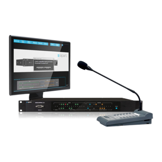
AUDIOCONTROL12.8 RS232 serial control Online user manual... - Page 2 AudioControl 12.8 RS232 serial control Connecting the AudioControl unit to the computer via RS232: All you need is a serial cable (straight, no null modem cable !!!) and a working serial port on your computer. Alternatively, an industry standard USB to RS232 converter will do the job. IMPORTANT: Consult the manual of your USB to serial converter and make sure the drivers for the converter or integrated serial port are successfully installed before starting the AudioControl graphical installer interface program. Check the Windows device manager on your computer and make sure there are no unknown or disabled communication devices in the list (usually these communication devices are listed under “Ports”). The program will automatically scan all available com ports on your computer and will automatically configure the serial port the AudioControl is connected to. No further user action is required for making the connection. No specific drivers are needed for the AudioControl unit, because all communication with the computer is done via RS232 commands. Please note: depending on your hardware configuration, not all com ports listed in the Windows device manager are RS232 ports ! Consult an IT professional in case of doubt or check the com port properties in device manager. Despite the fact that serial ports are becoming rare on modern computers, they are still commonly used in home/office automation and control systems. There are many benefits to using serial ports: the protocol is very reliable and does not depend on operating system driver policies or restrictions. For your reference, serial port parameters are as follows: baudrate 19200, 8 databits, 1 stopbit, no parity. The serial cable used for communicating with AudioControl is a straight through, one to one serial cable (NO null modem cable). If you experience any communication problems, first check the RS232 A in/out leds on the front panel. These should flash (briefly) when commands are sent/ received successfully. When the leds remain unlit at all times, no connection has been made and you will be unable to configure the unit. !!! Note: connection from the PC to the AudioControl unit is made with a standard RS232 straight cable, connected to the front RS232/A port on the AudioControl unit !!!
- Page 3 Straight RS232 cable: PC to AudioControl port A: The rear mounted RS232/B and C connectors are meant for communication between the AudioControl unit and other peripherals. If you want to control Apart-audio RS232 compatible devices, you need a CROSSED serial cable. For other brands, a STRAIGHT or CROSSED serial cable is used, depending on the peripheral device. Crossed cable: AudioControl to Apart-audio peripherals: Keep your software and firmware up to date ! Check our website for the latest firmware and graphic installer interface program: www.apart-audio.com Before you try to install the latest interface program, please uninstall the previous version via the Windows control panel / programs. Uninstalling the program will not erase your expert password stored on your computer. In order to obtain an expert level password please contact your local distributor.
- Page 4 Instruction set AudioControl 12.8 The AudioControl 12.8 can be controlled using RS232 strings sent by other units, such as home automation systems for example. RS232/A front panel port settings are 19200 bits per second, 8 data bits, no parity, 1 stop bit and no flow control. RS232/A port settings are fixed. RS232/B and C rear panel ports can be configured via serial commands or the Graphic installer interface program. Standard ASCII strings are used to control the AudioControl 12.8 so it is possible to use Terminal software (e.g. HyperTerminal, Hercules, ...) to test, configure and/or control it. Instructions are not case sensitive. Each string must be ended with a Carriage Return (<CR>, ASCII code 13 or ”\n”). Alternatively, if you like to look up the syntax of the possible strings and AudioControl 12.8 answers sent via RS232, open the program’s log window while operating the unit via the program. The string is structured in the following order: Command Attribute Parameter1 Value<CR> Strings require a space between each parameter; the last character in the string needs to be a carriage return <CR>. Line feed <LF> characters are ignored so they may be used. An instruction consists of a command, an attribute and possible one or more parameters. E.g. the instruction to switch the music volume from zone 1 at maximum level will look like this: SET MSCLVL ZONE1 12<CR> where SET is the command, MSCLVL the attribute, ZONE1 the first parameter and 12 the second parameter which is the maximum value in this case. Commands: This is a list of known commands with a brief description SET set the value of a variable GET get the value of a variable DEC decrease the value of a variable INC increase the value of a variable RECORD start recording a macro PLAY play back/execute a recorded macro or command string STOP stop recording ERASE erase a command string or a macro...
- Page 5 Attributes: This is the list of known attributes with a brief description, most of them are self explanatory. MIXLVL mix level MSCLVL music level MIXMAS mix master VOLUME volume PAGLVL paging level MSGLVL message level CHMLVL chime level PAGMAS paging master SELECT select DELAY delay TRIM trim INGAIN input gain EQGAIN equalizer gain MINLEVEL minimum level MAXLEVEL maximum level PMBASSIGN paging mic button assign STRING string WALLPANEL wall panel PAGINGMIC paging microphone SERIAL serial SPDIFOUT...
- Page 6 FREQ frequency MONITOR monitor TIME time DATE date MSSG message MACRO macro ENABLE enable TIMEDPR timed preset GLOBAL global VIRTUAL virtual SWVRSN software version HWVRSN hardware version INFO information NAME name RESTORE restore END end USERID user identification IMPORT import WPMODE wall panel mode PASSWORD password GPIO general purpose input/output UNDEF1...
- Page 7 An instruction is made of a command, an attribute and one or more parameters (values), depending on the type of instruction. The best and easiest way to determine the syntax of an instruction and to determine the possible parameter values is to use the dedicated AudioControl 12.8 installer interface program, log in with your expert code, and operate the software while connected to an AudioControl unit. In order to obtain an expert level password please contact your local distributor. After obtaining your personal expert level password, install the software program and connect the computer to the AudioControl unit. Open the program, enter your expert level password and synchronize the settings with your computer. Now click on the “monitor” tab.
- Page 8 The following screen will pop up, now click on the RS232 log tab: The log screen will open up:...
- Page 9 Now click the “Clear log “ button. The log screen will be cleared. In the left pane you will see the outgoing instructions, sent by the computer to the AudioControl when you change a setting. In the right pane you see the answer sent by the AudioControl unit. With the help of a few practical examples, we will show you what the RS232 commands look like. Please note that the AudioControl unit will reply to any valid command set.
- Page 10 Example 1: By means of the examples on the next pages we will explain the easiest way to determine how an instruction is written. Leave the RS232 log screen open in the background. Now return to the installer interface program and change a setting, for example, lower the Zone 1 master level by 1 step. The RS232 log screen now looks like this:...
- Page 11 The command for lowering the zone 1 master by 1 step looks like this: DEC VOLUME ZONE 1 (followed by a <CR> command) The unit replies: VOLUME ZONE 1 -1 U E The volume of zone 1 has been lowered by 1 step. The “U” means that the zone 1 master is unmuted (not muted). The “E” means that the mute command is enabled. This means that you can send a mute command. NOTE: you can increment or decrement (INC or DEC) the volume in steps from 1 to 10. For example, you want to decrease the master fader level of zone 1 by 10 steps at once. The command looks like this: DEC VOLUME ZONE 1 10 Where the “10” can be a value from 2 to 10. If no value is specified, the unit will change by 1 step.
- Page 12 Example 2: We want to mute the zone 1 master: Click the mute button, it will become red to show that zone 1 is muted. The log screens looks like this: The program has sent this command: SET VOLUME ZONE 1 MUTE The unit will reply: VOLUME ZONE 1 -1 M E (the volume of zone 1, which was set at -1, is now muted). The “M” means muted. The “E” means mute enabled.
- Page 13 Example 3: In the installer interface, we now will disable the mute button for the zone 1 master fader: right click the zone 1 master fader and select “disable mute”. The mute button will become grey, meaning that you can not mute the zone 1 master.
- Page 14 The log screen looks like this: The incoming text field shows this: VOLUME ZONE 1 -1 U D The “D” at the end means that the mute button has been disabled.
- Page 15 Example 4: Determining the parameter upper and lower limits (values): Now it is easy to determine the parameter limits by using the installer interface program with the RS232 log screen open. We want to determine the limits of the zone 1 master fader. Slide the zone 1 master fader all the way up.
- Page 16 The log screen looks like this: The upper volume parameter limit is 12.
- Page 17 Repeat this for the lowest possible level. Slide the zone 1 master fader all the way down. The log screen now looks like this: The lowest possible value (parameter) for the zone 1 master fader is OFF, which corresponds to a value of -81. This value is visible in the numeric field above the master fader.
- Page 18 Example 5: Now we will show how to select a certain channel (input source) in a certain output zone. Together with the zone master level, these commands are the most common and will be used often in custom control systems, such as home automation systems. We want to select channel 2 in zone 1 as the music source: In the installer interface program, select channel 2 as the music source.
- Page 19 The log screen looks like this: The command for selecting channel 2 as the music source for zone 1: SET SELECT ZONE 1 2 !!! NOTE !!! When selecting a music source, only the selected music source will be audible in the zone, regardless of the position of the music source (channel) fader from the non selected channels! The sources that have been configured as microphone mix sources will be mixed to the zone output using the mic mix fader as you can see in the signal flow diagram.
- Page 20 You can repeat these steps for any other command. It is easy to select and copy the text string from the RS232 log screen, and copy/paste it into another program. RS232 error messages: When the command is unknown, the unit will reply: Unknown Command! • When a value is out of range or invalid, the unit will reply: Value Invalid! • When the attribute is invalid, the unit will reply: Instruction Invalid! • When the attribute is unknown, the unit will reply: Unknown Attribute! •...
Need help?
Do you have a question about the AUDIOCONTROL12.8 and is the answer not in the manual?
Questions and answers