
Related Manuals for MSNswitch UIS-322

Summary of Contents for MSNswitch UIS-322
- Page 1 Remote Power Management Solution for Crashed Network Devices USER MANUAL Version: 2203 (MNT.NBU.7322 or higher)
-
Page 2: Table Of Contents
Table of Contents Chapter 1: Introduction..................1.1. Introduction..............................3 1.2. Hardware Specification ........................4 1.3. Network Diagram ............................5 1.4. LED Indicators Explained ........................6 Chapter 2: Hardware Setup ..................Chapter 3: Software & Web Setup (For Advanced User) ......... 3.1. Introduction..............................8 3.2. How to Locate & Access IP Switch in LAN ..................8 3.2.1 Locate IP Switch in LAN using Utility program................ 9 3.2.2 Locate IP Switch in LAN using fixed IP..................9 3.3. How to Access IP Switch from WAN – using DDNS ..............11 3.4. How to Access IP Switch from WAN - using Google Talk/ Hangouts ......11 3.4.1. How to Setup Google Talk/ Hangouts for the IP Switch ............12 3.5. How to Access IP Switch from WAN – Using Skype..............14 3.6. How to Upgrade/ Re-Flash Firmware ...................18 Chapter 4: IP Switch Web User Interface .............. 4.1. Information ............................... 20 4.2 Configuration ............................21 4.3 Log Information ............................ -
Page 3: Chapter 1: Introduction
Chapter 1: Introduction 1.1. Introduction IP Switch is designed to automatically power-cycle either one or both of its outlets when either; a) Internet connectivity is lost (resets Router/Modem to restart it), or b) the network device being monitored is no longer responding in LAN. It can also be used to: a) remotely control outlets via instant messaging tool like Google Talk/ Hangouts, or a Web User Interface. -
Page 4: Hardware Specification
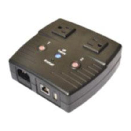
SNTP, DHCP. Operating Temperature: 0°C ~ 60°C; Operating Humidity: 10% ~ 90% For indoor use only. 1.2. Hardware Specification Model No: UIS-322 Socket type 2x of either; a) Universal socket (Type X) b) USA (Type B, NEMA 5-15R) AUST / China (Type I, AS / NZS3112, CCC) -
Page 5: Network Diagram
1.3. Network Diagram The following Network diagrams applies to all IP Switch models. Fig.1 IP Switch setup to perform auto reset of router and modem Fig.2 IP Switch setup to keep Internet device alive. -
Page 6: Led Indicators Explained
Fig.3 IP Switch setup for remote control via Google Talk/ Hangouts or thru Web User Interface. 1.4. LED Indicators Explained LED Status for Internet & Outlets LED status Condition description Internet connection available and UIS (Uninterruptable Internet Solid Green Internet System) mode has been activated. There is internet connection. -
Page 7: Chapter 2: Hardware Setup
Fig.5 LAN LED Indicators Fig.6 Description Chapter 2: Hardware Setup IP Switch hardware installation procedure: Step 1: Connect the power cord to device and wall outlet. The two orange LED will light up, indicating that the individual Outlet is ON. Press the Orange LED for 2 seconds to turn the Outlet On / Off. -
Page 8: Chapter 3: Software & Web Setup (For Advanced User)
Step 3: Connect LAN cable from your router. Step 4: Make sure the Internet LED light is blinking show that internet connection is ready. Press and hold the “UIS On/Off” button (about 2 seconds) to activate internet protection, which will allow the switch to auto reset upon loss of connection to the Target sites (i.e web site addresses or local IP addresses). -
Page 9: Locate Ip Switch In Lan Using Utility Program
3.2.1 Locate IP Switch in LAN using Utility program. Step 1: Download Utility program from http://3gstore.com/ipswitchupdates install. Once installed Utility will locate and list the IP Switch units. NOTE: Utility can only discover the IP Switch units that are located within the same LAN or network. - Page 10 Step 1: Connect the LAN cable from IP Switch to your PC’s Ethernet port Step 2: Assign a fixed IP within the same subnet to your PC. Example: IP address - 192.168.0.20; Subnet Mask 255.255.255.0; Gateway: 192.168.0.1 Step 3: On your PC, launch a web browser and enter the IP: 192.168.0.100 - Login username/ password: admin/ admin.
-
Page 11: How To Access Ip Switch From Wan - Using Ddns
3.3. How to Access IP Switch from WAN – using DDNS The IP Switch Web User Interface (Web UI) can be accessed remotely from Wide Area Network (WAN). To do so, you must have a public dynamic IP address from your ISP (Internet Service Provider) - if you’re unsure about this, please contact your ISP. -
Page 12: How To Setup Google Talk/ Hangouts For The Ip Switch
3.4.1. How to Setup Google Talk/ Hangouts for the IP Switch Step 1: From the Utility application, select ‘Launch Web User Interface’ - when prompted, log in with the default user name & password: User Name: admin Password: admin NOTE: If Utility cannot locate your Switch, please refer... - Page 13 Step 4: Once connected, you’ll want to log into your control Gmail account. The users listed in your Contact List will receive a notification to add the IP Switch as a ‘contact’. Once added, you can control the IP Switch by chatting with it. NOTE 1: If you do not receive an ‘invite’...
-
Page 14: How To Access Ip Switch From Wan - Using Skype
SET ON / OFF / RESET command will return a “Done!” once IP Switch has completed the action. GET IP command will return the WAN IP and the unit’s LAN IP address. *If port forwarding is set, but not the domain name, user can still use WAN IP to access the IP Switch Web User Interface from internet. - Page 15 Step 3: Initiate Skype: 1. Under Configuration Settings Select Skype 2. In the Skype Function Section Click on Enable 3. Then Click on Auto Rebooter (a separate tab will open see Step 4) 3. Click Apply Step 4: Auto Rebooter 1.
- Page 16 Step 5: Open The Skype App 1. Under the Contacts Section select Auto Rebooter 2. Type Help 3. Click Get My ID 4. Copy and Paste the ID...
- Page 17 5. Toggle back to the Admin Screen 6. Enter the Name for your Switch (any name you want to represent) 7. Paste the ID in the ID field 8. Click Add Step 6: Skype Control 1. Switch back to the Skype App 2.
-
Page 18: How To Upgrade/ Re-Flash Firmware
Result Other Commands: Outlet 1 or 2 Turn ON Turn OFF Reset Back Turn ON Turn OFF Back Note* If you have multiple outlets, just use the same ID (from Get My ID) 3.6. How to Upgrade/ Re-Flash Firmware When issues occur with your IP switch, it is best to upgrade firmware (if available) or re-flash the current version of firmware. - Page 19 Upgrade Using Utility Step 1: Launch the ‘Utility’ Windows Application and let it detect IP switch. Step 2: Click on the ‘Firmware Upgrade’ button. NOTE: If Utility cannot locate your Switch please refer back to section 3.2.1 Step 3: In the dialog box that opens, select the ‘…’...
-
Page 20: Chapter 4: Ip Switch Web User Interface
folder. Select the .bin file named and click Open Step 5: You'll now see the file appear next to 'Location’ -> Click Apply to begin the upgrade NOTE: The firmware process takes about 2-5 minutes. Chapter 4: IP Switch Web User Interface 4.1. -
Page 21: Configuration
Fig.7 Current Status page Connection Status Assign: This shows the outlets that are assigned to the target sites Site Label: A name for the target site Target Site: This is the default target site as listed under Configuration page IP Address: The IP address of the Target Site Response Time: based on UDP / TCP protocol sets in Configuration page Timeout: Number of timeouts as a percentage of total tries since reset. - Page 22 4.2.1 Configuration 4.2.2 Schedule 4.2.3 Network 4.2.4 E-mail 4.2.5 Account 4.2.6 Google Talk/ Hangouts 4.2.7 System Time 4.2.8 Language 4.2.9 SMS 4.2.1 Configuration Use this section to configure how IP Switch checks websites. Advance users can use this to customize IP Switch to check network devices. Website / IP Address Assign: Assign either one or both outlets to the website / IP address.
- Page 23 a group of websites will auto reset, when all sites within that group timeout. NOTE: Assignment cannot be for a combination of both and single outlets. Site Label: Give the IP address a short and easy to remember nickname. Max 16 characters.
- Page 24 Timeout for Each Website / IP Address Assigned websites must respond within this time else, it timeout. Set a larger value to allow for occasional internet lags. Default is 5 seconds. NOTE: A larger timeout will allow for instances of delay or lag from target sites.
- Page 25 New Schedule Event Item Select to schedule an event for either Outlet 1 or Outlet 2, Both, or UIS Reset. Action Select action to apply to above Outlets. To turn ON, OFF or RESET. Date (yyyy/mm/dd) Select the event frequency for the above outlet; a.
- Page 26 IP Address Hostname By default the hostname (LAN Domain Name) is set to Outlet. This should allow the unit to be located on your router's client list when determining the LAN IP address. NOTE: If you have multiple IP Switch units, you should assign different hostnames to each unit.
- Page 27 Primary DNS Server IP The default IP Switch Primary DNS Server IP is 208.67.222.222. User can set their preferred DNS server / one that is assigned by ISP. Secondary DNS Server IP Use this to set IP Switch Secondary DNS Server IP address. IP Switch will use the Secondary DNS Server IP address if the Primary DNS Server IP address is not working.
- Page 28 Dynamic DNS (“DDNS”) is a third party service – some providers offer free service, others require a fee. It allows the user to alias a dynamic WAN IP address to a WAN hostname. So no matter how many times your ISP changes the IP address, you will be able to locate your unit over WAN using your DDNS hostname.
- Page 29 E-mail Settings E-mail Notification When ‘Enabled’ and settings are applied, user can receive notifications form the Switch. 2 additional sections will appear that also must be configured – ‘Test E-mail’ and ‘E-mail Address Book’ E-mail Server Only SMTP servers are supported. IMAP &...
- Page 30 Send a test E-mail Enter a valid e-mail address to send the test email to. Example of email received: iii. E-mail Address Book E-mail Address Book List the users who shall receive an e-mail notification, as they appear in the Event Log section.
- Page 31 Administrator account is set up by default. Viewer account can be configured if users want to allow others to view the settings without being able to make any changes. Login The administrator can set a name consisting up to 32 case sensitive characters. By default the Administrator Login and Password are both admin / admin.
- Page 32 Enter the Login ID that you have created from the Gmail website for the IP Switch. Password Enter the corresponding password with the above account. Show a Personal Message for Account Enter a message here. This message will be visible to anyone that is in the IP Switch’s Hangouts contact list.
- Page 33 Time Between Automatic Updates The user can set an interval for time synchronization. Select from either; none, 1, 3, 12 hours or 1, 10 & 30 days. Default is 1 Hour. Time Server Choose the nearest Time Server to your location. The user can choose from the list of a maximum of 30 Time Servers.
-
Page 34: Log Information
*This feature is NOT supported at this time. 4.3 Log Information 4.3.1 Event Log This section will log events that occurred on the IP Switch and categorize them. Fig.10 Event Log Event Log Type Select which type of log to show: a. - Page 35 System Information This section shows general hardware information such as the Hardware and Firmware Version, the serial number, Uptime, System Time and when the system last reset. Network Status This section shows all information relating to the Network environment. Hostname This is the default hostname.
- Page 36 Restore Use this function to restore a *.cfg configuration that has been saved earlier. Click Browse… and locate the file you saved. Click Restore. Reset to factory default This function will reset all settings to its default configuration. Upgrade Firmware Firmware Version Displays the current firmware version running on the Switch.
-
Page 37: Chapter 5: Troubleshooting Tips
Chapter 5: Troubleshooting Tips 1. Assign a static IP (manual) address to the Power Switch rather than using DHCP. a. Like with most LAN connected, remote devices this is a more stable/reliable way of connecting the Switch to your network b. - Page 38 5. Check the Fuse: If your IP Switch is not powering ON, it’s possible the fuse may be bad. Follow the steps below to change out the fuse with the back up a. Remove the Power Cord and Ethernet Cable from your IP Switch before proceeding.
- Page 39 c. With the Fuse Door removed, swap the main fuse with the backup. (Left - Backup, Right - Main) d. Return the Fuse Door to the IP Switch, making sure it sits flush with the surrounding surface. Reconnect the Power Cord and Ethernet Cable.
-
Page 40: Appendix A: Router Configuration
Appendix A: Router Configuration The following section describes the initial configuration of the router and port forwarding for your router. If your router is not listed here, please refer to the manufacturer’s website for assistance with configuring your router to work with IP Switch. - Page 41 DI-704/704P 1. Log into your router using your router IP. 2. On the main page, click on Advanced at the top of the page. 3. On the Virtual Server page, enter the following information: For ID#1: Service Port: Service IP: Type in the IP Switch IP address, for example: 192.168.0.5 Enabled/Disabled: Enabled...
-
Page 42: Appendix B: Ip Address, Subnet And Gateway
MN-100 – Wired Base Station MN-500 – Wireless Base Station 1. Log into your router using your router IP. 2. Open the Bass Station Management Tool, and then click Security. 3. On the Security menu, click Port Forwarding, and then click Set up persistent port forwarding. - Page 43 transmitted. IP addresses appear in dotted decimal (rather than in binary) notation. Dotted decimal notation divides the 32-bit value into four 8-bit groups, or octets, and separates each octet with a period. For example, 199.217.132.1 is an IP address in dotted decimal notation.
-
Page 44: Appendix C: Glossary
255.0.0.0 IP packets are only transmitted to devices that are IP that’s first octet matches the sender’s IP address’s first octet. 255.255.0.0 IP packets are only transmitted to devices that are IP that’s first two octets match the sender’s IP address’s first two octets. 255.255.255.0 IP packets are only transmitted to devices that are IP that’s first three octets match the sender’s IP address’s first three octets. -
Page 45: Google Talk 2 Step Authentication
Google Talk 2 Step Authentication Due to compatibility, we suggest ensuring your IP Switch is running firmware version 2.40.MNS.NBU.5106, or newer. This firmware, as well as the Utility software needed to upload it, can be downloaded at http://3gstore.com/ipswitchupdates or by logging into your 3Gstore account at http://3gstore.com/support, which is where you can also find our “IP Switch Firmware Upgrade Steps”... - Page 46 8. Scroll down to the “Signing in to Google” section 9. Confirm that 2-step Verification is Off** 10. Click “Connected apps & sites” on the left 11. Scroll down to the “Allow less secure apps” section and turn it ON 12.
- Page 47 Applying settings to your IP Switch *NOTE: If configuring for the first time, steps must be done at the same location and on the same local network as the IP Switch. 1. Use the Utility software to locate your IP switch on the network, then click “Launch Web User Interface”...
- Page 48 3. Under the ‘Configuration Settings’ section on the left click ‘Hangouts’ 4. Under ‘Status’ at the top left of this page, select ‘Online’ 5. For the ‘Login ID’ enter the Gmail Account you just created (i.e. gtalk3g@gmail.com ). This again will act as the IP Switch account. 6.
- Page 49 *The Commands you will be able to send via Chat are: Note: 0/1/2 = Variables are for specified power outlets 1, 2, or 0 for both ports SET ON 0/1/2 ‐ This turns On the Power to the specified port(s) SET OFF 0/1/2 ‐...
- Page 50 the “Allow Less Secure Apps” option is turned ON. These are both found under the “My Account” section of Gmail. 2. Wait at least 5 minutes while the Switch tries to Sign In. It will go back and forth between signing in and showing the connection error - sometimes we’ve seen this process take longer than a minute.
Need help?
Do you have a question about the UIS-322 and is the answer not in the manual?
Questions and answers