Electronics International UBG-16 Operating Instructions Manual
Ultimate bar graph engine analyzer
Hide thumbs
Also See for UBG-16:
- Operating instructions manual (31 pages) ,
- Installation instructions manual (35 pages)
Table of Contents
Advertisement
Quick Links
Ultimate Bar Graph Engine Analyzer
(UBG-16)
Operating Instructions
OI 0505991
5/5/99
Rev. B: 3/10/00
You must read this manual before installing or operating the instrument. This
manual contains warranty and other information that may affect your decision
to install this product and/or the safety of your aircraft.
EI
Electronics International Inc.
®
63296 Powell Butte Hwy • Bend, OR 9770 • (541) 318-6060 • Buy-EI.com
Advertisement
Table of Contents

Subscribe to Our Youtube Channel
Related Manuals for Electronics International UBG-16


Summary of Contents for Electronics International UBG-16
-
Page 1: Operating Instructions
You must read this manual before installing or operating the instrument. This manual contains warranty and other information that may affect your decision to install this product and/or the safety of your aircraft. Electronics International Inc. ® 63296 Powell Butte Hwy • Bend, OR 9770 • (541) 318-6060 • Buy-EI.com... -
Page 2: Important Notice
Important Notice ***** MUST READ ***** If you think it is not important to read this manual, you're wrong! This manual contains important operating information that may affect the safety of your aircraft. Rev. C 9/24/97... - Page 3 Contents Warranty ------------------------------------------------------------------------------------------...
- Page 4 Contents Continued: UBG-16...
-
Page 5: Warranty / Agreement
Electronics International Inc. 4. Electronics International Inc. is not liable for expenses incurred by the customer or installer due to factory updates, modifications, improvements, upgrades, changes, or any other alterations to the product that may affect the form, fit, function or operation of the product. -
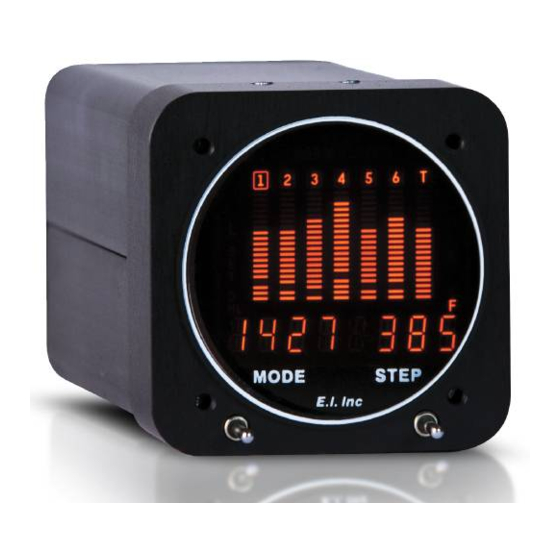
Page 6: Mode Selector Switch
Introduction Mode Selector Switch: Figure 1 Figure 2 Figure 3 Mode Switch Normal Operating Mode:... -
Page 7: Step Switch
Step Switch: 1. Displaying the EGTs and CHTs: Step Switch 2. Displaying a Temperature on the 7th Column of Bars:... - Page 8 3. Displaying Other Temperatures and/or Functions Digitally: 4. Displaying the Shock Cooling Rate: 5. Displaying the Peak EGT and Cylinder:...
- Page 9 6. Displaying the EGT Difference: Scanning Through the Channels Automatically: Normalized Operating Mode:...
-
Page 10: Lean Operating Mode
Lean Operating Mode:... - Page 11 1. False Peaks: 2. Leaning on the Rich Side of Peak:...
- Page 12 3. Alternate Method for Leaning on the Rich Side of Peak: 4. Leaning on the Lean Side of Peak: 5. Method for Checking the Mixture Setting when Operating on the Lean Side of Peak:...
- Page 13 Alarms: 1. High and Low Alarm Annunciators: 2. EGT Differential Alarm Annunciator: 3. Shock Cooling Alarm Annunciator: 4. Finding the Channel on which a Programmed Limit has been Violated:...
-
Page 14: Programming The 34 Limits
5. Canceling all Active Alarms for 10 Minutes: 6. Activating all Canceled Alarms: Programming the 34 Limits: Programming the High and Low EGT and CHT Limits: 1. Selecting the High EGT Limits:... - Page 15 2. Selecting the Lower EGT Limits: 3. Selecting the High CHT Limits: 4. Selecting the Lower CHT Limits:...
-
Page 17: Programming The Range Of The Egt Columns Of Bars
Programming the Range of the EGT Columns of Bars: 1. Selecting the Upper EGT Bar Trip Point: 2. Selecting the Lower EGT Bar Trip Point:... - Page 18 Programming the High and Low Limits and Range of the 7th Col- umn of Bars:...
- Page 19 Programming the High and Low Limits for Other Temperatures or Functions:...
- Page 20 " " " " " " " " " "...
- Page 21 Programming the Shock Cooling Limit and Cylinder: Programming the EGT Differential Limit:...
-
Page 22: Power-Up Programming
Power-up Programming:... - Page 23 1. Enter the Power-up Programming Mode: 2. Configuring EGT and CHT Channels: 3. Configuring the 7th Column of Bars:...
-
Page 24: Operating The Ubg In Your Aircraft
4. Configuring the Remaining Left and Right Channels: 5. Exiting the Programming Mode: Operating the UBG in Your Aircraft: 1. Taxi: 2. Run Up:... - Page 25 3. Takeoff: 4. Climb: 5. Cruise:...
- Page 26 6. Descent:...
-
Page 27: Work Sheet For Setting Limits
Work Sheet for Setting Limits 1. During High Power Climb to 5,000 ft. +: 2. During Cruise, Normal Power, Around 2,000 ft. , Full Rich: 3. During Cruise, Normal Power, Around 2,000 ft. , Leaned to Peak: 3. Set Other Limits:... - Page 28 "UBG-16" Configuration Form:...
-
Page 29: Fuel/Air Profile
Fuel/Air Profile... -
Page 31: Specifications And Operating Features
SPECIFICATIONS and OPERATING FEATURES...
Need help?
Do you have a question about the UBG-16 and is the answer not in the manual?
Questions and answers