Table of Contents
Advertisement
Quick Links
User manual
Compact controller
DEGA UPA III
Reproduction of this manual, or any part thereof, in any form, without the prior permission of
DEGA.CZ s.r.o. is prohibited.
DEGA CZ s.r.o. reserves the right to alter the specifications of the hardware and software
described in this manual at any time and without prior notice.
DEGA CZ s.r.o. bears no liable for any damage resulting from use of this device.
Advertisement
Table of Contents

Subscribe to Our Youtube Channel
Related Manuals for DEGA UPA III

Summary of Contents for DEGA UPA III
- Page 1 Reproduction of this manual, or any part thereof, in any form, without the prior permission of DEGA.CZ s.r.o. is prohibited. DEGA CZ s.r.o. reserves the right to alter the specifications of the hardware and software described in this manual at any time and without prior notice.
-
Page 2: Table Of Contents
Content For your safety ....................................2 Technical data ....................................3 Operational conditions ..................................3 Product description ................................... 3 Outer case ....................................4 Terminal block ..................................4 Assembling and connecting the wiring ............................. 5 Assembly of the controller ..............................5 Connecting a transmitter via current loop ........................... 5 Connecting a transmitter via RS485............................ -
Page 3: Technical Data
It is used to supply up to 32 transmitters via RS485 and up to 8 transmitters via current loop. It evaluates the gas leak of the transmitters in 4 levels. It is also possible to connect one flooding sensor DEGA ZC II and one... -
Page 4: Outer Case
is equipped with 10 pieces of freely configurable relays, 2 outputs for visual and acoustic alarms, an output for impulsive closing of emergency valves, a USB port and a RS485 for connecting to the host system (PLC, PC with visualization) Outer case Bottom Indents for... -
Page 5: Assembling And Connecting The Wiring
Assembling and connecting the wiring Before assembling, read the valid instalation standarts EN 60079-29-2 (Selection, instalation, use and maintenance of detectors for combustible gases and oxygen) and EN 45544-4 (Guildelines for the selection, installation, use and maintenance of detectors of toxic substances). In explosive environments the electrical installation must be performed according to ČSN EN 60079-14 (Electrical instalation in hazardours areas). -
Page 6: Terminal Resistor
Terminal resistor According to the RS485 specifications, the last device on the bus must be ending with a terminating resistor 120R. Plug a jumper on the JP2 connector of the last device on the bus to include the 120R terminating resistor. -
Page 7: Output Relay
Example: There are 4 transmitters connected to the controller with a consuption of 60 mA each. The controller has a consuption of 300mA. The remaining 7,46 A (I=8000-300-4x60) are used to supply the visual and acoustic alarms. Information on the constuption of each transmitters and components of the visual and acoustic alarms is given in the respective manuals. -
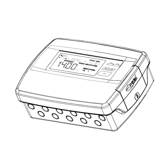
Page 8: Lcd Display
2. LCD display Date Secondary display Warning: calibration Time required RS485 address of the „Channel“ of the Interrupted RS485 Transmitter calibration current transmitter current transmitter bus indication via RS485 Marker (selecting a Malfunction of the Exceeding the Indication of an alarm transmitter in the controller or a critical temperature... -
Page 9: Malfunction
5. Malfunction If a malfunction should occur, the LCD displays the measured values, an error code and also a key symbol . The meaning of individual error codes can be found in the attachments. 6. Monitoring the calibraton periods After 12 months since the last calibration (Max. calibration interval) an inscription starts flashing on the LCD display. -
Page 10: History Menu Hist
Displays the date of the next transmitter calibration LCAL Displays the date of the calibration TEMP Displays the temperature of the DEGA Tc II sensor ADDR Displays the controller address on the RS485 HOST bus EXIT Returns to a higher menu level For entries „LCAL“... -
Page 11: Controller Testing Menu Test
The entries TMP1 and TMP2 change the temperature value of the external sensor at which an alarm occurs. Pressing LEFT decreases the temperature and pressing RIGHT increases the temperature. Press ENTER to confirm the change. Attention, the temperature alarm value changes immediately after pressing LEFT or RIGHT. If the immediate temperature value exceeds the alarm value, it will change the output state. -
Page 12: Maintenance
For the „functional control“ do not use means for testing fire alarm detectors! Perform calibration only at certified service centers with a valid certificate of competence or the manufacturer. For the Czech Republic only DEGA CZ s.r.o. 2. Replacement of the battery The battery lifetime in the controller is approximately 5 years. -
Page 13: Attachments
Attachments 1. Table of error codes Occurs on digital Occurs on analog Displayed on the channels channels Cause Solution secondary segments (1 to 32) (41 to 48) Check the transmitter Interrupted current loop connection, otherwise „SENSOR E“ or faulty transmitter contact the manufacturer Sensor is not present... -
Page 14: General Warranty Terms And Conditions
DEGA products that have been used in association with other than original DEGA products, including consumables and accessories ...
Need help?
Do you have a question about the UPA III and is the answer not in the manual?
Questions and answers