Table of Contents
Advertisement
Quick Links
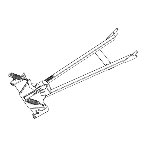
ATV STORM CHASER PLOW
PUSH TUBE KIT
P/N 33-0070
OWNER'S MANUAL
Application
MID-BODY ATV MOUNT NO. 15-XXXX, ALL MOUNT NO. 15-0050
ATTENTION DEALER: CUSTOMER MUST RECEIVE A COPY OF THIS MANUAL
AT THE TIME OF SALE.
Before you begin, please read these instructions and check to be sure all parts and tools are
accounted for. These instructions will help you to become familiar with operation of the plow push
frame. Instructions contain details required to install, service the contents of this kit, for adjustment
and maintenance.
© 2017 Kolpin Outdoors Inc.
REV 03
Advertisement
Table of Contents

Subscribe to Our Youtube Channel
Related Manuals for Kolpin 33-0070

Summary of Contents for Kolpin 33-0070
- Page 1 These instructions will help you to become familiar with operation of the plow push frame. Instructions contain details required to install, service the contents of this kit, for adjustment and maintenance. © 2017 Kolpin Outdoors Inc. REV 03...
- Page 2 INTRODUCTION Congratulations! You’ve just purchased one of the industry’s top plow system component. The Kolpin Plow Push Frame works great for all types of plowing. With proper care and maintenance, your plow push frame will last for many years! The blade pivot design allows the operator to select multiple angled left-or-right positions, and also incorporates a spring-loaded ’trip’...
-
Page 3: Safety Information
APPROXIMATE ASSEMBLY TIME: 15 minutes Note: The Kolpin Plow Push Frame kit comes mostly assembled from factory. Some assembly is required. RE-TORQUE ALL BOLTS AND NUTS AFTER THE FIRST 30 MINUTES OF USE. - Page 4 Small bushing, Ø11mm ID x Ø25 mm OD x 8mm LG Hex Bolt, Zinc Plated, M10-1.5 x 35mm Hex Bolt, Zinc Plated, M12-1.75 x 40mm Spring Loop Washer Plate Hex Bolt, Zinc Plated, M14-2.0 x 50mm Kolpin Decal Owner’s Manual (not shown) © 2017 Kolpin Outdoors Inc. REV 03...
- Page 5 Kit Contents (continued): © 2017 Kolpin Outdoors Inc. REV 03...
-
Page 6: Installation
Fasten with M10 washer, item #15, and M10 nut, item #11. Tighten to specification. (See 10MM FASTENER TORQUE: 34 ft-lbs. (46 N-m) illustration 1-2) Note the small bushing fits in between pivot bracket and push frame © 2017 Kolpin Outdoors Inc. REV 03... - Page 7 ILL. 2-2 tab brackets. Fasten eyebolts to frame tab with M8 hex nylon nuts, item #9, onto the eyebolts until 2-3 threads show thru the locking feature. (See illustration 2-2) © 2017 Kolpin Outdoors Inc. REV 03...
- Page 8 (See illustration 2-4) 5. Tighten the blade stopper plate fasteners to specification. BLADE STOPPER ADJUSTMENT 10MM FASTENER TORQUE: ILL. 2-4 34 ft-lbs. (46 N-m) © 2017 Kolpin Outdoors Inc. REV 03...
- Page 9 Hex Bolt, Zinc Plated, M12-1.75 x 40mm Spring Loop Washer Plate Hex Bolt, Zinc Plated, M14-2.0 x 50mm Hardware kit Pivot Lock Lever kit (PN 33-0070-HDW) (PN 33-0070-CP04-B) Pivot Lock Lever Bracket kit (PN 33-0070-CP03) © 2017 Kolpin Outdoors Inc. REV 03...
-
Page 10: Operation
OPERATION: WINCH CABLE PUSH FRAME LIFT POINT: The winch lift point for the Kolpin push frame is the round hook hole as shown below. (See illustration 3-1) ILL. 3-1 Primary hook lift point PIVOTING BLADE ANGLE SIDE TO SIDE: To adjust the angle of the plow blade so it pushes to the side, lift the plow up with the lift mechanism to clear the ground. Pull the pivot lock lever toward the blade and swivel the plow to desired angle. - Page 11 Turn adjustable plow stoppers to one of the four positions in order to make the plow more aggressive or less aggressive. Position 1 is the position with less material. (See illustrations 3-3 and 3-4) ILL. 3-3 Less aggressive More aggressive Less aggressive More aggressive ILL. 3-4 © 2017 Kolpin Outdoors Inc. REV 03...
- Page 12 (See illustration 3-6) ILL. 3-6 FASTENER TIGHTNESS: Be sure to frequently check that the (5) fasteners of the pivot frame assembly are always tight to ensure good system function. (See illustration 3-7) Fasteners ILL. 3-7 © 2017 Kolpin Outdoors Inc. REV 03...
- Page 13 One Year Limited Warranty For the period of one (1) year from the purchase date, Kolpin will replace for the original purchaser, free of charge, any part or parts found upon examination by Kolpin to be defective in material, workmanship, or both.
Need help?
Do you have a question about the 33-0070 and is the answer not in the manual?
Questions and answers
If I adjust the blade stoppers will I get a better scrape
Yes, adjusting the blade stoppers on the Kolpin part number 33-0070 can improve scraping performance. Turning the adjustable plow stoppers allows the plow to be set in one of four positions, making the scraping angle more or less aggressive, depending on the desired performance.
This answer is automatically generated