Advertisement
Quick Links
Energy Measuring Unit
Model
EMU4-BD1-MB
EMU4-HD1-MB
User's Manual (Digest)
・Before using this unit, please read both this manual and Details carefully and pay attention to safety to handle this unit correctly.
・Make sure that the end users read this manual and then keep the manual in a safe place for future reference.
ABOUT MANUALS
You can download User's manual (Details) of this
unit from the following site.
http://www.mitsubishielectric.com/fa/worldwide/index.html
1. Features
(1) This Energy Measuring unit can measure various types of electric quantity such as voltage, current, electric power and electric energy.
(2) The measurement data can also be transmitted to superior monitoring systems through MODBUS RTU communication.
(3) In addition to the provision for measuring the quantity of electricity, the unit has two external input ports supporting both pulse input and contact input by way of switching (EMU4-HD1-MB).
With pulse input set, you can measure the production volume or the utility other than electricity, such as water, gas and air.
With contact input set, you can monitor status or alarm and measure the operating time of facility or the operating power.
MODBUS is a registered trademark of SCHNEIDER ELECTRIC USA, INC in the United States.
2. Checking package contents
This following items for this device and included in package. Check that no items are missing.
(1) Energy Measuring unit x1
(2) User's Manual (Digest) x1
3. Safety Precautions
3.1 Precautions for Operating Environment and Conditions
This unit is premised on being used in pollution degree 2* environment. When used in higher pollution degree, protect this unit from pollution on another device side to be incorporated.
Over voltage category of measuring circuit in this unit is CAT III*, and that of auxiliary power circuit (MA, MB) is CAT III*.
Do not use this product in the places listed below. Failure to follow the instruction may cause malfunctions and a life decrease of product.
・Places the Ambient temperature exceeds the range -5 - +55°C.
・Altitude exceeds 2000m.
・Places in strong electromagnetic field or places large amounts of external noise exist.
・Places exposed to direct sunlight
・Places exposed to rain or water drop.
This unit is the open type device, which are designed to be housed within another device for prevention of electric shock. House this unit within the device such as the control panel before use.
For the precautions for the compliance of the system incorporating this unit with the EMC Directives, refer to the User's Manual (Details).
*: For the definition of the pollution degree and the over voltage category, refer to EN61010-1/2010.
3.2 Matters concerning the precaution before use
・Use the unit in the specified usage environment and conditions.
・The setting of this unit (phase system, primary voltage and primary current, sensor type) is necessary before use it. Please refer to User's Manual (Details) about each setting method.
3.3 Installation and Wiring Precautions
Danger
・Shut off the external power supply for the unit in all phases before installing or wiring. Failure to do so may cause an electric shock or damage of this unit.
・Any person who is involved in the installation and the wiring of this unit should be fully competent to do this work.
・Work under the electric outage condition when installing and wiring. Failure to do so may cause electric shock, a failure of the unit, a fire etc.
・When tapping or wiring, take care not to entering any foreign objects such as chips and wire pieces into this unit.
・Check the connection diagram when wiring. Wrong wiring may cause failure of the unit, a fire or electric shock.
transmission lines and input/output lines shall not be placed close to or bound together with the power lines and high-voltage lines.
・For protection against noise,
・Strip the wires with proper length. Overlong stripping length may cause short to next wire. Shorter stripping length may cause contact failure.
・Take care not to short to next terminal by a filament. (Do not plate the wires with solder.)
・Do not connect more than two wires to one terminal of a terminal block for preventing loose contact and wires dropout.
・Use appropriate size of electric wires. If inappropriate size of electric wire is used, it may cause a fire due to generated heat.
・Tighten the screw within the specified torque. Under tightening can cause drop of the screw, short circuit or malfunction. Over tightening can damage the screw and/or unit, resulting in
drop, short circuit or malfunction.
・After tightening the screws, be sure to check all the screws tightened. Loose screw may cause malfunction of the unit, a fire or electric shock.
・Be sure to attach the terminal cover to prevent electric shock.
・Use the crimp-type terminal appropriated for the size of electric wires. If inappropriate crimp-type terminal is used, a wire breakage or a contact failure may occur, which may cause a
device malfunction, a failure, a burnout or a fire.
・FG terminal must be grounded according to the D-type ground (ground resistance is not exceed 100Ω).
High-voltage protective element is mounted between MA and FG, MB and FG. When applied high voltage, for example during a commercial frequency withstand voltage test, protective
element works to short between MA and FG, MB and FG.
Caution
・Do not directly touch any conductive part of the unit. Doing so can cause electric shock, failure or malfunction of the unit.
・When using this product, make sure to use it in combination with the current sensor (EMU-CT***, EMU-CT***-A, EMU2-CT5, EMU2-CT5-4W). Please not to exceed the rating of this
product for input of the current sensor. For further details, please refer to the manual for the current sensor to maintain the functionality and the accuracy of this product.
• The dedicated current sensor (EMU-CT***, EMU-CT***-A) is used only for low voltage circuit. It cannot be used for a high voltage circuit. EMU2-CT5 and CT5-4W should be used with
the secondary side (5A) of transformer transfixed. If it is connected with a high-voltage circuit by mistake, it may cause a burnout of the device and a fire. It is critically dangerous. For the
allowable maximum voltage of current sensor, refer to User's manual (Details) 13 "Option devices" (1) Specifications.
・When using this product, make sure to use it in combination with current sensor (EMU-CT50/CT100/CT250/ CT400-A/CT600-A, EMU2-CT5 and EMU2-CT5-4W).Please not to exceed
the rating of this product for input of current sensor. For further details, please refer to current sensor manual to maintain the functionality and the accuracy of this product.
・The dedicated current sensor (EMU-CT50/CT100/CT250/ CT400-A/CT600-A) is used only for low voltage circuit. It cannot be used for a high voltage circuit. EMU2-CT5 and CT5-4W
should be used with the secondary side (5A) of transformer transfixed. If it is connected with a high-voltage circuit by mistake, it may cause a burnout of the device and a fire. It is
critically dangerous. For the allowable maximum voltage of current sensor, refer to User's manual (Details) 13 "Option devices" (1) Specifications.
・The dedicated current sensor has a polarity (directionality). Be careful about it when installing the unit.
・The wires to be connected to this unit shall be placed in a duct or fixed together by cramping. If the electric wires are not placed in the duct or cramped together, loosen wires or their
movement or careless stretch may cause a breakage of the unit or wire or a malfunction due to poor contact of electric wires.
・If the wires connected to this unit are strongly pulled off, it may cause a malfunction or a breakage to the unit or the wire.
・Do not exceed the specified voltage when doing an insulation resistance test and a commercial frequency withstand voltage test.
・To prevent persons with little knowledge about electric equipment from electric shock, panel must be taken either following measure.
Lock the panel so that only those who get an education about electric equipment and have sufficient knowledge can unlock, or shut off power supply automatically by opening the panel.
Cover the dangerous part of this unit.
3.4 Precautions for Use
・Use this unit within the ratings specified in this manual. If it is used outside the ratings, it may cause not only malfunction or failure but also fire burnout.
・Do not disassemble or modify this unit. It may cause failure, malfunction, injury or fire.
Caution
・Do not touch the live part such as connection terminal. It may cause electric shock, electric burn injury or burnout of the device. If any exposed conductor is found, stop the operation
immediately, and take an appropriate action such as isolation protection.
3.5 Maintenance Precautions
・Use a soft dry cloth to clean off dirt of the unit surface. Do not let a chemical cloth remain on the surface for an extended period of time nor wipe the surface with thinner or benzene.
・Check for the following items to use this unit properly for long time.
(1) Daily maintenance
(a) No damage on this unit
(b) No abnormality with LCD
(2) Periodical maintenance (Once every 6 months to 1 year)
・No looseness with installation and wire connection
Do periodical maintenance under the electric outage condition. Failure to do so may cause electric shock, failure of the unit or a fire. Tighten the terminal regularly to prevent a fire. In
Caution
case a display unit is attached to a sensor unit, get off the display unit during maintaining or tightening terminals.
3.6 Storage Precautions
To store this unit, turn off the power and remove wires, and put it in a plastic bag.
For long-time storage, avoid the following places. Failure to follow the instruction may cause a failure and reduced life of the unit.
・Places the Ambient temperature exceeds the range -10 - +60°C.
・Places the Relative humidity exceeds the range 30-85% or places with dewfall.
・Dust, corrosive gas, saline and oil smoke exist.
・Places the average daily temperature exceeds 35°C.
3.7 Disposal Precautions
When disposing of this unit, treat it as industrial waste.
3.8 About packaging materials and this manual
For reduction of environment load, packaging materials are produced with cardboard, and this manual is printed on recycled paper.
If you are considering using this unit for special purpose such as nuclear power plants,
aerospace, medical care or passenger vehicles please refer to our sales
representative.
・Places the average daily temperature exceeds +35°C.
・Dust, corrosive gas, saline and oil smoke exist.
・Vibration and impact exceed the specifications.
・Places metal fragments or conductive substance are flying.
・Places the Relative humidity exceeds the range 30-85% or places with dewfall.
(c) No abnormal noise, smell or heat
・Vibration and impact exceed the specifications.
・Places exposed to rain, water drop or direct sunlight.
・Places metal fragments or conductive substance are flying.
4. Name and function of each part
4.1 Name of each part
(1) EMU4-BD1-MB
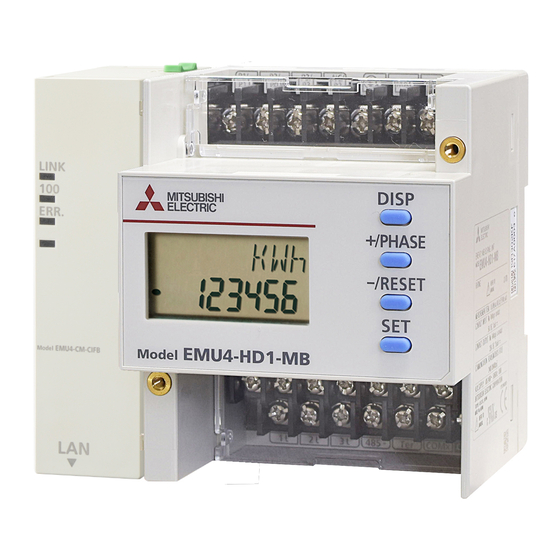
(2) EMU4-HD1-MB
Frame GND terminal
Voltage input terminals
Voltage input terminals
Power supply terminals
LCD
display
Operation
button
Current input terminals
Current input terminals
Communication terminals
(MODBUS RTU)
Communication terminals (MODBUS RTU)
4.2 Functions of operation buttons
Control buttons have many functions as below.
M ean ing of sym bo l: ○ (P ress), □ (P ress m ore than 1 sec), ◎ (P ress m o re th an 2 sec), ? (P ress b oth at the sa m e tim e)
Operation
N a m e of B u tton
DISP button
Mode
S E T
-/R E S E T
+ /P H A S E
D IS P
○
C h ang e m ea sured item s
+/PHASE button
○
C h ang e ph ase
C h ang e ha rm o nic order (a t ha rm o nic disp lay)
○
-/RESET button
C lear ala rm (at a larm keeping )
◎
◎
Tra nsition to con firm ation m ode
O p era tin g
Tra nsition to setting m ode
SET button
M o de
◎
◎
C on ta ct
C lear con ta ct latch
◎
disp lay
In tegra ted
◎
◎
Tra nsition to preset display
va lue
◎
◎
Tra nsition to reset d ispla y o f all da ta
disp lay
○
E nter setting m en u
M en u
M ovin g up or do w n of m enu n um b er
○
○
disp lay
(M ove a t fa st speed w hen pressin g m o re th an 1sec)
(□ )
(□ )
C h ang e of settin g item s (forw a rd)
○
Tra nsition to setting m en u num ber (a t final setting item )
S ettin g
M ovin g up or do w n of settin g valu e
○
○
m od e /
(M ove a t fa st speed w hen pressin g m o re th an 1sec)
(□ )
(□ )
S ettin g
C h ang e setting item s (backw ard )
disp lay
○
Tra nsition to setting m en u num ber (a t begin nin g setting item )
S etting m od e
G o b ack to setting m en u
□
/
C h ang e setting item s (fo rw ard )
○
C onfirm a tion
C o nfirm a tio
Tra nsition to setting m en u num ber (a t final setting item )
m od e
n m od e /
○
C h ang e setting item s (backw ard )
S ettin g
Tra nsition to setting m en u num ber (a t begin nin g setting item )
disp lay
Tra nsition to setting m en u
□
A t "E N D " d ispla y, m em orize cha nged setting a nd tra nsition to
operatin g m od e
C o nfirm a tio
○
A t "C A N C E L" d ispla y, an nul ch ang ed settin g and transitio n to
n d ispla y o f
operatin g m od e
settin g
○
○
M ovin g up or do w n of settin g valu e
reflection
R eset setting valu es to factory defa ult (o nly effective a t
◎
◎
C A N C E L d ispla y)
5. Procedures for setting
Operation mode
Setting mode or confirmation mode
Setting menu 1
Measurement display
End of setting menu
Basic setting
*1
system
(1) Phase wire
"End" display
Set according to the phase wire system for the
Fix change of
measured circuit.
setting value
(2) Primary voltage
・If you measure directly (i.e. without VT):
(Use or non-use of VT)
→Choose "no" and press "SET"
to transition to "(3) Primary voltage (Direct)".
・If you measure with VT:
→Choose "yES" and press "SET"
"CANCEL" display
to transition to "(4) Primary voltage (VT)".
Cancel change
(Supplement:"VT" means Voltage Transformer.)
of setting value
<In case you choose "1P3" in (1) Phase wire system
(3) Primary
voltage
Set the direct voltage according to voltage of the
"-" + "DISP"
Set the primary voltage of combined VT
Transition automatically
(4) Primary voltage
Factroy default
Caution: *11
(with VT)
If you choose "SP", transition to "(5) Special primary
voltage".
Example of display on
Example of display on
If you choose the value except for "SP", transition to
"(7) Sensor type".
setting mode
confirmation mode
(5) Special primary voltage
Set the special primary voltage of combined VT.
Setting range: 1V to 6600V
・Setting of special primary voltage *12
(6) Special secondary voltage
Set the special secondary voltage of combined VT.
*1: On confirmation mode, transition to operation mode.
Setting range: 1V to 220V
*2: Transition only when selecting "SP" for "Primary current (VT)".
・Setting of special secondary voltage *13
(For 3P4W, only special voltage is available when using VT.)
*3: Transition only when selecting "SP" for "Primary current (5A)".
*4: Setting available for EMU4-HD1-MB only.
(7) Sensor type
・If you use direct sensor,
*5: Transition only when selecting "CO.P." for "Contact/pulse input on
→choose "dirEct" and press"SET"
or off".
to transition to "(8) Primary current (Direct)".
*6: Transition only when selecting "PLS" for "Contact/pulse output on
・If you use 5A sensor,
or off".
→choose "5A" and press"SET"
*7: Transition only when selecting "on" for "Display CO2 or not".
*8: Transition only when connecting logging module.
*9: Not displayed on setting mode.
(8) Primary current
*10:<In case you choose "1P3" in (1) Phase wire system>
(Direct sensor)
You can use direct measurement only.
Set the primary current of combined CT (for direct
Setting of primary voltage is skipped and setting is started from
sensor).
"(7) Sensor type".
After you choose the value, transition to
"(11) Current demand time".
Rated voltage between 1- and 2-phase and 2- and 3-phase is
110V,and that between 1- and 3-phase is 220V
*11:Caution:
If there is no values above you want to set to, choose "SP" to
(
9) Primary current(5A sensor)
enable the special primary voltage and the special secondary
Set the primary current of combined CT (for 5A
voltage.
sensor).
Supplement: *14
In case you choose "3P4" (three-phase 4-wire system) in
If you choose "SP", transition to "(10) Special
(1) Phase wire system, the special voltage is only available
.
primary current"
*12:Setting of special primary voltage
If you choose the value except for "SP", transition
・ Press"
+/PHASE"
or "
+/PHASE"
to choose the value at flashing
to
digit.
"(11) Current demand time".
・ Press "SET" for the setting digit (flashing digit) to shift to lower.
・ Press "
DISP"
for the setting digit (flashing digit) to shift to upper.
(10) Special primary current
・ You can set the upper three digit of the value to the range of
1V to 6600V.
Set the special primary current of combined CT.
Caution: In case you set the value except for between 1V and
Setting range: 5A to 6000A (Default: 100.0A)
6600V, indicate the error (E005).
・Setting of special primary current *15
When indicating the error, press"SET"to check the
setting values and set the new value again.
・ Press"SET"at the lowest digit to transition to
"(6) Special secondary voltage".
(11) Current demand time
The values set the upper fourth digit and lowers to are rounded
down.
Set the current demand time.
After setting value flashes three times, transition to
On setting display, "s" means "second" and "M"
means "minute".
(12) Electric power demand time
Set the electric power demand time.
On setting display, "s" means "second" and "M"
Names of signals of terminal block (EMU4-BD1-MB)
(3) Back view
Terminal
Description
symbol
Frame GND terminal
P1、P2、P3
Connect the voltage input wire for the
Power supply terminals
measurement circuit.
Connect to ground (D type ground).
(Protective earthing *1)
Connect the auxiliary power supply.
MA、MB
LCD
1k、1L、3k、3L
Connect the secondary output of the dedicated
display
current sensor connected to the measurement
circuit's current wire.
Connect the communication wire (MODBUS
485+、485-
RTU).
SLD
Connect to ground (D type ground).
Ter
Connect the "485- "terminal (the unit at end of
Operation
button
the link).
Names of signals of terminal block (EMU4-HD1-MB)
Terminal
Description
symbol
Connect the voltage input wire for the
IEC rail
P1/P1、P2/P0、
fixture
measurement circuit.
P3/P3、NC/P2
Connect to ground (D type ground).
(Protective earthing *1)
Connect the auxiliary power supply.
MA、MB
1k、 1L、 2k、 2L、
Connect the secondary output of the dedicated
current sensor connected to the measurement
3k、3L
circuit's current wire.
Contact/ pulse output terminals
Connect the communication wire (MODBUS
485+、485-
RTU).
Contact/ pulse input terminals
SLD
Connect to ground (D type ground).
Ter
Connect the "485- "terminal (the unit at end of
the link).
X1、COM
Connect the contact/ pulse input wire.
X
Y1、COM
Connect the contact/ pulse output wire.
Y
*1 It is being bonded to the conductive part of the product for safety reasons and being
connected to the terminal which is connected the outside protectioin grounding system.
4.3 Functions of LCD
E ven t
2
3
4
5
SET
No.
Indicator
1
Measured value
Display measured value digitally.
2
Measured item
Display measured item displayed on indicator No.1.
3
Communication
Light when connecting communication unit.
4
Energy
Light when measuring electric energy (consumption).
Measurement
5
Setting
Indicator
lights on setting mode.
SET
Indicator
SET
lights on confirmation mode.
Setting menu 2
Setting menu 3
Setting menu 4
Setting menu 5
Setting menu 6
Communication setting
nput/output
Alarm setting
Logging setting
Test mode
I
*4
*9
*4
*8
Contact/pulse
Upper and lower
Logging module
MODBUS
input
limit alarm
Test mode
ID setting
address
on or off
on or off
*5
MODBUS
Reset method
Upper and lower
Clear logging
baud rate
of contact input
limit alarm item
data
Contact/pulse
*2
MODBUS
Upper and lower
output
parity
limit alarm value
on or off
*13:Setting of special secondary voltage
・ Press "
+/PHASE"
or "
-/RESET"
to choose the value at flashing digit.
・ Press
"SET"
for the setting digit (flashing digit) to shift to lower.
*6
・ Press "
DISP"
for the setting digit (flashing digit) to shift to upper.
・ You can set the value to the range of 1V to 220V.
MODBUS
Unit of pulse
Caution: In case you set the value except for between 1V and 220V,
stop bit
output
Alarm delay time
indicate the error (E005).
When indicating the error, press
"SET"
to check the setting values and set
the new value again.
・ Press
"SET"
at the lowest digit to transition to "(7) Sensor type".
*14:Supplement: If there is no values above you want to set to, choose "SP" to enable
the special primary current.
Display CO2 or
*15:Setting of special primary current
Alarm reset
not
・ Press "
or "
to choose the value at flashing digit.
method
+/PHASE"
-/RESET"
・ Press
"SET"
for the setting digit (flashing digit) to shift to lower.
・ Press "
DISP"
for the setting digit (flashing digit) to shift to upper.
・ You can set the value in the range from 5A to 6000A.
If the value is less than 10A, you can set upper two digits of it
*7
If the value is 10A or more, you can set upper three digits of it.
Caution: In case you set the value except for the range from 5A and 6000A,
CO2 conversion
indicate the error (E005). When indicating the error, press
check the setting values and set the new value again.
setting
Display harmonic
Symbol
Behavior
Operation of control button
current or not
Press both at the same
Transition from operation mode to setting mode.
"SET" + "-"
Transition from operation mode to confirmation mode.
"SET"
*3
Display harmonic
Select menu number or "End".
"+" or "-"
Press several times
voltage or not
Enter each setting display or transition to next item.
"SET"
Back to previous settting display.
"DISP"
No display
Select setting value.
"+" or "-"
Press several times
Display operating
time or not
Transition to "End" display.
"SET"
Memorize changed setting and transition to operation mode.
"SET"
*4
Select "CANCEL".
"+" or "-"
Count method of
Cancel change of setting value.
"SET"
operating time
Skip other items during setting.
"SET"
Reset setting values to factory default.
"SET"
<Note>
For details of setting menu 1, 2, 3, 4, 5 and 6, refer to User's manual
1
Description
"SET"
to
time for 2 sec
Press for 2 sec
Press once
Press once
Press once
Press once
Press once
Press once
Press for 1 sec
Press once
Advertisement

Related Manuals for Mitsubishi Electric EMU4-BD1-MB


Summary of Contents for Mitsubishi Electric EMU4-BD1-MB
- Page 1 4. Name and function of each part 4.1 Name of each part Names of signals of terminal block (EMU4-BD1-MB) (1) EMU4-BD1-MB (2) EMU4-HD1-MB (3) Back view Energy Measuring Unit Terminal Description If you are considering using this unit for special purpose such as nuclear power plants,...
- Page 2 If they are used for the circuit directly, they should be used under 200V. (Maximum voltage: 260V) ・Maximum voltage of the circuit connected to this unit directly is 260V for EMU4-BD1-MB, or 277 / 480V for EMU4-HD1-MB. For the circuit over this voltage, use the transformer. Using the transformer, primary voltage is configurable up to 6600V.