
Related Manuals for Ogden ETR-3000


Summary of Contents for Ogden ETR-3000
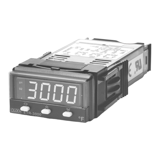
- Page 1 PK486-OMC59 SOFTWARE VERSION 33.16 and HIGHER Model ETR-3000 AUTOMATIC TUNING 1/32 DIN ® SMARTER LOGIC Controller ® INSTRUCTION MANUAL...
- Page 2 © Copyright June, 2004, Ogden Manufacturing Co., all rights reserved. No part of this publication may be reproduced, transmitted, transcribed or stored in a retrieval system. Similarly, this manual may not be translated into any language in any form by any means without written permission Ogden Manufacturing Co.
-
Page 3: Table Of Contents
Contents Page No Chapter 1 Overview Chapter 1 Overview 1-1 General Description ..............................4 1-2 Ordering Code ................................6 1-3 Programming Port ..............................7 1-4 Keys and Displays ..............................7 1-5 Menu Overview ................................9 1-6 Parameter Descriptions ............................10 Chapter 2 Installation Chapter 2 Installation 2-1 Unpacking ................................13 2-2 Mounting .................................13 2-3 Wiring precautions ..............................14... -
Page 4: Chapter 1 Overview
J, K, T, E, B, R, S, N, L without need to physically modify the unit. The input signal is digitized by using a 18-bit A to D converter. A fast sampling rate allows the ETR-3000 unit to control fast processes. - Page 5 Digital Communications Digital Communications The ETR-3000 can be equipped with an RS-485 or RS-232 interface card to provide digital communications. By using shielded twisted pair wire, at most 247 units can be connected together via an RS-485 interface to a host computer.
-
Page 6: Ordering Code
RS-232 interface ETR-Set = Configuration Software ETR-Set = Configuration Software CC94-1 = RS-232 Interface Cable ( 2M ) CC94-1 = RS-232 Interface Cable ( 2M ) CETR-9000-1 = Programming port cable for ETR-3000 CETR-9000-1 = Programming port cable for ETR-3000... -
Page 7: Programming Port
Front Terminal Panel Access Hole ETR-3000 Figure 1.2 Programming Port Overview Figure 1.2 Programming Port Overview A special connector can be used to connect to the programming port which is then connected to a PC for automatic configuration. It can also can be connected to an ATE system for automatic calibration and testing. - Page 8 : Characters Displayed by a Symbol Displays the program code of the product for 2.5 seconds. The ETR-3000 goes through an initial Power up self test in which it displays the Program code and version of the controller. The left diagram shows program no. 34 for an ETR-3000, version 16.
-
Page 9: Menu Overview
1- 5 Menu Overview 1- 5 Menu Overview Setup menu*1 Setup menu*1 User menu *1 User menu *1 Calibration Mode Calibration Mode 3 sec. 4 sec. 5 sec. 2 sec. Value LOCK Value INPT ADLO UNIT ADHI RTDL Manual Manual 3 sec. -
Page 10: Parameter Descriptions
1-6 Parameter Descriptions 1-6 Parameter Descriptions Parameter Default Parameter Description Range Notation Value 77.0 ° Set point for output 1 Low: SP1L High :SP1H 25.0 °C Set point for output 2 when 18.0° Low: -19999 High :45536 output 2 performs alarm 10.0 °C function or dwell timer : No parameters are locked... - Page 11 Parameter Default Parameter Description Range Notation Value : Reverse (heating ) control Output 1 function OUT1 : Direct (cooling) control : Relay : 0 - 1V : Solid state relay drive : 0 - 5V O1TY Output 1 signal type : Solid state relay : 1 - 5V : 0 - 10V...
- Page 12 Parameter Default Parameter Description Range Notation Value : No communication : Modbus RTU mode protocol :4-20mA retransmission output :0-20mA retransmission output COMM Communication function :0-5V retransmission output :1-5V retransmission output :0-10V retransmission output Address assignment of Low: 1 High: 255 ADDR digital communication : 2.4 Kbits/s...
-
Page 13: Chapter 2 Installation
Take the mounting clamp away and insert the controller into panel cutout. Install the mounting clamp back. Figure 2.1 Mounting Dimensions Figure 2.1 Mounting Dimensions MOUNTING 1 25/32” CLAMP (45mm) 7/8” ETR-3000 (22.2mm) SCREW Panel 31/64” 3 7/8” (12.5mm) (98.0mm) 13/32”... -
Page 14: Wiring Precautions
2 - 3 Wiring Precautions 2 - 3 Wiring Precautions Before wiring, verify the label for correct model number and options. Switch off the power while checking. Before wiring, verify the label for correct model number and options. Switch off the power while checking. Care must be taken to ensure that maximum voltage rating specified on the label are not exceeded. -
Page 15: Power Wiring
2-4 Power Wiring 2-4 Power Wiring The controller is designed to operate at 11-26 VAC / VDC or 90-250 VAC. Check that the installation voltage The controller is designed to operate at 11-26 VAC / VDC or 90-250 VAC. Check that the installation voltage corresponds with the power rating indicated on the product label before connecting power to the controller. -
Page 16: Control Output Wiring
2-7 Control Output Wiring 2-7 Control Output Wiring Figure 2.6 Figure 2.6 LOAD 120V/240VAC 120V/240VAC Output 1 Relay or Triac (SSR) to Drive Load Output 1 Relay or Triac (SSR) to Drive Load Main Supply Main Supply 120V /240V 120V /240V Main Supply Main Supply Three... -
Page 17: Alarm Wiring
120V /240V 120V /240V Main Supply Main Supply Figure 2.12 Figure 2.12 Three Three Output 2 Relay or Triac (SSR) to Drive Output 2 Relay or Triac (SSR) to Drive Phase Phase Three Phase Three Phase Contactor Contactor Heater Heater Delta Delta Power... -
Page 18: Data Communication
2-9 Data Communication 2-9 Data Communication RS-232 RS-485 ETR-3000 9-pin 9-pin Shielded Twisted-Pair Wire Shielded Twisted-Pair Wire RS-232 RS-232 port port RS-485 to RS-232 RS-485 to RS-232 ETR-3000 network adaptor network adaptor CC94-1 SNA10A or SNA10A or Figure 2.19 Figure 2.19... -
Page 19: Chapter 3 Programming
Chapter 3 Programming Chapter 3 Programming Press for 3 seconds and release to enter setup menu. Press to select the desired parameter. The display indicates the parameter symbol. Press to view or adjust the value of the selected parameter. 3-1 Lockout 3-1 Lockout There are four security levels can be selected by using LOCK parameter. -
Page 20: Control Outputs
3-3 Control Outputs 3-3 Control Outputs There are 4 kinds of control modes that can be configured as shown in Table 3.1 Table 3.1 Table 3.1 Heat-Cool Control Setup Value Table 3.1 Heat-Cool Control Setup Value Control OUT1 OUT2 O1HY O2HY Modes Heat only... - Page 21 Cool only control:ON-OFF control, P ( PD ) control and PID control can be used for cooling control. Set OUT1 Cool only control: to DIRT (direct action). The other functions for cool only ON-OFF control, cool only P ( PD ) control and cool only PID control are the same as the descriptions for heat only control except that the output variable (and action ) for the cool control is inverse to the heat control.
-
Page 22: Alarm
3-4 Alarm 3-4 Alarm Output 2 can be selected as an alarm output. There are 6 types of alarm functions and one dwell timer that can be selected. Four seperate alarm modes (ALMD) can additionally be applied to each alarm function. Alarm Failure Transfer Alarm Failure Transfer is activated as the unit enters... -
Page 23: Display Configuration
3-5 Display Configuration 3-5 Display Configuration The ETR-3000 can be configured to display the process value by selecting PV for DISP . To display the set point value select SP1 for DISP . Examples: If LOCK is set with NONE, OUT2 is set with DEHI, DISP is set with PV, set SEL1=SHIF, SEL2=ADDR. SEL3=PB,... -
Page 24: Dwell Timer
3-7 Dwell Timer 3-7 Dwell Timer Output 2 can be configured as dwell timer by selecting TIMR for OUT2. As the dwell timer is configured, the parameter SP2 is used for dwell time adjustment. The dwell time is measured in minute ranging from 0.1 to 4553.6 minutes. -
Page 25: Digital Filter
3- 9 Digital Filter 3- 9 Digital Filter In certain applications, the process value is too unstable to be read. To improve this, a programmable low pass filter In certain applications, the process value is too unstable to be read. To improve this, a programmable low pass filter incorporated in the controller can be used. -
Page 26: Auto-Tuning
3 -11 Auto-tuning 3 -11 Auto-tuning The auto-tuning process is performed at set point. The auto-tuning process is performed at set point. The process will oscillate around the set point during the tuning process. Set a set point to a lower value if The process will oscillate around the set point during the tuning process. -
Page 27: Manual Tuning
3 - 12 Manual Tuning 3 - 12 Manual Tuning In certain applications ( very few ) using auto-tuning to tune a process may be inadequate for the control requirement, then you can try manual tuning. If the control performance by using auto- tuning is still unsatisfactory, the following rules can be applied for further adjustment of PID values : SYMPTOM SOLUTION... -
Page 28: Manual Control
3 -13 Manual Control 3 -13 Manual Control Operation: To enable manual control, the LOCK parameter should be set to NONE, then press To enable manual control, the LOCK parameter should be set to NONE, then press several times several times then then (Heating output)or... -
Page 29: Chapter 4 Applications
An oven is designed to dry products at 150 degrees C for 30 minutes and then stay unpowered until the next batch is ready for baking. An is ready for baking. An ETR-3000 ETR-3000 equipped with a dwell timer is used for this purpose. A single phase system equipped with a dwell timer is used for this purpose. -
Page 30: Cool Only Control
4-2 Cool Only Control An ETR-3000 is used to control a refrigerator at a temperature below 0 ° . The temperature is lower than the An ETR-3000 is used to control a refrigerator at a temperature below 0 ° . The temperature is lower than the ambient, therefore a cooling action is required. -
Page 31: Heat-Cool Control
4-3 Heat-Cool Control 4-3 Heat-Cool Control An injection mold required to be controlled at 120 °C to ensure a consistent quality for the parts. An oil pipe is buried in the mold. An injection mold required to be controlled at 120 °C to ensure a consistent quality for the parts. An oil pipe is buried in the mold. Since plastics are injected at higher temperatures ( e.g. -
Page 32: Chapter 5 Calibration
Chapter 5 Calibration Chapter 5 Calibration Do not proceed through this section unless there is a definite need to re-calibrate the controller. Otherwise, all Do not proceed through this section unless there is a definite need to re-calibrate the controller. Otherwise, all previous calibration data will be lost. - Page 33 . Send a 100 ohms signal to the RTD input terminals . Send a 100 ohms signal to the RTD input terminals according to the connection shown below: according to the connection shown below: ETR-3000 100 ohms Figure 5.1 RTD Calibration Figure 5.1 RTD Calibration Press scroll key for at least 3 seconds .
- Page 34 Perform step 1 stated above , then press scroll key until the display shows Perform step 1 stated above , then press scroll key until the display shows . Press scroll key . Press scroll key for at least 3 seconds. The display will blink a moment and a new value is obtained. Otherwise , if the for at least 3 seconds.
-
Page 35: Chapter 6 Specifications
Chapter 6 Specifications Chapter 6 Specifications Power 90 ~ 250 VAC, 47 ~ 63 Hz, 10VA, 5W maximum 90 ~ 250 VAC, 47 ~ 63 Hz, 10VA, 5W maximum 11 ~ 26 VAC / VDC, 10VA, 5W maximum 11 ~ 26 VAC / VDC, 10VA, 5W maximum Input Resolution : Resolution :... - Page 36 Characteristics: Input Impedance Input Impedance Accuracy@ 25 C Accuracy@ 25 C Range Type -120 °C~1000 °C ( -184 °F~1832 °F ) -120 °C~1000 °C ( -184 °F~1832 °F ) ±2 °C ±2 °C 2.2 M 2.2 M -200 °C~1370 °C ( -328 °F~2498 °F ) -200 °C~1370 °C ( -328 °F~2498 °F ) ±2 °C ±2 °C...
- Page 37 Linear Output Linear Output Resolution : Resolution : 15 bits 15 bits Output Regulation : 0.02 % for full load change Output Regulation : 0.02 % for full load change Output Settling Time : 0.1 sec. ( stable to 99.9 % ) Output Settling Time : 0.1 sec.
- Page 38 Moldings : Moldings : Flame retardant polycarbonate Flame retardant polycarbonate Dimensions : Dimensions : ETR-3000 ETR-3000 -----50mm(W) X 26.5mm(H) X 110.5mm(D), 98 mm depth behind panel -----50mm(W) X 26.5mm(H) X 110.5mm(D), 98 mm depth behind panel Weight : Weight :...
-
Page 39: Error Codes
Notwithstanding the provisions of this WARRANTY AND LIMITATION Clause, it is specifically understood that Products and parts not manufactured and work not performed by Ogden are warranted only to the extent and in the manner that the same are warranted to Ogden by Ogden’s vendors, and then only to the extent that Ogden is reasonably able to enforce such warranty, it being understood Ogden to the extent and in the manner that the same are warranted to Ogden by Ogden’s vendors, and then only to the extent that Ogden is reasonably able to enforce such warranty, it being understood Ogden... - Page 40 64 West Seegers Road Arlington Heights, IL 60005 © Ogden Manufacturing Co. 2004 OGDEN, SMARTER LOGIC, ETR and (847) 593-8050 • Fax: (847) 593-8062 ETR-9000 are Registered Trademarks of www.ogdenmfg.com Ogden Manufacturing Co. MARCA REGISTRADA Specifications subject to change without notice.
Need help?
Do you have a question about the ETR-3000 and is the answer not in the manual?
Questions and answers