
Related Manuals for Ogden ETR-8300


Summary of Contents for Ogden ETR-8300
- Page 1 PK488-OMC57 Model ETR-8300 Microprocessor Based SMARTER LOGIC ® Temperature Control ® INSTRUCTION MANUAL...
- Page 2 Warning Symbol Warning Symbol This Symbol calls attention to an operating procedure, practice, or the like, which, if not correctly performed or This Symbol calls attention to an operating procedure, practice, or the like, which, if not correctly performed or adhered to, could result in personal injury or damage to or destruction of part or all of the product and system.
-
Page 3: Table Of Contents
CONTENTS Page No Page No Page No Page No Chapter 1 Overview Chapter 1 Overview 1-1 Features 1-1 Features 3-21 Signal Conditioner DC Power Supply 3-21 Signal Conditioner DC Power Supply 1-2 Ordering Code 1-2 Ordering Code 3-22 Manual Control 3-22 Manual Control 1-3 Programming Port and DIP Switch 1-3 Programming Port and DIP Switch... -
Page 4: Chapter 1 Overview
Chapter 1 Overview Chapter 1 Overview 1 1 Features 1 1 Features High accuracy 18-bit input A High accuracy 18-bit input A Unique Unique High accuracy 15-bit output D High accuracy 15-bit output D Valuable Valuable Fast input sample rate ( 5 times / second) Fast input sample rate ( 5 times / second) Two complexity level choices Two complexity level choices... - Page 5 Digital communications RS-485, RS-232 or 4 - 20 mA retransmission are available as an additional option. These options allow the ETR-8300 to be integrated with a supervisory additional option. These options allow the ETR-8300 to be integrated with a supervisory...
- Page 6 PID + Fuzzy Control has been proven to be an efficient method to improve process PID + Fuzzy Control has been proven to be an efficient method to improve process stability as shown by the comparison curves below: stability as shown by the comparison curves below: PID control with properly tuned PID + Fuzzy control Temperature...
-
Page 7: Ordering Code
CC94-1 = RS-232 Interface Cable (2M) CC94-1 = RS-232 Interface Cable (2M) Wave SSR AC Power Module Wave SSR AC Power Module = ETR-8300 User's Manual = ETR-8300 User's Manual VPFW100 =100 Amp. Variable Period Full VPFW100 =100 Amp. Variable Period Full... -
Page 8: Programming Port And Dip Switch
1 3 Programming Port and DIP Switch 1 3 Programming Port and DIP Switch Front Rear Terminal Panel ON DIP 1 2 3 4 Figure 1.3 Access Hole Figure 1.3 Access Hole Overview Overview Access Hole The programming port is used to connect to The programming port is used to connect to the P12A hand-held programmer for automatic the P12A hand-held programmer for automatic... -
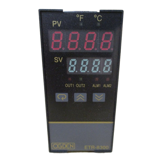
Page 9: Keys And Displays
3 Buttons for ease of control 3 Buttons for ease of control setup and set point adjustment. setup and set point adjustment. ETR-8300 Figure 1.4 Front Panel Description Figure 1.4 Front Panel Description 45536 will be displayed by: 45536 will be displayed by: Table 1.3 Character Legend... - Page 10 2.5 seconds. Out1 Out2 Alm1 Alm2 The left diagram shows program The left diagram shows program no. 3 ( for ETR-8300 ) with version no. 3 ( for ETR-8300 ) with version Program Version Program Version Program No.
-
Page 11: Menu Overview
1 5 Menu Overview 1 5 Menu Overview User User PV Value Menu Menu SV Value SEL1 SEL2 SEL3 SEL4 SEL5 for 3 Setup Setup seconds Menu Menu FUNC TIME COMM A1SP PROT A1DV ADDR A2SP BAUD A2DV Hand (Manual) Hand (Manual) DATA RAMP... -
Page 12: System Modes
1 6 System Modes 1 6 System Modes System Modes System Modes The controller performs close loop control under its normal control mode condition. The controller performs close loop control under its normal control mode condition. The controller will maintain its normal control mode when you are operating user menu, The controller will maintain its normal control mode when you are operating user menu, Sleep Mode : Sleep Mode :... -
Page 13: Parameter Description
1 7 Parameter Description 1 7 Parameter Description Table 1.4 Parameter Description Table 1.4 Parameter Description Display Display Parameter Parameter Contained Contained Basic Basic Parameter Parameter Default Default Range Format Format Description Description Function Function Notation Notation Value Value 100.0 °C Set point 1 High: SP1L... - Page 14 Table 1.4 Parameter Description ( continued 2/7 ) Table 1.4 Parameter Description ( continued 2/7 ) Display Display Parameter Parameter Basic Basic Parameter Parameter Default Default Contained Contained Range Format Format Description Description Function Function Notation Notation Value Value Address Assignment of Digital High: Low: ADDR...
- Page 15 Table 1.4 Parameter Description ( continued 3/7 ) Table 1.4 Parameter Description ( continued 3/7 ) Display Display Parameter Parameter Contained Contained Basic Basic Parameter Parameter Default Range Format Format Description Description Value Function Function Notation Notation N type thermocouple L type thermocouple PT 100 ohms DIN curve PT 100 ohms JIS curve...
- Page 16 Table 1.4 Parameter Description ( continued 4/7 ) Table 1.4 Parameter Description ( continued 4/7 ) Display Display Parameter Parameter Basic Basic Parameter Parameter Default Default Contained Contained Range Format Format Description Description Function Function Notation Notation Value Value 0 - 20 mA current module 0 - 1V voltage module 0 - 5V voltage module Output 1 Signal Type...
- Page 17 Table 1.4 Parameter Description ( continued 5/7 ) Table 1.4 Parameter Description ( continued 5/7 ) Display Display Parameter Parameter Contained Contained Basic Basic Parameter Parameter Default Default Range Format Format Description Description Function Function Notation Notation Value Value Alarm output OFF as unit fails Alarm 1 Failure Transfer A1FT Mode...
- Page 18 Table 1.4 Parameter Description ( continued 6/7 ) Table 1.4 Parameter Description ( continued 6/7 ) Display Display Parameter Parameter Contained Contained Basic Basic Parameter Parameter Default Default Range Format Format Description Description Function Function Notation Notation Value Value Use SP1 or SP2 (depends on EIFN) as set point Use minute ramp rate as set point Use hour ramp rate as set point...
- Page 19 Table 1.4 Parameter Description ( continued 7/7 ) Table 1.4 Parameter Description ( continued 7/7 ) Display Display Parameter Parameter Basic Basic Parameter Parameter Default Default Contained Contained Range Format Format Description Description Function Function Notation Notation Value Value Cold Junction Gain Low: -199.9 199.9...
- Page 20 B_TC S_TC Input Type J_TC K_TC T_TC E_TC R_TC 0 °C 0 °C -200 °C -250 °C -100 °C 0 °C -120 °C Range Low (32 °F) (-328 °F) (-418 °F) (-148 °F) (32 °F) (32 °F) (-184 °F) 1820 °C 1767.8 °C 1370 °C 400 °C...
-
Page 21: Chapter 2 Installation
Chapter 2 Installation Chapter 2 Installation Dangerous voltages capable of causing death are sometimes present Dangerous voltages capable of causing death are sometimes present in this instrument. Before installation or beginning any troubleshooting in this instrument. Before installation or beginning any troubleshooting procedures the power to all equipment must be switched off and isolated. -
Page 22: Wiring Precautions
2 3 Wiring Precautions 2 3 Wiring Precautions Before wiring, verify the label for correct model number and options. Switch off the power while checking. Care must be taken to ensure that maximum voltage rating specified on the label are not exceeded. It is recommended that the power supplied to of these units is protected by fuses or circuit breakers rated at the lowest value possible. -
Page 23: Power Wiring
2 4 Power Wiring 2 4 Power Wiring The controller is supplied with one of the following, either 11-26 VAC / VDC or The controller is supplied with one of the following, either 11-26 VAC / VDC or 90-264VAC. Check that the installation voltage corresponds with the power 90-264VAC. -
Page 24: Sensor Installation Guidelines
2 5 Sensor Installation Guidelines 2 5 Sensor Installation Guidelines Proper sensor installation can eliminate many problems in a control system. The probe should be placed so that it can detect any temperature change with minimal thermal lag. In a process that requires fairly constant heat output, the probe should be placed closed to the heater. -
Page 25: Thermocouple Input Wiring
2 6 Thermocouple Input Wiring 2 6 Thermocouple Input Wiring Thermocouple input connections are shown in Figure 2.5. The correct type of thermocouple extension lead-wire or compensating cable must be used for the entire distance between the controller and the thermocouple, ensuring that the correct polarity is observed throughout. -
Page 26: Rtd Input Wiring
2 7 RTD Input Wiring 2 7 RTD Input Wiring RTD connections are shown in Figure 2.6, with the compensating lead connected to RTD connections are shown in Figure 2.6, with the compensating lead connected to terminal 19. For two-wire RTD inputs, terminals 19 and 20 should be jumpered. The terminal 19. - Page 27 Figure 2.8 Figure 2.8 Input 1 Linear Current Wiring Input 1 Linear Current Wiring DIP Switch DIP Switch 0~20mA or 0~20mA or 4~20mA 4~20mA 0~1V, 0~5V 0~1V, 0~5V 1~5V, 0~10V 1~5V, 0~10V Figure 2.9 Figure 2.9 Input 2 Linear Voltage Wiring Input 2 Linear Voltage Wiring Figure 2.10 Figure 2.10...
-
Page 28: Ct / Heater Current Input Wiring
2 9 CT / Heater Current Input Wiring 2 9 CT / Heater Current Input Wiring Heater 1 Heater 1 Heater 2 Heater 2 Heater 3 Heater 3 Contactor Heater Supply Heater Supply Current Transformer Current Transformer CT94 1 Fuse Mains Mains supply... -
Page 29: Event Input Wiring
2 10 Event Input wiring 2 10 Event Input wiring Figure 2.13 Figure 2.13 Event Input Wiring Event Input Wiring Open Collector Open Collector Switch Input Switch Input Input Input The event input can accept a switch signal as well as an open collector signal. The The event input can accept a switch signal as well as an open collector signal. -
Page 30: Output 1 Wiring
2 11 Output 1 Wiring 2 11 Output 1 Wiring Max. 2A Max. 2A Resistive Resistive Load 120V/240V 120V/240V Mains Supply Mains Supply Figure 2.14 Figure 2.14 Output 1 Wiring Output 1 Wiring Relay Output Direct Drive Relay Output Direct Drive 120V /240V 120V /240V Mains Supply... - Page 31 0 - 20mA, 0 - 20mA, Load 4 - 20mA 4 - 20mA Maximum Load 500 ohms Maximum Load 500 ohms Linear Current Linear Current 0 - 1V, 0 - 5V 0 - 1V, 0 - 5V Load 1 - 5V, 0 - 10V 1 - 5V, 0 - 10V Minimum Load 10 K ohms Minimum Load 10 K ohms...
-
Page 32: Output 2 Wiring
2 12 Output 2 Wiring 2 12 Output 2 Wiring Max. 2A Max. 2A Resistive Resistive Load 120V/240V 120V/240V Mains Supply Mains Supply Relay Output Direct Drive Relay Output Direct Drive Figure 2.15 Figure 2.15 Output 2 Wiring Output 2 Wiring 120V /240V 120V /240V Mains Supply... - Page 33 0 - 20mA, 0 - 20mA, Load 4 - 20mA 4 - 20mA Maximum Load 500 ohms Maximum Load 500 ohms Linear Current Linear Current 0 - 1V, 0 - 5V 0 - 1V, 0 - 5V Load 1 - 5V, 0 - 10V 1 - 5V, 0 - 10V Minimum Load 10 K ohms Minimum Load 10 K ohms...
-
Page 34: Alarm 1 Wiring
2 13 Alarm 1 Wiring 2 13 Alarm 1 Wiring Max. 2A Max. 2A Resistive Resistive Load 120V/240V 120V/240V Mains Supply Mains Supply Relay Output Direct Drive Relay Output Direct Drive Figure 2.16 Figure 2.16 Alarm 1 Wiring Alarm 1 Wiring 120V /240V 120V /240V Mains Supply... -
Page 35: Alarm 2 Wiring
2 14 Alarm 2 Wiring 2 14 Alarm 2 Wiring Max. 2A Max. 2A Resistive Resistive Load 120V/240V 120V/240V Mains Supply Mains Supply Relay Output Direct Drive Relay Output Direct Drive Figure 2.17 Figure 2.17 Alarm 2 Wiring Alarm 2 Wiring 120V /240V 120V /240V Mains Supply... - Page 36 2 15 RS-485 2 15 RS-485 Figure 2.18 Figure 2.18 RS-485 Wiring RS-485 Wiring RS-485 to RS-232 RS-485 to RS-232 network adaptor network adaptor SNA10A or SNA10A or SNA10B SNA10B RS-232 Shielded Twisted-Pair Wire Shielded Twisted-Pair Wire DB-9 Serial DB-9 Serial Cable Cable Max.
- Page 37 To DTE ( PC ) RS-232 Port To DTE ( PC ) RS-232 Port 1 DCD 1 DCD ETR-8300 2 RD 2 RD 3 TD 3 TD Figure 2.21 Figure 2.21...
-
Page 38: Analog Retransmission
2 17 Analog Retransmission 2 17 Analog Retransmission Indicators Indicators PLC's PLC's 0 - 20mA, 0 - 20mA, Load Recorders Recorders 4 - 20mA 4 - 20mA Data loggers Data loggers Inverters etc. Inverters etc. Load Load The total effective resistance of serial The total effective resistance of serial loads can't exceed 500 ohms. -
Page 39: Programming Port
2 18 Programming Port 2 18 Programming Port See Figure 1.3 in Section 1-3 to find the programming port location. See Figure 1.3 in Section 1-3 to find the programming port location. Programmer Programmer connector and connector and ATE connector ATE connector Programmer Programmer... -
Page 40: Input
Chapter 3 Programming Basic Functions Chapter 3 Programming Basic Functions If you don't need: If you don't need: This unit provides a useful parameter " FUNC " which can be used to select This unit provides a useful parameter " FUNC " which can be used to select the function complexity level before setup. -
Page 41: Out1 & Out2 Types
IN1L IN1L : Selects the low scale value for the Linear type input 1. IN1L : Selects the low scale value for the Linear type input 1. Hidden if : Hidden if : T/C or RTD type is selected for IN1. T/C or RTD type is selected for IN1. -
Page 42: Rearrange User Menu
3 3 Rearrange User Menu SEL1 The ETR-8300 has the flexibility for you to select those parameters which The ETR-8300 has the flexibility for you to select those parameters which are most significant to your process. The selected parameters are then are most significant to your process. -
Page 43: Heat Only Control
3 4 Heat Only Control 3 4 Heat Only Control Setup ON-OFF : Setup ON-OFF : Heat Only ON-OFF Control : Select REVR for OUT1, Set PB1 to 0, SP1 is used Heat Only ON-OFF Control : Select REVR for OUT1, Set PB1 to 0, SP1 is used OUT1 = OUT1 = to adjust the set point value, O1HY is used to adjust the dead band for ON-OFF... -
Page 44: Cool Only Control
3 5 Cool Only Control 3 5 Cool Only Control Setup Cool Control : Setup Cool Control : ON-OFF control, P (PD) control and PID control can be used for cooling ON-OFF control, P (PD) control and PID control can be used for cooling OUT1 = OUT1 = applications. -
Page 45: Heat - Cool Control
3 6 Heat-Cool Control 3 6 Heat-Cool Control The Heat-Cool Control can use one of The Heat-Cool Control can use one of combinations of control modes. Setup of parameters for each control combinations of control modes. Setup of parameters for each control mode are shown in the following table. - Page 46 CPB Programming : The cooling proportional band is measured by a % of PB with range 1~255. Initially set set the CPB Programming : The cooling proportional band is measured by a % of PB with range 1~255. Initially set set the CPB to 100% and examine the cooling effect.
-
Page 47: Dwell Timer
3 7 Dwell Timer 3 7 Dwell Timer Alarm 1 or alarm 2 can be configured as a dwell timer by selecting TIMR for Alarm 1 or alarm 2 can be configured as a dwell timer by selecting TIMR for A1FN or A2FN, but not both, or A1FN or A2FN, but not both, or Er07... -
Page 48: Process Alarms
3 8 Process Alarms 3 8 Process Alarms A process alarm allows for an absolute trigger level or specific temperature A process alarm allows for an absolute trigger level or specific temperature to be monitored. When the to be monitored. When the process exceeds that absolute trigger level process exceeds that absolute trigger level an alarm occurs. - Page 49 (3-8 Pg. 1 of 2) (3-8 Pg. 1 of 2) A1SP = 200 A1SP = 200 A1HY = 10.0 A1HY = 10.0 A1MD = LTCH A1MD = LTCH A1FN = PV1.H A1FN = PV1.H Process proceeds Process proceeds Figure 3.6 Figure 3.6 Latching Process Alarm Latching Process Alarm...
-
Page 50: Deviation Alarms
3 9 Deviation Alarm 3 9 Deviation Alarm A deviation alarm alerts the user when the process deviates too far from set A deviation alarm alerts the user when the process deviates too far from set 2 Types of Deviation Alarms : 2 Types of Deviation Alarms : point. -
Page 51: Deviation Band Alarms
3 10 Deviation Band Alarm 3 10 Deviation Band Alarm A deviation band alarm presets two reference levels relative to the set point. A deviation band alarm presets two reference levels relative to the set point. 2 Types of Deviation Band Alarms: 2 Types of Deviation Band Alarms: There are two types of deviation band alarms which can be configured. -
Page 52: Heater Break Alarm 1
3 11 Heater Break Alarm 3 11 Heater Break Alarm Heater Break Alarm 1 Heater Break Alarm 1 A current transformer ( parts No. A current transformer ( parts No. CT94-1 CT94-1 ) should be installed to detect the ) should be installed to detect the Setup : IN2 = CT Setup : IN2 = CT heater current if a heater break alarm is required. -
Page 53: Loop Break Alarm 1
3 12 Loop Break Alarm 3 12 Loop Break Alarm Loop Break Alarm 1 Loop Break Alarm 1 Under the parameter A1FN, select LB if alarm 1 is required to act as a loop Under the parameter A1FN, select LB if alarm 1 is required to act as a loop break alarm. -
Page 54: Sensor Break Alarm
3 13 Sensor Break Alarm 3 13 Sensor Break Alarm Alarm 1 or alarm 2 can be configured as a sensor break alarm by selecting Alarm 1 or alarm 2 can be configured as a sensor break alarm by selecting Sensor Break Alarm 1 Sensor Break Alarm 1 SENB... -
Page 55: Pv1 Shift
3 15 PV1 Shift 3 15 PV1 Shift In certain applications it is desirable to shift the controller display value from In certain applications it is desirable to shift the controller display value from its actual value. This can be easily accomplished by using the PV1 shift its actual value. -
Page 56: Failure Transfer
3 16 Failure Transfer 3 16 Failure Transfer Failure Mode Occurs as : Failure Mode Occurs as : The controller will enter The controller will enter failure mode failure mode as one of the following conditions occurs: as one of the following conditions occurs: 1. -
Page 57: Bumpless Transfer
3 17 Bumpless Transfer 3 17 Bumpless Transfer The bumpless transfer function is available for output 1 and output 2 ( provided The bumpless transfer function is available for output 1 and output 2 ( provided Bumpless Transfer Setup : Bumpless Transfer Setup : that OUT2 is configured as COOL ). -
Page 58: Self-Tuning
3 18 Self 3 18 Self tuning tuning Self-tuning which is designed using an Self-tuning which is designed using an innovative algorithm which innovative algorithm which provides an provides an Self-tune Menu Self-tune Menu alternative option for tuning the controller. It is activated as soon as “YES” is alternative option for tuning the controller. -
Page 59: Auto-Tuning
3 19 Auto 3 19 Auto tuning tuning The auto-tuning process will oscillate around the set point during the The auto-tuning process will oscillate around the set point during the tuning process. Set a set point to a lower value if overshooting beyond tuning process. - Page 60 Auto-tuning Auto-tuning Auto-tuning Auto-tuning Begins Begins Complete Complete Waiting Waiting Warm-up Warm-up Cycle Cycle Learning Cycle Learning Cycle New PID Cycle New PID Cycle Cycle Cycle =2 Integral =2 Integral Time Time Figure 3.22 Figure 3.22 Set Point Set Point Auto-tuning Procedure Auto-tuning Procedure Pre-tune Stage...
-
Page 61: Manual Tuning
3 20 Manual Tuning 3 20 Manual Tuning In certain applications ( very few ) using both self-tuning and auto-tuning to In certain applications ( very few ) using both self-tuning and auto-tuning to tune a process may be inadequate for the control requirement, then you can tune a process may be inadequate for the control requirement, then you can try manual tuning. - Page 62 The PBu is called the The PBu is called the Ultimate P Band Ultimate P Band and the period of oscillation Tu is called and the period of oscillation Tu is called Ultimate Period Ultimate Period in the flow chart of Figure 3.23 . When this occurs, the in the flow chart of Figure 3.23 .
- Page 63 I action I action TI too high TI too high Figure 3.25 (Continued ) Figure 3.25 (Continued ) Set point Set point Effects of PID Adjustment Effects of PID Adjustment Perfect TI too low TI too low Time D action D action TD too low TD too low...
-
Page 64: Signal Conditioner Dc Power Supply
3 21 Signal Conditioner DC Power Supply 3 21 Signal Conditioner DC Power Supply Three types of isolated DC power supplies are available to supply an external transmitter Three types of isolated DC power supplies are available to supply an external transmitter or sensor. -
Page 65: Manual Control
3 22 Manual Control 3 22 Manual Control The manual control may be used for the following The manual control may be used for the following purposes purposes ( 1 ) To test the process characteristics to obtain a step response as well as an ( 1 ) To test the process characteristics to obtain a step response as well as an impulse response and use this data for tuning a controller. -
Page 66: Display Mode
3 23 Display Mode 3 23 Display Mode Operation Press Press several times until several times until ( Display ) appears on the display. ( Display ) appears on the display. Then press Then press to enter the display mode. You can select more parameters to to enter the display mode. -
Page 67: Heater Current Monitoring
3 24 Heater Current Monitoring 3 24 Heater Current Monitoring Accessory Installed: Accessory Installed: A current transformer, CT94-1, needs to be installed to measure the heater A current transformer, CT94-1, needs to be installed to measure the heater CT94-1 CT94-1 current. -
Page 68: Chapter 4 Programming The Full Function
Chapter 4 Programming the Full Function Chapter 4 Programming the Full Function 4 1 Event Input 4 1 Event Input Refer to Section 2-10 for wiring an event input. Refer to Section 2-10 for wiring an event input. The Event input accepts a digital type signal. The Event input accepts a digital type signal. -
Page 69: Second Set Point
SP2F Function: Define format of SP2 value . If SP2F in the setup menu is SP2F Function: Define format of SP2 value . If SP2F in the setup menu is SP2F=Format of SP2 Value SP2F=Format of SP2 Value selected with ACTU, the event input function will use SP2 value for its second selected with ACTU, the event input function will use SP2 value for its second ACTU: SP2 is an actual value ACTU: SP2 is an actual value... -
Page 70: Second Pid Set
In certain applications the process characteristics are strongly related to the In certain applications the process characteristics are strongly related to the ETR process value. The ETR-8300 provides two set of PID values. When the ETR process value. The ETR-8300 provides two set of PID values. When the... -
Page 71: Ramp & Dwell
4 4 Ramp & Dwell 4 4 Ramp & Dwell Ramp The ramping function is performed during power up as well as any time the set The ramping function is performed during power up as well as any time the set SPMD Choose SPMD Choose point is changed. - Page 72 Once the timer output is energized it will remain unchanged until power down Once the timer output is energized it will remain unchanged until power down or an appropriate event input function is applied. or an appropriate event input function is applied. Error Code.
-
Page 73: Remote Set Point
When the SPMD parameter is set to selecting PV1 or PV2, it will enable the ETR-8300 to accept a remote set point signal. If PV1 is selected for SPMD, the ETR-8300 to accept a remote set point signal. If PV1 is selected for SPMD, the... -
Page 74: Differential Control
4 6 Differential Control 4 6 Differential Control In certain applications it is necessary to control a second process such that its In certain applications it is necessary to control a second process such that its Setup process value always deviates from the first process with a constant value. To process value always deviates from the first process with a constant value. -
Page 75: Output Power Limits
4 7 Output Power Limits 4 7 Output Power Limits In certain system the heater ( or cooler ) is over-designed such that the In certain system the heater ( or cooler ) is over-designed such that the Menu process is too heavily heated or cooled. To avoid an excessive overshoot process is too heavily heated or cooled. -
Page 76: Data Communication
Using a PC for data communication is the most economic way. The signal is transmitted and received through the PC communication Port ( generally RS- transmitted and received through the PC communication Port ( generally RS- Order ETR-8300-XXXXXX1 Order ETR-8300-XXXXXX1 232 ). Since a standard PC can't support RS-485 port, a network adaptor 232 ). -
Page 77: Analog Retransmission
4 9 Analog Retransmission Setup Menu Setup Menu The Analog Retransmission is available for model number ETR-8300-XXXXXXN The Analog Retransmission is available for model number ETR-8300-XXXXXXN Where N 3,4 or 5. See Ordering Code in Where N 3,4 or 5. See Ordering Code in section 1-2. -
Page 78: Digital Filter
4 10 Digital Filter 4 10 Digital Filter Menu In certain applications, the process value is too unstable to be read. To In certain applications, the process value is too unstable to be read. To improve this a programmable low pass filter incorporated in the improve this a programmable low pass filter incorporated in the ETR 8300 ETR 8300... -
Page 79: Sleep Mode
4 11 Sleep Mode 4 11 Sleep Mode Sleep Mode Features: Sleep Mode Features: Enter Enter Sleep Mode: Sleep Mode: FUNC selects FULL to provide full function. FUNC selects FULL to provide full function. Shut off display Shut off display SLEP selects YES to enable the sleep mode. -
Page 80: Pump Control
ETR-8300 can realize such an application. To achieve this, set provided by the ETR-8300 can realize such an application. To achieve this, set... -
Page 81: Remote Lockout
Programming Guide: Programming Guide: 1. Perform auto-tuning to the system under such a condition that the material 1. Perform auto-tuning to the system under such a condition that the material ( ie. pressure ) is exhausted at typical rate. A typical value for PB1 is about ( ie. -
Page 82: Chapter 5 Applications
Here is an example: solution. Here is an example: ETR-8300-4137XXX Kg/cm Pressure Pressure Reservoir Reservoir Out1 Out2 Alm1 Alm2 Figure 5.1... - Page 83 Set the following parameters in the setup menu: Set the following parameters in the setup menu: FUNC=FULL FUNC=FULL COMM: optional COMM: optional IN1=4-20 IN1=4-20 IN1U=PU IN1U=PU DP1=2-DP DP1=2-DP IN1L=0 IN1L=0 IN1H=20.00 IN1H=20.00 IN2=NONE IN2=NONE OUT1=REVR OUT1=REVR O1TY=4-20 O1TY=4-20 O1FT=0 O1FT=0 OUT2=DCPS OUT2=DCPS A1FN: optional...
-
Page 84: Variable Period Full Wave Ssr ( Vpfw Ssr )
5 2 Variable Period Full Wave SSR ( VPFW SSR ) 5 2 Variable Period Full Wave SSR ( VPFW SSR ) VPFW SSR is a variable period full wave solid-state relay. It can provide a zero VPFW SSR is a variable period full wave solid-state relay. It can provide a zero cross output with superior control compared to a conventional SSR with a cross output with superior control compared to a conventional SSR with a fixed time base. - Page 85 Longer Shorter Output 1 and output 2 of the ETR-8300 can be connected to VPFW SSR Output 1 and output 2 of the ETR-8300 can be connected to VPFW SSR directly provided that a pulsed voltage drive output (ETR-8300-XX2XXXX or directly provided that a pulsed voltage drive output (ETR-8300-XX2XXXX or ETR-8300-XXX2XXX ) is ordered.
-
Page 86: Heat Only Control
Oven Out1 Out2 Alm1 Alm2 Figure 5.5 Figure 5.5 Heater Heat Control Example Heat Control Example ETR-8300 Mains Mains Supply Supply OUT1 Timer ( ALM1 ) Timer ( ALM1 ) To achieve this function set the following parameters in the setup menu. -
Page 87: Cool Only Control
5 4 Cool Only Control ON-OFF control ON-OFF control An ETR-8300 is used to control a refrigerator at a temperature below 0 °C. To An ETR-8300 is used to control a refrigerator at a temperature below 0 °C. To Direct Control Action... -
Page 88: Heat - Cool Control
Injection Mold Injection Mold Plastics 120 C 120 C Figure 5.7 Figure 5.7 Heat-Cool Control Example Heat-Cool Control Example Pump Pump Oil Tank Oil Tank Freezer Heater Heater Supply Supply 4-20 mA 4-20 mA OUT2 OUT1 Out1 Out2 Alm1 Alm2 ETR-8300... - Page 89 The PID Heat-Cool is used for the above example. The PID Heat-Cool is used for the above example. Key Menu Key Menu To achieve this set the following parameters in the Setup Menu: To achieve this set the following parameters in the Setup Menu: FUNC FUNC FUNC=BASC...
-
Page 90: Ramp & Dwell
Freezer Heater Inverter Mains Mains AC Relay AC Relay Cycle Timer Cycle Timer TIME=60.0 (minutes ) TIME=60.0 (minutes ) SP1=60.0 °C SP1=60.0 °C SP2=-10.0 °C SP2=-10.0 °C ETR-8300 CPB=100 (%) CPB=100 (%) RAMP=14.0 ( °C/minute ) RAMP=14.0 ( °C/minute ) - Page 91 60 minutes 60 minutes 60 minutes 60 minutes 60 C 60 C 60 C 60 C Figure 5.9 Figure 5.9 -10 C -10 C -10 C -10 C Temperature Profile Temperature Profile of Chamber of Chamber minutes minutes minutes minutes 65 minutes 65 minutes 5 minutes...
-
Page 92: Remote Set Point
If you order an ETR-8300 with a retransmission unit for the master controller, If you order an ETR-8300 with a retransmission unit for the master controller,... -
Page 93: Differential Control
Out1 Out2 Alm1 Alm2 Outlet ETR-8300 Adjust SP1( here is 1.00 ) to control the difference between PV1 and PV2. Choosing P1-2 Adjust SP1( here is 1.00 ) to control the difference between PV1 and PV2. Choosing P1-2 for PVMD, the PV display will show the difference value ( PV1-PV2 ) between PV1 and for PVMD, the PV display will show the difference value ( PV1-PV2 ) between PV1 and PV2, and this value will be stabilized to the set point ( here is 1.00 ). -
Page 94: Dual Set Point / Pid
5 9 Dual Set Point / PID 5 9 Dual Set Point / PID The ETR-8300 will switch between the two PID sets based on the process The ETR-8300 will switch between the two PID sets based on the process value, the set point or the event input. - Page 95 Example 2: Dual Set Point / PID Example 2: Dual Set Point / PID A heat treating furnace is required to harden a mold at a high temperature A heat treating furnace is required to harden a mold at a high temperature (1000 °C) for 30 minutes, then the mold is cooled down with a programmable (1000 °C) for 30 minutes, then the mold is cooled down with a programmable ramp ( 20 °C / minute ) toward a lower set point ( 200 °C ).
- Page 96 A cost effective solution for the above application is to use 80 productivity. A cost effective solution for the above application is to use 80 units of the units of the ETR-8300 / ETR-4300-XXXXXX1 ETR-8300 / ETR-4300-XXXXXX1 plus an plus an...
- Page 97 Setup Setup Menu Setup Menu First, Enter the setup mode to configure each First, Enter the setup mode to configure each ETR 8300 ETR 8300 . Choose FULL for . Choose FULL for FUNC FUNC FUNC, 485 for COMM, RTU for PROT and select an unequal address ( ADDR ) FUNC, 485 for COMM, RTU for PROT and select an unequal address ( ADDR ) COMM COMM...
- Page 98 He/She uses FUNC FUNC an ETR-8300 to control the temperature of the solution under test. A test report an ETR-8300 to control the temperature of the solution under test. A test report COMM...
-
Page 99: Retransmit
5 12 Retransmit 5 12 Retransmit An air-conditioned room uses two units of the ETR-8300 to control its An air-conditioned room uses two units of the ETR-8300 to control its temperature and humidity. The temperature and humidity are required to be temperature and humidity. -
Page 100: Chapter 6 Calibration
Chapter 6 Calibration Chapter 6 Calibration Do not proceed through this section unless there is a definite need to Do not proceed through this section unless there is a definite need to re-calibrate the controller. Otherwise, all previous calibration data will be re-calibrate the controller. - Page 101 RTD input RTD input and 20 according to the connection shown below: and 20 according to the connection shown below: 100 ohms ETR-8300 Figure 6.1 Figure 6.1 RTD Calibration RTD Calibration Press scroll key for at least 3 seconds . The display will blink a Press scroll key for at least 3 seconds .
- Page 102 Note that a K type TC input TC input thermocouple must be used. thermocouple must be used. 5520A 5520A Calibrator Calibrator ETR-8300 Figure 6.2 Figure 6.2 K-TC Cold Junction Cold Junction Calibration Setup Calibration Setup Stay at least...
- Page 103 The unit under calibration is powered in a still-air room with The unit under calibration is powered in a still-air room with temperature temperature 25±3 °C 25±3 °C . Stay at least 20 minutes for warming up. The . Stay at least 20 minutes for warming up. The DIP Switch is located at TC input .
-
Page 104: Chapter 7 Error Codes & Troubleshooting
Chapter 7 Error Codes & Troubleshooting Chapter 7 Error Codes & Troubleshooting This procedure requires access to the circuitry of a live power unit. Dangerous accidental contact with line voltage This procedure requires access to the circuitry of a live power unit. Dangerous accidental contact with line voltage is possible. - Page 105 Table 7.1 Error Codes and Corrective Actions Table 7.1 Error Codes and Corrective Actions Display Error Error Description Corrective Action Symbol Code Illegal setup values been used: PV1 is used for both PVMD Check and correct setup values of PVMD and SPMD. PV and SPMD.
- Page 106 Table 7.2 Common Failure Causes and Corrective Actions Table 7.2 Common Failure Causes and Corrective Actions Symptom Probable Causes Corrective Actions - No power to instrument - Check power line connections 1) LED's will not light - Power supply defective - Replace power supply board 2) Some segments of the display or - Replace LED display or LED lamp...
-
Page 107: Chapter 8 Specifications
Chapter 8 Specifications Chapter 8 Specifications Power Input 2 Input 2 90 264 VAC, 47 63 Hz, 15VA, 7W maximum 90 264 VAC, 47 63 Hz, 15VA, 7W maximum Resolution : Resolution : 18 bits 18 bits 11 26 VAC / VDC, 15VA, 7W maximum 11 26 VAC / VDC, 15VA, 7W maximum Sampling Rate : Sampling Rate :... - Page 108 Linear Output Linear Output Resolution : Resolution : 15 bits 15 bits Resolution : Resolution : 15 bits 15 bits Accuracy : Accuracy : ±0.05 % of span ±0.0025 %/ °C ±0.05 % of span ±0.0025 %/ °C Output Regulation : Output Regulation : 0.01 % for full load change 0.01 % for full load change...
- Page 109 Environmental & Physical Environmental & Physical Operating Temperature : Operating Temperature : -10 °C to 50 °C -10 °C to 50 °C Storage Temperature : Storage Temperature : -40 °C to 60 °C -40 °C to 60 °C Humidity : Humidity : 0 to 90 % RH ( non-condensing ) 0 to 90 % RH ( non-condensing )
-
Page 110: Menu Existence Conditions
A 1 Menu Existence Coditions A 1 Menu Existence Coditions Menu Existence Conditions Table Menu Existence Conditions Table Parameter Parameter Menu Existence Conditions Existence Conditions Notation Notation Exists unconditionally Exists unconditionally TIME Exists if A1FN selects TIMR or A2FN selects TIMR Exists if A1FN selects TIMR or A2FN selects TIMR A1SP Exists if A1FN selects PV1H, PV1L, PV2H, PV2L, P12H, P12L, D12H or D12L... - Page 111 Menu Existence Conditions Table ( continued 2/3 ) Menu Existence Conditions Table ( continued 2/3 ) Parameter Parameter Menu Existence Conditions Existence Conditions Notation Notation FUNC Exists unconditionally Exists unconditionally COMM Exists if FUNC selects FULL Exists if FUNC selects FULL PROT ADDR BAUD...
- Page 112 Menu Existence Conditions Table ( continued 3/3 ) Menu Existence Conditions Table ( continued 3/3 ) Parameter Parameter Menu Existence Conditions Existence Conditions Notation Notation A1FN Exists unconditionally Exists unconditionally Exists if A1FN selects DEHI, DELO, DBHI, DBLO, PV1H, PV1L, PV2H, PV2L, P12H, P12L, Exists if A1FN selects DEHI, DELO, DBHI, DBLO, PV1H, PV1L, PV2H, PV2L, P12H, P12L, A1MD D12H, D12L, LB or SENB...
-
Page 113: Factory Menu Description
A 2 Factory Menu Description A 2 Factory Menu Description Parameter Parameter Display Display Default Default Parameter Description Parameter Description Range Notation Notation Format Format Value Value Low: High: EROR Current Error Code Program Identification Code Contains Program Low: High: PROG 15.99 Number and Version Number... - Page 114 Parameter Parameter Display Display Default Default Parameter Description Parameter Description Range Notation Notation Format Format Value Value Working Hour Value High: 65535 Hours HOUR Low: High: Fractional Hour Value Low: 0.9 Hour HRLO Historical Error Record 1 Low: FFFF High: ERR1 High: Low:...
-
Page 115: Glossary
A 3 Glossary A 3 Glossary Abosolute zero: The lowest theoretical temperature. At Abosolute zero: The lowest theoretical temperature. At Automatic reset (Integral): The integral function of a Automatic reset (Integral): The integral function of a absolute zero, a body would have no molecular motion absolute zero, a body would have no molecular motion control that automatically compensates for the control that automatically compensates for the... - Page 116 Dead band: 1. For chart recorders: the minimum change Dead band: 1. For chart recorders: the minimum change CE: A mark that designates compliance with European CE: A mark that designates compliance with European Union (EU) requirements for products sold in Europe. Union (EU) requirements for products sold in Europe.
- Page 117 Electromagnetic Compatibility (EMC): A system meets Electromagnetic Compatibility (EMC): A system meets fpm: Flow velocity in feet per minute. fpm: Flow velocity in feet per minute. three requirements: 1. It does not cause interference three requirements: 1. It does not cause interference fps: Flow velocity in feet per second.
- Page 118 Hi-Pot test : To apply a high voltage to an electrical Hi-Pot test : To apply a high voltage to an electrical Kilo: The prefix for one thousand (K). Kilo: The prefix for one thousand (K). conductor to test the surrounding insulation. conductor to test the surrounding insulation.
- Page 119 NEMA 4X: A front panel rating designating the control as NEMA 4X: A front panel rating designating the control as Proportional control mode: When process temperature Proportional control mode: When process temperature washdown capable and corrosion resistance. washdown capable and corrosion resistance. approaches set point and enters the proportional band, approaches set point and enters the proportional band, the output is switched on and off at the established...
- Page 120 RFI: Radio frequency interference. RFI: Radio frequency interference. Surge current: A current of short duration occurring when Surge current: A current of short duration occurring when power is initially applied to capacitive or resistive loads, power is initially applied to capacitive or resistive loads, RS232 or RS485 output signal: A serial interface suitable RS232 or RS485 output signal: A serial interface suitable usually lasting no more than several cycles.
- Page 121 TTL: Transistor-to-transistor logic. A form of solid state TTL: Transistor-to-transistor logic. A form of solid state logic which uses only transistors to form the logic logic which uses only transistors to form the logic gates. gates. UL: Underwriters Laboratories, Inc. An independent UL: Underwriters Laboratories, Inc.
-
Page 122: Index
A 4 Index A 4 Index A1DV: 11, 13, 18, 47, 48, 50, 51, 53 A1DV: 11, 13, 18, 47, 48, 50, 51, 53 Auto-tuning: 11, 12, 43, 45, 46, 58 Auto-tuning: 11, 12, 43, 45, 46, 58 CT: 4, 20, 22, 28, 40, 52, 67, 102 CT: 4, 20, 22, 28, 40, 52, 67, 102 54, 110 54, 110... - Page 123 FILT: 11, 17, 40, 78, 80, 81, 83, 108 FILT: 11, 17, 40, 78, 80, 81, 83, 108 Linear current: 15, 26, 27, 31, 33, 41 Linear current: 15, 26, 27, 31, 33, 41 OUT2: 11, 16, 22, 41, 45, 48, 50, OUT2: 11, 16, 22, 41, 45, 48, 50, 51, 53, 54, 56, 57, 64, 65, 75, 51, 53, 54, 56, 57, 64, 65, 75,...
- Page 124 PVHI: 9, 11, 19, 66 PVHI: 9, 11, 19, 66 Second PID: 40, 68, 69, 70, 94, 95 Second PID: 40, 68, 69, 70, 94, 95 SP2: 11, 13, 17, 18, 20, 40, 42, 48, SP2: 11, 13, 17, 18, 20, 40, 42, 48, 68, 69, 72, 74, 80, 81, 83, 90, 91, 68, 69, 72, 74, 80, 81, 83, 90, 91, PV1: 11, 13, 17, 19, 20, 40, 41, 45,...
-
Page 125: Memo
A 5 Memo A 5 Memo Use the following Table as a master copy for your settings. Use the following Table as a master copy for your settings. Contained Contained Parameter Parameter Display Display Contained Contained Parameter Parameter Display Display Your setting Your setting Your setting... - Page 126 Contained Contained Parameter Parameter Display Display Contained Contained Parameter Parameter Display Display Your setting Your setting Your setting Your setting Notation Notation Format Format Notation Notation Format Format OUT2 O2TY CYC2 O2FT CJTL Calibra- tion A1FN Mode Menu A1MD REF1 A1FT A2FN MA1G...
-
Page 127: Warranty
Notwithstanding the provisions of this WARRANTY AND LIMITATION Clause, it is specifically understood that Products and parts not manufactured and work not performed by Ogden are warranted only to the extent and in the manner that the and parts not manufactured and work not performed by Ogden are warranted only to the extent and in the manner that the same are warranted to Ogden by Ogden’s vendors, and then only to the extent that Ogden is reasonably able to enforce... - Page 128 64 West Seegers Road © Ogden Manufacturing Co. 2004 Arlington Heights, IL 60005 OGDEN, SMARTER LOGIC, ETR, ETR-4300, ETR-8300 and ETR-NET (847) 593-8050 •Fax: (847) 593-8062 are registered trademarks of www.ogdenmfg.com Ogden Manufacturing Co. MARCA REGISTRADA Specifications subject to change without notice.
Need help?
Do you have a question about the ETR-8300 and is the answer not in the manual?
Questions and answers