
Related Manuals for Incite Fire Sigma CP


Summary of Contents for Incite Fire Sigma CP
- Page 1 Conventional Fire Control Panel AFP-2516 Operation and Maintenance Manual SIGMA-CP Issue 1 November 2011...
-
Page 2: Table Of Contents
Index Page Warning ......................... 4 Introduction ........................5 Safety and Mounting ......................5 Safety ............................ 5 Mounting ..........................6 Technical specification ..................... 7 Using intrinsically safe barriers..................9 Control panel fascia ....................... 10 Connecting to the circuit board ..................11 Software revision number .................... - Page 3 Processor reset switch ....................20 Internal indications – troubleshooting ................20 20.1 Mains fail ..........................20 20.2 Batt fail ..........................20 20.3 CPU fault ..........................20 20.4 Aux 24V fault ........................20 20.5 Batt low ..........................20 20.6 Earth fault ..........................20 20.7 Sys fuse fault ........................
-
Page 4: Warning
Warning Sounders can only be used on detection circuits if Hochiki YBO-R/6PA detector bases are used. To disable sounders on detector all lines, ensure that configuration mode 25 is not set. To disable sounders on individual detector circuits, set configuration mode 25 and disable individual circuits through the setting of C1 to C8.See Section 17Table 8. -
Page 5: Introduction
Introduction The SIGMA CP conventional fire alarm control panel is designed to comply with AS7240-2 and AS7240-4 Fire Detection and Fire Alarm systems - Control and Indicating Equipment. The control panel has an integral, mains powered battery charger and power supply designed in accordance with the requirements of AS7240-4. -
Page 6: Mounting
Mounting The control panel should be mounted on a dry, flat surface, at eye height to the display and in a level position such that the enclosure is not distorted. Screws or bolts of a minimum of 5mm diameter must be used to mount the enclosure in all four mounting points. -
Page 7: Technical Specification
Technical specification Table 1 Electrical Specifications Mains supply 230V AC +10% - 15% (100 Watts maximum) Mains supply fuse 1.6Amp (F1.6A L250V) Replace only with similar type Power supply rating 3 Amps total including battery charge 28V +/ 2V Maximum ripple current 1.5 Volts Output voltage 18.5 to 29V DC +/- 2%... - Page 8 Table 4 Compatible Detectors Model Type Manufacturer Maximum Number per zone SLV-AS OPTICAL HOCHIKI DCD-A HEAT HOCHIKI DCD-C HEAT HOCHIKI DFJ-60B HEAT HOCHIKI DFJ-90D HEAT HOCHIKI DFG-60BLKJ HEAT HOCHIKI DRD-AS FLAME HOCHIKI SPC-AS BEAM HOCHIKI Table 5 Compatible detector bases and call points Model Type Manufacturer...
-
Page 9: Using Intrinsically Safe Barriers
Using intrinsically safe barriers SIGMA CP control panels support the use of I.S. barriers for connecting to equipment in hazardous areas. Only certified detectors, call points and sounders may be used in hazardous areas and these must be connected to the control panel via a compatible I.S. barrier as listed in Table 7. -
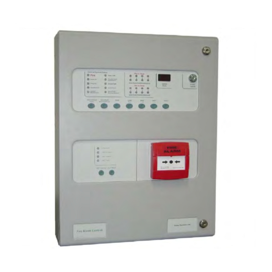
Page 10: Control Panel Fascia
Control panel fascia In addition to the mandatory controls and indications required by the AS7240-2 standard, two seven- segment LED displays and MODE, SELECT and ENTER buttons are provided to allow easy entry and storage of codes to configure the control panel to suit the requirements of the installation. Opening the fascia The fascia of the control panel is held in place by a screw on the right hand side. -
Page 11: Connecting To The Circuit Board
The space at the bottom of the enclosure is largely occupied by the standby batteries so this must be borne in mind when considering cable entries. CORRECT INCORRECT INCORRECT Software revision number New features may be added to Sigma CP fire control panels from C 34 C 106 C 107 C 23 C 22 C 21... -
Page 12: Detection Zone Wiring
10 Detection zone wiring The detection zones provide a nominal 24V DC to power compatible conventional detectors and call points. The wiring is monitored for open and short circuit fault conditions. The 6K8 end of line monitoring resistors that are factory fitted to the control panel’s terminals must be removed and placed across the last device that is wired to the zone circuit. -
Page 13: Sounder Circuit Wiring
11 Sounder circuit wiring All sounders must be of the polarised type. If non-polarised sounders are used the control panel will permanently show a fault condition. Sounder circuits are monitored for open and short circuit faults by placing a 10K end of line monitoring resistor across the last device on the circuit. -
Page 14: Aux 24V Dc Supply
Accessory modules include a Gas Module, Ancillary Relay Module, or an Australian Interface Module. Accessory modules connect via a 2 core cable to the terminals marked RS485 + and – on the Sigma CP main control panel PCB. Up to a total of 7 Accessory modules may be connected and each has terminals for the incoming cables and outgoing cables. -
Page 15: Panel Operation
16 Panel operation 16.1 Normal condition Under normal conditions, control panels will have only the green, Power On LED lit. 16.2 Fire condition Upon receipt of a fire condition by activation of a detector or call point, the Common Fire indicator will light and the Fire in Zone indicators will flash at around 2Hz. -
Page 16: Disablements
(for example) toggles between sounders disabled and sounders enabled. 17 Configuration options The Sigma CP range of control panels has many configuration options which can be set at the time of commissioning to suit the requirements of the installation. These options are normally set once and will rarely need to change. - Page 17 Configuration options are simple to enter using the codes in Table 8below. When the control panel is at access level 3, the sub-text of the Mode and Select buttons is used to enter a number using tens (+10) and units (+1). When the required code number is displayed, pressing the Enter button will cause the dot on the units, seven-segment display to flash.
- Page 18 Table 8 Configuration Codes CODE FUNCTION COMMENTS SOUNDER DELAY TIME = 30 SECONDS Sets the time delay before sounders operate in combination with configuration codes 31 to 48 and access level 2 function AD. SOUNDER DELAY TIME = 1 MINUTE SOUNDER DELAY TIME = 2 MINUTES SOUNDER DELAY TIME = 3 MINUTES SOUNDER DELAY TIME = 4 MINUTES...
-
Page 19: Watchdog Reset Switch
CODE FUNCTION COMMENTS ZONE 1 SHORT CIRCUIT INDICATES ALARM Changes the trigger threshold of the zone so that the control ZONE 2 SHORT CIRCUIT INDICATES ALARM panel can be used on older systems that had no short-circuit monitoring. ZONE 3 SHORT CIRCUIT INDICATES ALARM ZONE 4 SHORT CIRCUIT INDICATES ALARM ZONE 5 SHORT CIRCUIT INDICATES ALARM ZONE 6 SHORT CIRCUIT INDICATES ALARM... -
Page 20: Processor Reset Switch
This fault can only be cleared by pressing the Watchdog Reset button on the PCB inside the control panel. The control panel buzzer cannot be silenced and will continue to sound until the watchdog activation is reset. 19 Processor reset switch Once started, the microprocessor controlling the panel should continue to run continuously without interruption. -
Page 21: Comms Fault
20.9 Comms fault Indicates that communication has been lost with a repeater panel or ancillary board. Check for comms fault at all repeaters and ancillary boards to identify the source of the problem. 21 AIM – Australian Interface Module The AIM module is optional on the Sigma range of panels and can be utilised to provide: ACF Output Door Holder Output ASE Outputs... -
Page 22: Acf - Ancillary Control Function
21.1 ACF – Ancillary Control Function 21.1.1 Outputs The ACF has a 24V DC monitored output suitable for operating a remote, polarised and suppressed relay. Monitoring is via an end of line resistor. This output is designated ACF O/P +/- A clean contact relay rated at 30VDC 1Amp follows the monitored output. -
Page 23: Door Holder Output
The Isolate switch on the AIM module allows the ACF output to be disabled and not operate on an alarm condition. A yellow ACF Isolated LED indicates when the ACF is isolated, and signals a General Disablement to the Sigma control panel section. 21.2 Door Holder Output The door holder circuit allows magnetic fire doors to be automatically closed in the event of a fire, thus limiting smoke and fire egress in an emergency situation. -
Page 24: Power Supply
22 Power supply The control panel requires a 230V (+10%/-15%), 50/60Hz, AC mains power supply which connects to the fused terminal block labelled “230V”. The fused terminal block contains a 20mm, F1.6A L250V fuse which should only be replaced with a similar type. -
Page 25: Maintenance
Fitting the new PCB is the reverse of the procedure for removing the board. 24 Zone designation label All Sigma CP control panels are supplied with a zone designation label onto which zone designations can be written. This enables each zone to be given a text description allowing easier identification of any zones showing an abnormal condition. -
Page 26: Record Of Configuration
25 Record of Configuration Use the Table below to record the configuration codes that have been set on the control panel for future reference. Place a tick in the grey band for any configuration options that are set. It is recommended that a copy of this Table is left with the control panel under the supervision of the person responsible for the fire detection system. - Page 27 CODE FUNCTION COMMENTS ZONE 1 SHORT CIRCUIT INDICATES ALARM Changes the trigger threshold of the zone so that the control ZONE 2 SHORT CIRCUIT INDICATES ALARM panel can be used on older systems that had no short-circuit monitoring. ZONE 3 SHORT CIRCUIT INDICATES ALARM ZONE 4 SHORT CIRCUIT INDICATES ALARM ZONE 5 SHORT CIRCUIT INDICATES ALARM ZONE 6 SHORT CIRCUIT INDICATES ALARM...
- Page 28 This page intentionally left blank. Man-1078_Sigma_CP_AUS_12 Page 28 of 29...
- Page 29 Man-1078_Sigma_CP_AUS_12 Page 29 of 29...
Need help?
Do you have a question about the Sigma CP and is the answer not in the manual?
Questions and answers