
Related Manuals for ATX Q series

Summary of Contents for ATX Q series
- Page 1 Q-SERIES Amplifiers ® QPAIR Redundancy Switch Amplifi er System INSTALLATION & OPERATION MANUAL www.atxnetworks.com www.atxnetworks.com...
- Page 2 ATX in the United States and/or other countries. Products or features contained herein may be covered by one or more U.S. or foreign patents. Other non-ATX product and company names in this manual are the property of their respective companies.
-
Page 3: Table Of Contents
SPECIFICATIONS ............................. 4-1 4.1. Amplifier Specifications ........................4-1 4.2. Switch Specifications ......................... 4-1 SERVICE & SUPPORT ..........................5-1 5.1. Contact ATX Networks ........................5-1 5.2. Warranty Information ......................... 5-1 Q-Series Amplifiers – QPAIR Redundant Amplifier System – Installation & Operation Manual... - Page 4 This page left intentionally blank. Q-Series Amplifi ers – QPAIR Redundant Amplifi er System – Installation & Operation Manual ®...
-
Page 5: Description Of Interfaces
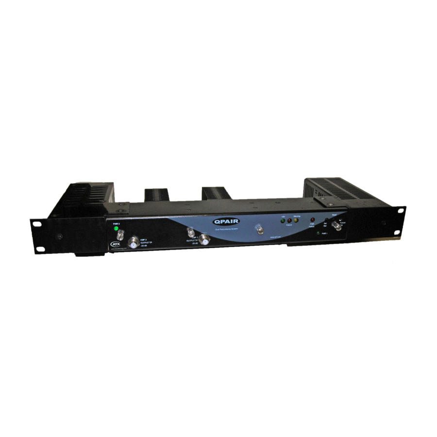
CHAPTER 1: DESCRIPTION OF INTERFACES DESCRIPTION OF INTERFACES Description of Interfaces QPAIR Redundant Amplifi er System Front View QPAIR Redundant Amplifi er System Rear View The QPAIR system (the system) has fi ve sections: two modular amplifi er sections, the RF switch section and two replaceable power supplies. - Page 6 CHAPTER 1: DESCRIPTION OF INTERFACES amplifier has its input at the right lower side of its amplifier board (see Figure 2). The signal flows up to the adjacent input pad, then left to the adjacent input equalizer, then back down to the hybrid module. From the output (left) side of the hybrid module, the signal flows up to the output pad socket, left to the adjacent output equalizer, through the output test point coupler and up to the output located at the upper left portion of the board.
- Page 7 CHAPTER 1: DESCRIPTION OF INTERFACES Alarms: Rear of Chassis: Form C contacts: C for common, NO for normally open, NC for normally closed. Description: A contact closure from the NO connection to the C connection is present when the unit is in operation and under power.
- Page 8 CHAPTER 1: DESCRIPTION OF INTERFACES This page left intentionally blank. Q-Series Amplifi ers – QPAIR Redundant Amplifi er System – Installation & Operation Manual ®...
-
Page 9: Description Of Operation
50 dBmV per channel. However, if only part of the TV channel spectrum is used, the maximum signal level per channel may be higher than 50 dBmV and the minimum signal level should be higher than 20 dBmV. If needed, contact ATX Networks for assistance in calculating the correct levels. - Page 10 CHAPTER 2: DESCRIPTION OF OPERATION This page left intentionally blank. Q-Series Amplifi ers – QPAIR Redundant Amplifi er System – Installation & Operation Manual ®...
-
Page 11: Set-Up Procedure
CHAPTER 3: SET-UP PROCEDURE SET-UP PROCEDURE Set-up Procedure Remove the front cover. See Appendix 1 for the proper method to remove the front cover. Connect main input cable to the RF INPUT on the left rear part of the chassis. Connect a cable from the TO AMP 1 port to RF IN of AMP 1 on the rear of the chassis. - Page 12 CHAPTER 3: SET-UP PROCEDURE APPENDIX APPENDIX 1: Method of Removing the Front Cover The front cover is held in place by captive thumbscrews. A partially threaded hollow tube guides the screws on the back of the cover. When removing, the screws need to be turned counterclockwise until they feel loose from the fastener located in the bottom of the amplifier/switch sections.
- Page 13 CHAPTER 3: SET-UP PROCEDURE 2 (secondary amplifier) on the back of the chassis and complete the troubleshooting methods as described above for AMP 1. APPENDIX 4: Removal/Replacement of Power Supply (See next page for Figures 3 & 4) If you need to remove and replace either of the power supplies, you will need to remove 5 screws and unplug 2 wires connecting the power supply to the chassis.
- Page 14 CHAPTER 3: SET-UP PROCEDURE Figure #5 - Sockets and Studs on Power Supply Connection QPAIR Redundant Amplifier System AMP 1 -20 dB OUTPUT T.P. AMP 1 IN AMP 1 OUT TO AMP 1 FROM AMP 1 DETECTOR RF SENSING DETECTOR SWITCH CONTROL RF INPUT...
-
Page 15: Specifications
Weight: 4.6 lbs (2.1 kg) Switch Specifications SPECIFICATIONS SWITCHING TIME 100ms default delay - contact ATX for different delay times ISOLATION 55 dB from 40-550 MHz; 50 dB from 550-1000 MHz INSERTION LOSS 2 dB (1 dB on the input and 1 dB on the output) - Page 16 CHAPTER 4: SPECIFICATIONS This page left intentionally blank. Q-Series Amplifi ers – QPAIR Redundant Amplifi er System – Installation & Operation Manual ®...
-
Page 17: Service & Support
Please contact ATX Technical Support for assistance with any ATX products. Please contact ATX Customer Service to obtain a valid RMA number for any ATX products that require service and are in or out-of-warranty before returning a failed module to the factory. - Page 18 9001:15 REGISTERED ATX Networks © 2018 ATX Networks 1-501 Clements Road West, Ajax, ON L1S 7H4 Canada Printed in Canada Information in this document is subject to change without notice. Tel: 905.428.6068 | Toll Free: 800.565.7488 | support@atxnetworks.com Rev. 07/18 (ANW0837)
Need help?
Do you have a question about the Q series and is the answer not in the manual?
Questions and answers