Table of Contents
Advertisement
Quick Links
Advertisement
Table of Contents

Related Manuals for TA T011S


Summary of Contents for TA T011S
-
Page 3: Table Of Contents
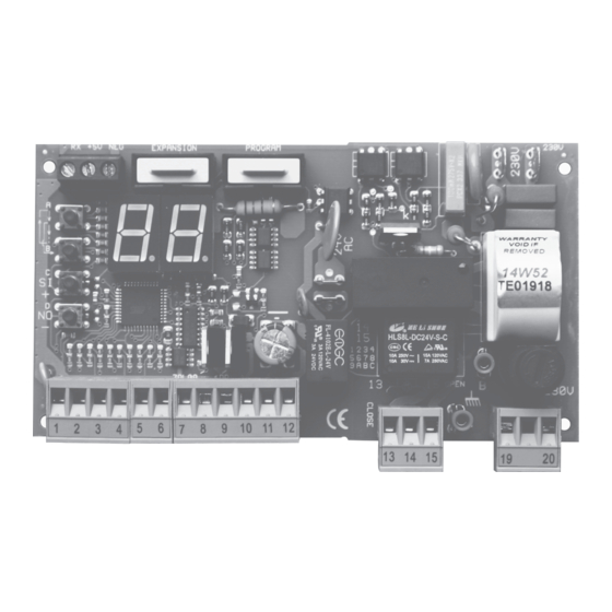
INDEX T011S ver. tS2111 ..................2 FUNCTIONS....................8 MENU NAVIGATION...................2 F0 AUTO-CLOSE TIME..............8 TROUBLE SHOOTING..................2 F1 PEDESTRIAN WORKING TIME..........8 -- NONE..................2 F2 CLOSING KICK................8 - REMOTE TRANSMITTING (REM)..........2 F3 BLINKING TIME................8 5t STOP (NC) (REM)..............2 F4 KICK BACK AT OPENING............8 tC EXTERNAL PHOTOCELL (NC)............2 F5 and F6 STANDARD, COMMUNITY MODE, STEP BY STEP ..8... - Page 4 T011S ver. tS2111 BOARD’S COMPONENTS Button A Button B Button C Button D 250 VAC power fuse 5A Resettable fuse 24V 1.6A Resettable fuse 24V 0.6A A B C Ground terminals Primary varistor Secondary varistor Terminal block pins 1 to 20 Button A...
-
Page 5: Menu Navigation
Terminal block input 3 is activated. Parameter E3 is set to tC EXTERNAL PHOTOCELL. EXT.PHOTOCELL (NC) Terminal block input 4 is activated. Parameter E4 is set to tA INTERNAL PHOTOCELL. INT.PHOTOCELL (NC) Terminal blocks inputs 3 and 4 are activated. Parameter E3 is set to tC EXTERNAL PHOTOCELL and INT. -
Page 6: Installing Radio Module
INSTALLING RADIO MODULE You can choose to install the radio module inside the flashing lamp or antenna to increase the signal range. FLASHING LAMP BASE RADIO-ANTENNA HOUSING Screws and stops not included. 3.5mm. x 13mm. COVER 3.5mm. x 13mm. LIGTHS 3.5 mm. -
Page 7: Connections
THE CONFIGURATIONS CANNOT BE USED AT THE SAME TIME SAME TIME EXTERNAL PHOTOCELLS N.C. tC INTERNAL PHOTOCELLS N.C. tA PHOTOCELLS TRANSMITTER DISABLED no DISABLED no EACH INPUTS CAN BE SET WITH DOMUS COMMAND: Eo → Normally Open or EC → Normally closed www.tecnoautomazione.com... -
Page 8: Glossary
When more inputs are activated at the same time the control board will show only the most critical input. The order from the most critical to the least critical input is: St = tC = tA = Go = PE = FC =... -
Page 9: Motor
MOTOR The opening and closing cycles are subdivided into two phases: The standard phase STANDARD A1 and the slowdown phase A2. WORKING TIME Programs the duration of the standard phase, during this time the force of the motor is A5. →... -
Page 10: Sensor Operating Mode
SENSOR OPERATING MODE There are two sensor operating modes: Obstacle Detection and Limit switch. They are described in the table below: OBSTACLE DETECTION LIMIT SWITCH In this operating mode the motor changes direction. If the direction was In this operating mode the motor finishes the closure, the gate opens completely. -
Page 11: Functions
FUNCTIONS The gate remains open for seconds at the end of opening before begging the closing phase. AUTO-CLOSE TIME To disable hold down @C button until display shows It is the motor working time during a pedestrian working cycle. The slowdown phase is skipped during the PEDESTRIAN WORKING TIME opening and executed during the closing. -
Page 12: F1 Pedestrian Working Time
FUNCTIONS L4 = SI → ENABLED L4 = no → DISABLED RECOVERY CYCLE This function can be enabled to open/close the gate in case of failure of one of the safety devices (photocells or stop). This function requires the installation of a start device (normally open contact) on the terminal block 1 or 7 and the setting of the parameter ( ) to one of the following functions: start,... -
Page 13: Remote
REMOTE Keep pressing A or B button until the display shows r0. After a few seconds the control SINGLE ERASE board starts scanning for stored codes. Each code showed is a remote key ID. To erase hold down button C. The display blinks showing remote key ID. When the display is off the remote key ID has been erased. -
Page 14: Terminal Block Inputs
INPUTS Each terminal block input has a control parameter. The control parameter sets the input function. The control parameters are: E1 → input 1, E2 → input 2 , E3 → input 3, E4 → input 4, E5 → input 5, E6 → input 6, and E7 → input 7. DEF. -
Page 15: Programming Procedure
PROGRAMMING PROCEDURE P1 is a semi-automatic procedure to acquire the working time parameters. The working MOTOR time parameters are A1, A2 and F0. In other words, after this procedure the standard WORKING TIME PROGRAMMING working time, the slowdown working time of the motor and the pause time are acquired by the control board. - Page 16 FORCE-OBSTACLE SENSOR CALIBRATION TABLES A5 and A6 The obstacle sensor stops or reverts the gate movement if an obstacle has been detected. The parameters set the A7 and A8 motor force and the sensor sensitivity. The parameters are the sensor calibration in standard and slowdown mode, respectively.
-
Page 17: Introduction Domus Module
INTRODUCTION DOMUS MODULE The DOMUS expansion consists of a DOMUS MODULE and up to three RELAY MODULES. The DOMUS module expands the control board with three open collector outputs. Each output controls a relay module. The DOMUS module has a push-button K1 to select the outputs menu and three LEDs: L1, L2 and L3. - Page 18 NOTES: www.tecnoautomazione.com Pag. 16 / 17...
Need help?
Do you have a question about the T011S and is the answer not in the manual?
Questions and answers