
Subscribe to Our Youtube Channel
Related Manuals for Endress+Hauser Proline Promass F 100


Summary of Contents for Endress+Hauser Proline Promass F 100
- Page 1 MANUAL Proline Promass F 100 Coriolis Flowmeter Modbus RS485 Operating Instructions Manual BA01659O/06/EN/02.17 Valid as of version 01.03 zz (Device firmware) 71382654...
- Page 2 • The manufacturer reserves the right to modify technical data without prior notice. Your Endress+Hauser Sales Center will supply you with current information and updates to these instructions. Important All information and technical specifications in this documentation have been carefully checked and compiled by the author.
-
Page 3: Table Of Contents
Proline Promass F 100 Modbus RS485 Table of contents Table of contents About this document ....6 Installation ..... . . 20 Document function . - Page 4 ......68 13.3 Endress+Hauser services ....89 10.7.1 Write protection via write protection...
- Page 5 Proline Promass F 100 Modbus RS485 Table of contents 16.4 Output ......
-
Page 6: About This Document
About this document Proline Promass F 100 Modbus RS485 About this document Document function These Operating Instructions contain all the information that is required in various phases of the life cycle of the device: from product identification, incoming acceptance and storage, to mounting, connection, operation and commissioning through to troubleshooting, maintenance and disposal. -
Page 7: Tool Symbols
Proline Promass F 100 Modbus RS485 About this document 1.2.3 Tool symbols Symbol Meaning Allen key Open-ended wrench 1.2.4 Symbols for certain types of information Symbol Meaning Permitted Procedures, processes or actions that are permitted. Preferred Procedures, processes or actions that are preferred. -
Page 8: Documentation
• The W@M Device Viewer : Enter the serial number from the nameplate (www.endress.com/deviceviewer) • The Endress+Hauser Operations App: Enter the serial number from the nameplate or scan the 2-D matrix code (QR code) on the nameplate. For a detailed list of the individual documents along with the documentation code →... - Page 9 Proline Promass F 100 Modbus RS485 About this document Microsoft® Registered trademark of the Microsoft Corporation, Redmond, Washington, USA TRI-CLAMP® Registered trademark of Ladish & Co., Inc., Kenosha, USA...
-
Page 10: Basic Safety Instructions
Basic safety instructions Proline Promass F 100 Modbus RS485 Basic safety instructions Requirements for the personnel The personnel for installation, commissioning, diagnostics and maintenance must fulfill the following requirements: ‣ Trained, qualified specialists must have a relevant qualification for this specific function and task. -
Page 11: Workplace Safety
Verification for borderline cases: ‣ For special fluids and fluids for cleaning, Endress+Hauser is glad to provide assistance in verifying the corrosion resistance of fluid-wetted materials, but does not accept any warranty or liability as minute changes in the temperature, concentration or level of contamination in the process can alter the corrosion resistance properties. -
Page 12: Product Safety
It meets general safety standards and legal requirements. It also complies with the EU directives listed in the device-specific EU Declaration of Conformity. Endress+Hauser confirms this by affixing the CE mark to the device. -
Page 13: Product Description
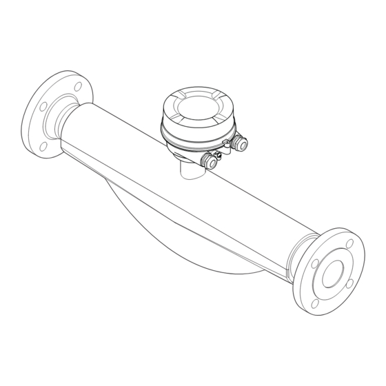
Proline Promass F 100 Modbus RS485 Product description Product description The device consists of a transmitter and a sensor. The Safety Barrier Promass 100 is part of the scope of supply and must be implemented to operate the device. The device is available as a compact version: The transmitter and sensor form a mechanical unit. -
Page 14: Identification
A0028673 and documents present? • If one of the conditions is not satisfied, contact your Endress+Hauser Sales Center. • Depending on the device version, the CD-ROM might not be part of the delivery! The Technical Documentation is available via the Internet or via the Endress+Hauser... -
Page 15: Product Identification
• Enter the serial number from the nameplates into the Endress+Hauser Operations App or scan the 2-D matrix code (QR code) on the nameplate with the Endress+Hauser Operations App: all the information for the measuring device is displayed. For an overview of the scope of the associated Technical Documentation, refer to the following: •... -
Page 16: Sensor Nameplate
Incoming acceptance and product identification Proline Promass F 100 Modbus RS485 4.2.2 Sensor nameplate Order code: Ser. no.: Ext. ord. cd.: Date: A0029199 3 Example of a sensor nameplate Name of the sensor Manufacturing location Order code Serial number (ser. no.) Extended order code (Ext. -
Page 17: Symbols On Measuring Device
Proline Promass F 100 Modbus RS485 Incoming acceptance and product identification 4.2.3 Promass 100 safety barrier nameplate Safe area NON intrinsically safe circuit (grey terminals) Promass 100 Safety Barrier Intrinsically safe circuits (blue terminals) HAZARDOUS area A0017854 4 Example of a Promass 100 safety barrier nameplate Non-hazardous area or Zone 2/Div. -
Page 18: Storage And Transport
Storage and transport Proline Promass F 100 Modbus RS485 Storage and transport Storage conditions Observe the following notes for storage: ‣ Store in the original packaging to ensure protection from shock. ‣ Do not remove protective covers or protective caps installed on process connections. -
Page 19: Measuring Devices With Lifting Lugs
Proline Promass F 100 Modbus RS485 Storage and transport A0029214 5.2.2 Measuring devices with lifting lugs CAUTION Special transportation instructions for devices with lifting lugs ‣ Only use the lifting lugs fitted on the device or flanges to transport the device. -
Page 20: Installation
Installation Proline Promass F 100 Modbus RS485 Installation Installation conditions No special measures such as supports are necessary. External forces are absorbed by the construction of the device. 6.1.1 Mounting position Mounting location A0028772 To prevent measuring errors arising from accumulation of gas bubbles in the measuring tube, avoid the following mounting locations in the pipe: •... - Page 21 Proline Promass F 100 Modbus RS485 Installation A0028773 5 Installation in a down pipe (e.g. for batching applications) Supply tank Sensor Orifice plate, pipe restriction Valve Batching tank Ø orifice plate, pipe restriction [mm] [in] [mm] [in] ³⁄₈ 0.24 ½...
- Page 22 Installation Proline Promass F 100 Modbus RS485 Orientation Recommendation Horizontal orientation, transmitter at bottom Exceptions: → 6, 22 A0015590 Horizontal orientation, transmitter at side A0015592 Applications with low process temperatures may decrease the ambient temperature. To maintain the minimum ambient temperature for the transmitter, this orientation is recommended.
-
Page 23: Process
Proline Promass F 100 Modbus RS485 Installation 6.1.2 Requirements from environment and process Ambient temperature range Measuring device • –40 to +60 °C (–40 to +140 °F) • Order code for "Test, certificate", option JM: –50 to +60 °C (–58 to +140 °F) Safety Barrier Promass 100 –40 to +60 °C (–40 to +140 °F) - Page 24 Installation Proline Promass F 100 Modbus RS485 NOTICE Electronics overheating on account of thermal insulation! ‣ Recommended orientation: horizontal orientation, transmitter housing pointing downwards. ‣ Do not insulate the transmitter housing . ‣ Maximum permissible temperature at the lower end of the transmitter housing: 80 °C (176 °F)
-
Page 25: Special Mounting Instructions
Proline Promass F 100 Modbus RS485 Installation The sheet must have the following properties: • Relative magnetic permeability µr ≥ 300 • Plate thickness d ≥ 0.35 mm (d ≥ 0.014 in) Vibrations The high oscillation frequency of the measuring tubes ensures that the correct operation of the measuring system is not influenced by plant vibrations. -
Page 26: Mounting The Measuring Device
Installation Proline Promass F 100 Modbus RS485 DN 8 ( ")...150 (6") DN 250 (10") ⁄ RUPTURE DISK A0028903 Rupture disk label Rupture disk with 1/2" NPT internal thread with 1" width across flat Transport protection Zero point adjustment All measuring devices are calibrated in accordance with state-of-the-art technology. -
Page 27: Mounting The Measuring Device
Proline Promass F 100 Modbus RS485 Installation 6.2.3 Mounting the measuring device WARNING Danger due to improper process sealing! ‣ Ensure that the inside diameters of the gaskets are greater than or equal to that of the process connections and piping. -
Page 28: Electrical Connection
Electrical connection Proline Promass F 100 Modbus RS485 Electrical connection NOTICE The measuring device does not have an internal circuit breaker. ‣ For this reason, assign the measuring device a switch or power-circuit breaker so that the power supply line can be easily disconnected from the mains. -
Page 29: Terminal Assignment
Proline Promass F 100 Modbus RS485 Electrical connection Signal damping Max. 9 dB over the entire length of the cable cross-section Shield Copper braided shielding or braided shielding with foil shield. When grounding the cable shield, observe the grounding concept of the plant. - Page 30 Electrical connection Proline Promass F 100 Modbus RS485 Depending on the housing version, the transmitters can be ordered with terminals or device plugs. Connection methods available Order code Possible options for order code Power "Housing" "Electrical connection" Output supply Options...
- Page 31 Proline Promass F 100 Modbus RS485 Electrical connection Depending on the housing version, the transmitters can be ordered with terminals or device plugs. Connection methods available Order code Possible options for order code Power "Housing" "Electrical connection" Output supply Options...
-
Page 32: Pin Assignment, Device Plug
Electrical connection Proline Promass F 100 Modbus RS485 Safety Barrier Promass 100 Power Modbus supply RS485 Safe area Power Lift panel for bus termination Communication Safety Barrier Promass 100 Hazardous area Power Modbus supply RS485 A0030220 10 Safety Barrier Promass 100 with terminals... -
Page 33: Shielding And Grounding
Proline Promass F 100 Modbus RS485 Electrical connection Grounding/shielding Coding Plug/socket Plug Signal transmission Promass Device plug for signal transmission (device side), MODBUS RS485 (not intrinsically safe) For use in the non-hazardous area and Zone 2/Div. 2. Assignment Not assigned... -
Page 34: Preparing The Measuring Device
Electrical connection Proline Promass F 100 Modbus RS485 7.1.6 Preparing the measuring device NOTICE Insufficient sealing of the housing! Operational reliability of the measuring device could be compromised. ‣ Use suitable cable glands corresponding to the degree of protection. 1. Remove dummy plug if present. -
Page 35: Promass 100
Proline Promass F 100 Modbus RS485 Electrical connection 8 mm 8 mm 3 mm 10 (0.4) mm (in) A0017844 12 Device versions with connection examples Cable Device plug for signal transmission Device plug for supply voltage ‣ Connect the cable in accordance with the terminal assignment or the device plug pin assignment . -
Page 36: Ensure Potential Equalization
Electrical connection Proline Promass F 100 Modbus RS485 L- L+ A0028766 13 Electrical connection between the transmitter and Safety Barrier Promass 100 Control system (e.g. PLC) Observe cable specifications → 28 Safety Barrier Promass 100: terminal assignment → 32 Observe cable specifications →... -
Page 37: Special Connection Instructions
Proline Promass F 100 Modbus RS485 Electrical connection Special connection instructions 7.3.1 Connection examples Modbus RS485 Modbus RS485, non-hazardous area and Zone 2/Div. 2 A0028765 14 Connection example for Modbus RS485, non-hazardous area and Zone 2/Div. 2 Control system (e.g. PLC) Cable shield: the cable shield must be grounded at both ends to comply with EMC requirements;... -
Page 38: Ensuring The Degree Of Protection
Electrical connection Proline Promass F 100 Modbus RS485 Ensuring the degree of protection The measuring device fulfills all the requirements for the IP66/67 degree of protection, Type 4X enclosure. To guarantee IP66/67 degree of protection, Type 4X enclosure, carry out the following steps after the electrical connection: 1. -
Page 39: Operation Options
Proline Promass F 100 Modbus RS485 Operation options Operation options Overview of operating options A0017760 Computer with "FieldCare" or "DeviceCare" operating tool via Commubox FXA291 and service interface Control system (e.g. PLC) -
Page 40: Menu
Operation options Proline Promass F 100 Modbus RS485 Structure and function of the operating menu 8.2.1 Structure of the operating menu For an overview of the operating menu for experts: "Description of Device Parameters" document supplied with the device→ 116... - Page 41 Proline Promass F 100 Modbus RS485 Operation options Operating menu for operators and maintenances Language Operatation Language Parameter 1 Parameter n Submenu 1 Submenu n Setup Device tag Wizard 1 / Parameter 1 Wizard n / Parameter n Advanced setup...
-
Page 42: Operating Philosophy
Operation options Proline Promass F 100 Modbus RS485 8.2.2 Operating philosophy The individual parts of the operating menu are assigned to certain user roles (operator, maintenance etc.). Each user role contains typical tasks within the device lifecycle. Menu/parameter User role and tasks... -
Page 43: Access To The Operating Menu Via The Operating Tool
Computer with "FieldCare" operating tool with COM DTM "CDI Communication FXA291" Via service interface (CDI) A0014019 Service interface (CDI = Endress+Hauser Common Data Interface) of the measuring device Commubox FXA291 Computer with FieldCare operating tool with COM DTM CDI Communication FXA291... -
Page 44: Fieldcare
FieldCare Function scope FDT-based plant asset management tool from Endress+Hauser. It can configure all smart field devices in a system and helps you manage them. By using the status information, it is also a simple but effective way of checking their status and condition. -
Page 45: Devicecare
DeviceCare Function scope Tool to connect and configure Endress+Hauser field devices. The fastest way to configure Endress+Hauser field devices is with the dedicated "DeviceCare" tool. Together with the device type managers (DTMs) it presents a convenient, comprehensive solution. For details, see Innovation Brochure IN01047S Source for device description files See information →... -
Page 46: System Integration
System integration Proline Promass F 100 Modbus RS485 System integration Overview of device description files 9.1.1 Current version data for the device Firmware version 01.03.zz • On the title page of the Operating Instructions • On the transmitter nameplate • Firmware version Diagnostics →... - Page 47 Proline Promass F 100 Modbus RS485 System integration Code Name Description Application Read holding Master reads one or more Modbus Read device parameters with read register registers from the device. and write access A maximum of 125 consecutive Example: registers can be read with 1...
-
Page 48: Register Information
System integration Proline Promass F 100 Modbus RS485 9.2.2 Register information For an overview of device parameters with their respective Modbus register information, please refer to the "Modbus RS485 register information" section in the "Description of device parameters" documentation . - Page 49 Proline Promass F 100 Modbus RS485 System integration 3 – 2 – 1 – 0 Byte 3 Byte 2 Byte 1 Byte 0 (SEEEEEEE) (EMMMMMMM) (MMMMMMMM) (MMMMMMMM) * = factory setting, S = sign, E = exponent, M = mantissa...
- Page 50 System integration Proline Promass F 100 Modbus RS485 Scan list configuration For configuration, the Modbus RS485 register addresses of the device parameters to be grouped must be entered in the scan list. Please note the following basic requirements of the scan list: Max.
- Page 51 Proline Promass F 100 Modbus RS485 System integration Data area Device parameter value Modbus RS485 register Data type* Access** Start register End register (Float only) Value of scan list register ... Value of scan list register 15 5081 5082 Integer/float Read/write * Data type depends on the device parameters entered in the scan list.
- Page 52 Commissioning Proline Promass F 100 Modbus RS485 Commissioning 10.1 Function check Before commissioning the measuring device: ‣ Make sure that the post-installation and post-connection checks have been performed. • "Post-installation check" checklist→ 27 • "Post-connection check" checklist → 38 10.2...
-
Page 53: Defining The Tag Name
Proline Promass F 100 Modbus RS485 Commissioning 10.4.1 Defining the tag name To enable fast identification of the measuring point within the system, you can enter a unique designation using the Device tag parameter and thus change the factory setting. - Page 54 Commissioning Proline Promass F 100 Modbus RS485 Parameter overview with brief description Parameter Description Selection Factory setting Mass flow unit Select mass flow unit. Unit choose list Country-specific: • kg/h Result • lb/min The selected unit applies for: • Output •...
- Page 55 Proline Promass F 100 Modbus RS485 Commissioning Parameter Description Selection Factory setting Temperature unit Select temperature unit. Unit choose list Country-specific: • °C Result • °F The selected unit applies for: • Electronic temperature parameter (6053) • Maximum value parameter (6051) •...
- Page 56 Commissioning Proline Promass F 100 Modbus RS485 10.4.3 Selecting and setting the medium The Select medium wizard submenu contains parameters that must be configured in order to select and set the medium. Navigation "Setup" menu → Medium selection ‣ Medium selection Select medium →...
-
Page 57: Interface
Proline Promass F 100 Modbus RS485 Commissioning Parameter overview with brief description Parameter Prerequisite Description Selection / User Factory setting entry Select medium – Select medium type. • Liquid Liquid • Gas Select gas type The Gas option is selected in Select measured gas type. - Page 58 Commissioning Proline Promass F 100 Modbus RS485 Navigation "Setup" menu → Communication ‣ Communication Bus address → 58 → 58 Baudrate Data transfer mode → 58 Parity → 58 Byte order → 58 Failure mode →...
- Page 59 Proline Promass F 100 Modbus RS485 Commissioning Parameter Description User entry / Selection Factory setting Assign diagnostic behavior Select diagnostic behavior for MODBUS • Off Alarm communication. • Alarm or warning • Warning • Alarm Failure mode Select measured value output behavior when •...
- Page 60 Commissioning Proline Promass F 100 Modbus RS485 10.4.5 Configuring the low flow cut off The Low flow cut off submenu contains the parameters that must be set in order to configure the low flow cut off. Navigation "Setup" menu → Low flow cut off ‣...
- Page 61 Proline Promass F 100 Modbus RS485 Commissioning 10.4.6 Configuring the partial filled pipe detection The Partially filled pipe detection submenu contains parameters that have to be set for configuring empty pipe detection. Navigation "Setup" menu → Partially filled pipe detection ‣...
-
Page 62: Enter Access Code
Commissioning Proline Promass F 100 Modbus RS485 10.5 Advanced settings The Advanced setup submenu together with its submenus contains parameters for specific settings. The number of submenus can vary depending on the device version, e.g. viscosity is available only with the Promass I. - Page 63 Proline Promass F 100 Modbus RS485 Commissioning Navigation "Setup" menu → Advanced setup → Calculated values ‣ Calculated values ‣ Corrected volume flow calculation → 63 Corrected volume flow calculation External reference density → 63 Fixed reference density →...
-
Page 64: Sensor Adjustment
Commissioning Proline Promass F 100 Modbus RS485 Parameter Prerequisite Description Selection / User Factory setting interface / User entry Linear expansion coefficient The Calculated reference Enter linear, medium-specific Signed floating-point density option is selected in expansion coefficient for number the Corrected volume flow calculating the reference calculation parameter density. -
Page 65: Totalizer 1 To N
Proline Promass F 100 Modbus RS485 Commissioning Navigation "Setup" menu → Advanced setup → Sensor adjustment → Zero point adjustment ‣ Zero point adjustment Zero point adjustment control → 65 → 65 Progress Parameter overview with brief description... -
Page 66: Administration
Commissioning Proline Promass F 100 Modbus RS485 Parameter overview with brief description Parameter Prerequisite Description Selection Factory setting Assign process variable – Select process variable for • Off Mass flow totalizer. • Mass flow • Volume flow • Corrected volume flow •... - Page 67 Proline Promass F 100 Modbus RS485 Commissioning Parameter overview with brief description Parameter Description Selection Factory setting Device reset Reset the device configuration - either • Cancel Cancel entirely or in part - to a defined state. • To delivery settings •...
- Page 68 Commissioning Proline Promass F 100 Modbus RS485 Parameter overview with brief description Parameter Prerequisite Description Selection / User Factory setting entry Assign simulation process variable – Select a process variable for • Off the simulation process that is • Mass flow activated.
- Page 69 Proline Promass F 100 Modbus RS485 Commissioning A0030224 Setting the write protection switch on the main electronics module to the On position enables hardware write protection. Setting the write protection switch on the main electronics module to the Off position (factory setting) disables hardware write protection.
- Page 70 Operation Proline Promass F 100 Modbus RS485 Operation 11.1 Reading the device locking status Device active write protection: Locking status parameter Navigation "Operation" menu → Locking status Function scope of "Locking status" parameter Options Description Hardware locked The locking switch (DIP switch) for locking the hardware is activated on the main electronic module.
- Page 71 Proline Promass F 100 Modbus RS485 Operation Navigation "Diagnostics" menu → Measured values → Measured variables ‣ Measured variables Mass flow → 71 → 71 Volume flow Corrected volume flow → 71 Density → 71 Reference density →...
- Page 72 Operation Proline Promass F 100 Modbus RS485 Parameter Prerequisite Description User interface Reference density – Displays the reference density currently Signed floating-point calculated. number Dependency The unit is taken from the Reference density unit parameter (→ 54). Temperature –...
-
Page 73: Performing A Totalizer Reset
Proline Promass F 100 Modbus RS485 Operation Navigation "Diagnostics" menu → Measured values → Totalizer ‣ Totalizer Totalizer value 1 to n → 73 → 73 Totalizer overflow 1 to n Parameter overview with brief description Parameter Prerequisite... - Page 74 Operation Proline Promass F 100 Modbus RS485 Navigation "Operation" menu → Totalizer handling ‣ Totalizer handling Control Totalizer 1 to n → 74 → 74 Preset value 1 to n Reset all totalizers → 74 Parameter overview with brief description...
-
Page 75: Totalizer" Parameter
Proline Promass F 100 Modbus RS485 Operation 11.5.1 Function scope of the "Control Totalizer" parameter Options Description Totalize The totalizer is started or continues running. Reset + hold The totaling process is stopped and the totalizer is reset to 0. -
Page 76: General Troubleshooting
Diagnostics and troubleshooting Proline Promass F 100 Modbus RS485 Diagnostics and troubleshooting 12.1 General troubleshooting For output signals Error Possible causes Solution Green power LED on the main Supply voltage does not match the Apply the correct supply voltage . -
Page 77: Diodes
Proline Promass F 100 Modbus RS485 Diagnostics and troubleshooting Error Possible causes Solution Operation with FieldCare or Firewall of computer or network is Depending on the settings of the DeviceCare via CDI-RJ45 service preventing communication firewall used on the computer or in... - Page 78 Diagnostics and troubleshooting Proline Promass F 100 Modbus RS485 Xxxxxx/…/…/ Device name: Xxxxxxx kg/h Mass flow: 12.34 Device tag: Xxxxxxx Volume flow: 12.34 ³ m /h Status signal: Function check (C) Xxxxxx Diagnostics 1: C485 Simu... Remedy information: Deactivate... Failure (F)
- Page 79 Proline Promass F 100 Modbus RS485 Diagnostics and troubleshooting Diagnostic information Diagnostic code Status signal Diagnostic number Short text ↓ ↓ ↓ Example Process limit A0013958 3-digit number 12.3.2 Calling up remedy information Remedy information is provided for every diagnostic event to ensure that problems can be rectified quickly: •...
- Page 80 Diagnostics and troubleshooting Proline Promass F 100 Modbus RS485 Parameter overview with brief description Parameters Description Selection Factory setting Failure mode Select measured value • NaN value NaN value output behavior when a • Last valid value diagnostic message occurs ...
- Page 81 Proline Promass F 100 Modbus RS485 Diagnostics and troubleshooting Diagnostic Short text Remedy instructions Status Diagnostic number signal behavior [from the [from the factory] factory] Sensor limit exceeded 1. Inspect sensor Alarm 2. Check process condition Sensor connection 1. Change main electronic...
- Page 82 Diagnostics and troubleshooting Proline Promass F 100 Modbus RS485 Diagnostic Short text Remedy instructions Status Diagnostic number signal behavior [from the [from the factory] factory] Simulation measured Deactivate simulation Warning variable Special event 3 Contact service Alarm Special event 7...
- Page 83 Proline Promass F 100 Modbus RS485 Diagnostics and troubleshooting 12.7 Pending diagnostic events The Diagnostics menu allows the user to view the current diagnostic event and the previous diagnostic event separately. To call up the measures to rectify a diagnostic event: •...
- Page 84 Diagnostics and troubleshooting Proline Promass F 100 Modbus RS485 Navigation path Diagnostics → Diagnostic list To call up the measures to rectify a diagnostic event: • Via "FieldCare" operating tool → 79 • Via "DeviceCare" operating tool → 79 12.9...
- Page 85 Proline Promass F 100 Modbus RS485 Diagnostics and troubleshooting 12.9.3 Overview of information events Unlike a diagnostic event, an information event is displayed in the event logbook only and not in the diagnostic list. Info number Info name I1000 --------(Device ok)
- Page 86 Diagnostics and troubleshooting Proline Promass F 100 Modbus RS485 Options Description To delivery settings Every parameter for which a customer-specific default setting was ordered is reset to this customer-specific value. All other parameters are reset to the factory setting. ...
- Page 87 Proline Promass F 100 Modbus RS485 Diagnostics and troubleshooting Parameter Description User interface Factory setting Firmware version Shows the device firmware version installed. Character string in the format – xx.yy.zz Device name Shows the name of the transmitter. Max. 32 characters such as Promass 100 letters or numbers.
- Page 88 "Manufacturer' s information" document. The manufacturer' s information is available: • In the Download Area of the Endress+Hauser web site: www.endress.com → Downloads • Specify the following details: –...
- Page 89 → 106. 13.2 Measuring and test equipment Endress+Hauser offers a wide variety of measuring and test equipment, such as W@M or device tests. Your Endress+Hauser Sales Center can provide detailed information on the services. List of some of the measuring and testing equipment: → 92 13.3...
- Page 90 • The measuring devices have a modular design. • Spare parts are grouped into logical kits with the associated Installation Instructions. • Repairs are carried out by Endress+Hauser Service or by appropriately trained customers. • Certified devices can only be converted to other certified devices by Endress+Hauser Service or at the factory.
- Page 91 Proline Promass F 100 Modbus RS485 Repairs 14.5 Disposal 14.5.1 Removing the measuring device 1. Switch off the device. WARNING Danger to persons from process conditions. ‣ Beware of hazardous process conditions such as pressure in the measuring device, high temperatures or aggressive fluids.
- Page 92 Various accessories, which can be ordered with the device or subsequently from Endress +Hauser, are available for the device. Detailed information on the order code in question is available from your local Endress+Hauser sales center or on the product page of the Endress+Hauser website: www.endress.com.
- Page 93 Tool for connecting and configuring Endress+Hauser field devices. For details, see Innovation brochure IN01047S Commubox FXA291 Connects Endress+Hauser field devices with a CDI interface (= Endress+Hauser Common Data Interface) and the USB port of a computer or laptop. For details, see "Technical Information" TI00405C 15.4...
- Page 94 Technical data Proline Promass F 100 Modbus RS485 Technical data 16.1 Application The measuring device is suitable for flow measurement of liquids and gases only. Depending on the version ordered, the measuring device can also measure potentially explosive, flammable, poisonous and oxidizing media.
-
Page 95: Input
Proline Promass F 100 Modbus RS485 Technical data 16.3 Input Measured variable Direct measured variables • Mass flow • Density • Temperature Calculated measured variables • Volume flow • Corrected volume flow • Reference density Measuring range Measuring ranges for liquids Measuring range full scale values ... -
Page 96: Output
Technical data Proline Promass F 100 Modbus RS485 [mm] [in] [kg/m 1½ Calculation example for gas • Sensor: Promass F, DN 50 • Gas: Air with a density of 60.3 kg/m³ (at 20 °C and 50 bar) • Measuring range (liquid): 70 000 kg/h •... - Page 97 Proline Promass F 100 Modbus RS485 Technical data Current output 4 to 20 mA 4 to 20 mA Failure mode Choose from: • 4 to 20 mA in accordance with NAMUR recommendation NE 43 • 4 to 20 mA in accordance with US •...
-
Page 98: Power Supply
Technical data Proline Promass F 100 Modbus RS485 Low flow cut off The switch points for low flow cut off are user-selectable. Galvanic isolation The following connections are galvanically isolated from each other: • Outputs • Power supply Protocol-specific data Protocol Modbus Applications Protocol Specification V1.1... - Page 99 Proline Promass F 100 Modbus RS485 Technical data Promass 100 safety barrier DC 20 to 30 V Power consumption Transmitter Maximum Order code for "Output" Power consumption Option M Modbus RS485, for use in non-hazardous areas and Zone 2/ 3.5 W Div.
-
Page 100: Performance Characteristics
Technical data Proline Promass F 100 Modbus RS485 Cable entries • Cable gland: M20 × 1.5 with cable 6 to 12 mm (0.24 to 0.47 in) • Thread for cable entry: – M20 – G ½" – NPT ½" Cable specification →... - Page 101 Proline Promass F 100 Modbus RS485 Technical data Zero point stability Zero point stability [mm] [in] [kg/h] [lb/min] ³⁄₈ 0.030 0.001 ½ 0.200 0.007 0.540 0.019 1½ 2.25 0.083 3.50 0.129 0.330 14.0 0.514 32.0 1.17 88.0 3.23 Flow values Flow values as turndown parameter depending on nominal diameter.
- Page 102 Technical data Proline Promass F 100 Modbus RS485 1:10 1:20 1:50 1:100 1:500 [inch] [lb/min] [lb/min] [lb/min] [lb/min] [lb/min] [lb/min] 29 400 2 940 1 470 58.80 80 850 8 085 4 043 1 617 808.5 161.7 Accuracy of outputs The output accuracy must be factored into the measured error if analog outputs are used, but can be ignored for fieldbus outputs (e.g.
- Page 103 Proline Promass F 100 Modbus RS485 Technical data The effect is reduced if zero point adjustment is performed at process temperature. Density When there is a difference between the density calibration temperature and the process temperature, the typical measured error of the sensor is ±0.00005 g/cm...
- Page 104 Technical data Proline Promass F 100 Modbus RS485 [% o.r./bar] [% o.r./psi] [mm] [in] –0.008 –0.0006 –0.009 –0.0006 –0.007 –0.0005 –0.009 –0.0006 –0.009 –0.0006 Design fundamentals o.r. = of reading, o.f.s. = of full scale value BaseAccu = base accuracy in % o.r., BaseRepeat = base repeatability in % o.r.
-
Page 105: Installation
Proline Promass F 100 Modbus RS485 Technical data 16.7 Installation "Mounting requirements" → 20 16.8 Environment Ambient temperature → 23 range Temperature tables Observe the interdependencies between the permitted ambient and fluid temperatures when operating the device in hazardous areas. -
Page 106: Process
Technical data Proline Promass F 100 Modbus RS485 16.9 Process Medium temperature range Standard version –50 to +150 °C (–58 to +302 °F) Order code for "Measuring tube mat., wetted surface", option HA, SA, SB, SC Extended temperature version –50 to +240 °C (–58 to +464 °F) Order code for "Measuring tube... - Page 107 Proline Promass F 100 Modbus RS485 Technical data Pressure-temperature An overview of the pressure-temperature ratings for the process connections is ratings provided in the "Technical Information" document Secondary containment For the Standard version with the temperature range –50 to +150 °C (–58 to +302 °F), the sensor housing is filled with dry nitrogen gas and protects the electronics and mechanics inside.
- Page 108 Technical data Proline Promass F 100 Modbus RS485 In case of a tube failure, the pressure level inside the secondary containment will rise according to the operating process pressure. If the user judges that the secondary containment pressure rating/burst pressure does not provide an adequate safety margin, the device can be fitted with a rupture disk.
-
Page 109: Mechanical Construction
Proline Promass F 100 Modbus RS485 Technical data 16.10 Mechanical construction Design, dimensions For the dimensions and installation lengths of the device, see the "Technical Information" document, "Mechanical construction" section. Weight All values (weight exclusive of packaging material) refer to devices with EN/DIN PN 40 flanges. - Page 110 Technical data Proline Promass F 100 Modbus RS485 Materials Transmitter housing • Order code for "Housing", option A "Compact, aluminum coated": Aluminum, AlSi10Mg, coated • Order code for "Housing", option B "Compact, hygienic, stainless": – Hygienic version, stainless steel 1.4301 (304) –...
- Page 111 Proline Promass F 100 Modbus RS485 Technical data Device plug Electrical connection Material Plug M12x1 • Socket: Stainless steel, 1.4404 (316L) • Contact housing: Polyamide • Contacts: Gold-plated brass Sensor housing • Acid and alkali-resistant outer surface • DN 08 to DN 150: stainless steel, 1.4301 (304) Optional: order code for "Sensor option", option CC: stainless steel, 1.4404 (316L)
-
Page 112: Operability
Technical data Proline Promass F 100 Modbus RS485 Process connections • Fixed flange connections: – EN 1092-1 (DIN 2501) flange – EN 1092-1 (DIN 2512N) flange – Namur lengths in accordance with NE 132 – ASME B16.5 flange – JIS B2220 flange –... -
Page 113: Certificates And Approvals
EU Directives. These are listed in the corresponding EU Declaration of Conformity along with the standards applied. Endress+Hauser confirms successful testing of the device by affixing to it the CE mark. C-Tick symbol The measuring system meets the EMC requirements of the "Australian Communications and Media Authority (ACMA)". -
Page 114: Application Packages
The application packages can be ordered with the device or subsequently from Endress+Hauser. Detailed information on the order code in question is available from your local Endress+Hauser sales center or on the product page of the Endress+Hauser website: www.endress.com. -
Page 115: Accessories
For an overview of the scope of the associated Technical Documentation, refer to the following: • The W@M Device Viewer : Enter the serial number from the nameplate (www.endress.com/deviceviewer) • The Endress+Hauser Operations App: Enter the serial number from the nameplate or scan the 2-D matrix code (QR code) on the nameplate. - Page 116 Technical data Proline Promass F 100 Modbus RS485 Standard documentation Brief Operating Instructions Brief Operating Instructions for the sensor Measuring device Documentation code Proline Promass F KA01357O Transmitter Brief Operating Instructions Measuring device Documentation code Proline Promass 100 KA01335D Technical Information...
- Page 117 Proline Promass F 100 Modbus RS485 Technical data Installation Instructions Contents Comment Installation instructions for spare part sets and accessories • Access the overview of all the available spare part sets via W@M Device Viewer → 90 • Accessories available for order with Installation Instructions → 92...
-
Page 118: Index
Index Proline Promass F 100 Modbus RS485 Index 0 … 9 Design fundamentals Maximum measured error ....104 3-A approval ......113 Repeatability . - Page 119 Proline Promass F 100 Modbus RS485 Index Environment Inspection Impact resistance ......105 Received goods ......14 Shock resistance .
- Page 120 Index Proline Promass F 100 Modbus RS485 Menu Device information (Submenu) ....86 Diagnostics ......83 Diagnostics (Menu) .
- Page 121 Proline Promass F 100 Modbus RS485 Index Sensor System design Mounting ....... 27 Measuring system .
- Page 122 The specifications contained herein are subject to change without notice and any user of said specifications should verify from the manufacturer that the specifications are currently in ef- fect. Otherwise, the manufacturer assumes no responsibility for the use of specifications which may have been changed and are no longer in effect. Contact information is subject to change.
Need help?
Do you have a question about the Proline Promass F 100 and is the answer not in the manual?
Questions and answers