
Related Manuals for Gehl RS6-34


Summary of Contents for Gehl RS6-34
- Page 1 Form No. 913323 Revision C January RS6-34 2012 Telescopic Handler Serial Number 21541 thru 21700 (with Tier 3 engine) Beginning with Serial Number 21701 (with Interim Tier 4 engine)
- Page 2 Indicator and Operation Symbols Read Operator’s Fasten Seat Belt Parking Brake Brake Failure Safety Alert Hazard Flasher Manual Ignition Off Ignition ON Engine Start Engine Oil Engine Oil Engine Coolant Pressure Temperature Starting Aid Volume Full Volume Half Full Volume Empty Fuel Diesel Fuel Injection...
-
Page 3: Table Of Contents
Warranty ........Inside Back Cover IDENTIFICATION INFORMATION Write your Gehl Telescopic Handler serial number below. Refer to the model and serial number when inquiring about parts or service from your Gehl dealer. MODEL NO. RS6-34 SERIAL NO. -
Page 4: Introduction
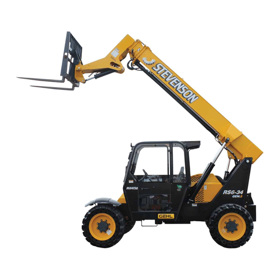
A storage pocket in the back of the seat is provided for storing the Operator’s Manual. After using the manual, please return it to the pocket and keep it with the unit at all times! If this machine is resold, Gehl Company rec- ommends that this manual be given to the new owner. - Page 5 Identification Boom Angle Dash Indicators Telescopic Boom Indicator and Controls Quick-attach System Slave Cylinder Tilt Cylinder Seat Operator’s Station Lift Cylinder Extend Cylinder Rear Boom Access Cover Auxiliary Hydraulics Exhaust Pipe (not shown) Access Cover with Rear Lights and Backup Alarm Frame Leveling Air Cleaner Hydraulic...
-
Page 6: Specifications
Chapter 2 SPECIFICATIONS Lifting Performance Steering System Axles (front and rear) Steer Valve: Fixed displacement rotary Maximum lift capacity: Type: Dana Displacement/Rev: 17.9 cu. in. (293 cc) 6000 lbs. (2721 kg) Drive/steer, open differential, double System pressure: 2000 psi (138 bar) reduction planetary, full-time four- Maximum lift height: Steer cylinders: 1 per axle... -
Page 7: Check Lists
Chapter 3 CHECKLISTS PRE-DELIVERY I acknowledge that the pre-delivery procedures were per- formed on this unit as outlined above. The following Checklist is an important reminder of the inspections that MUST be made before delivering the Telescopic Handler to the customer. Check off each item Dealership’s Name after the prescribed action is taken. - Page 8 INTENTIONALLY BLANK (To be removed as Dealer’s file copy) 913323/CP0112 PRINTED IN U.S.A.
- Page 9 Chapter 3 CHECKLISTS PRE-DELIVERY I acknowledge that the pre-delivery procedures were per- formed on this unit as outlined above. The following Checklist is an important reminder of the inspections that MUST be made before delivering the Telescopic Handler to the customer. Check off each item Dealership’s Name after the prescribed action is taken.
-
Page 10: Safety
Chapter 4 SAFETY The above Safety Alert Symbol means ATTENTION! Gehl Company ALWAYS takes the operator’s safety into consideration when designing its machinery, and ALWAYS BE ALERT! YOUR SAFETY IS INVOLVED! It stresses an attitude of safety aware- guards exposed moving parts for his/her protection. - Page 11 SAFETY year) and are in good, safe condition and WARNING properly installed. 2. An operator's manual and applicable load U.S. OSHA regulations require employers in charts are on the forklift. general industry and the construction, ship- 3. Work zone ground conditions can support yard and cargo-handling industries (excepting the equipment and load.
- Page 12 Ü User/operator safety practices, as indicated by Ü Gehl telescopic handlers are designed and intend- industry standards, are included in this Operator’s ed to be used only with Gehl attachments and Manual and intended to promote safe operation of approved attachments. To avoid possible personal the machine.
- Page 13 SAFETY Ü ALWAYS wear the seat belt provided to prevent Ü DO NOT leave the operator’s station with the being thrown from the machine. If you are in an boom and attachment tool raised. ALWAYS lower overturn: the boom and attachment tool to the ground, shut off the engine and engage the park brake before - DO NOT jump! leaving the operator’s station.
- Page 14 These rules are based on ANSI/ITSDF Standard Ü To ensure continued safe operation, replace dam- B56.6-2005, “Safety Standard for Rough Terrain aged or worn-out parts with genuine Gehl service Forklift Trucks.” (A copy of this and related standards parts before using this equipment.
- Page 15 SAFETY 460, Washington DC 20009; or downloaded from: 9. Be sure the platform is horizontal before lifting. www.itsdf.org.) The rules apply to the owner, operator 10. Be sure that the forklift has a firm footing. and the personnel in the work platform. 11.
- Page 16 SAFETY 24. The platform must be fully lowered for personnel to enter and exit. Personnel must not climb on any Electrical Connection part of the forklift in attempting to enter and exit. 25. Any harness, body belt, lanyard, or deceleration device that has sustained permanent deformation Remote or is otherwise damaged must be replaced.
- Page 17 SAFETY 7. Means so that the platform can only be centered laterally on the forklift, and retained against the vertical face of the forks, carriage or lifting mech- anism. 8. A means to securely attach the platform to the lift- ing mechanism, and to prevent the platform from inadvertently pivoting.
- Page 18 SAFETY L70306 L70307 L65926 L70307 101506 L70306 L65932 101506 L65932 L65926 913323/CP0112 PRINTED IN U.S.A.
- Page 19 SAFETY L65942 L70305 L65942 L65932 L65927 L70305 L70305 L65927 L65933 L65933 L65932 L65927 PRINTED IN U.S.A. 913323/CP0112...
- Page 20 SAFETY L65928 L65928 100359 100359 072798 072798 913323/CP0112 PRINTED IN U.S.A.
- Page 21 SAFETY L65927 L65927 L66613 L66613 L65928 L65927 L65928 PRINTED IN U.S.A. 913323/CP0112...
- Page 22 SAFETY PWP Safety Decals L71700 L71700 L71554 L71554 L71555 102969 L71554 L71555 102969 913323/CP0112 PRINTED IN U.S.A.
-
Page 23: Indicators And Controls
BEFORE operating it. This Gehl machine is designed and intended to be used ONLY with WARNING a Gehl Company attachment tool, or a Gehl Company approved accessory or referral Read and thoroughly understand all safety attachment tool. Gehl Company cannot be... - Page 24 DASH PANEL AREA Instrument and Switch Panel Ignition Switch, Start and Horn Button A1 - Key Switch OFF: When the key is vertical in the keyswitch, power is disconnected from the battery to the control and instrument panel electrical circuits. This is the only position in which the key can be insert- ed and removed.
- Page 25 Alternator Lamp: Located in the IMPORTANT: If this lamp comes on during nor- upper left section of the lamp mal operation, a problem may exist in the trans- cluster gauge, this lamp indi- mission oil system. Stop the machine immediate- cates the condition of the electri- ly and investigate the cause of the problem! cal charging system.
- Page 26 NOTE: NOTE: The rear wheels are not self-centering. Some switches are optional and may not Make sure all wheels are in a straight-ahead posi- be on machine. tion before changing the steering mode. A - Head Lights/Work Lights: Pressing the top of the Any of the steering modes can be used in forward and switch will illuminate the lights mounted on the top of reverse travel.
- Page 27 B - Cold Starting: This switch activates the injection NOTE: Backup alarm automatically sounds with of ether starting fluid, used for engine starting in cold travel lever in “R” (Reverse). weather. C - Strobe Light: When a stobe light is installed on the Position “F”...
- Page 28 MANDATORY SAFETY SHUT- DOWN PROCEDURE. DO NOT attempt repairs. Instead, call your Gehl dealer for assistance. Slide Adjustment The truss boom and winch attachment tools Lever should ONLY be used to lift and place loads when the machine is in a stationary position.
- Page 29 This machine is equipped with one of two types of the left. To raise the boom, move the joystick handle boom and attachment joystick control configurations, rearward; to lower the boom, move the joystick handle either a two-joystick configuration, or a single tri-func- forward.
- Page 30 Speed Control Knobs: The tri-function joystick incor- NOTE: There is a locking knob located forward of porates a manually adjusted speed control. Speed the adjusting knob, which must be loosened adjustment is accomplished through the manual adjust- before the adjusting knob can be turned. After ment of pilot-pressure apply valves located next to the adjustment has been made, tighten the locking main valve at the rear of the machine.
- Page 31 Engine Oil Level: The dipstick is located on the right Transmission Oil Level: The dipstick is located under side of the engine. the access cover on the front hood section. Hydraulic Reservoir Oil Level and Fill Cap: The dipstick on the fill cap of the reservoir indicates the level of the hydraulic oil in the reservoir.
- Page 32 Contact your Gehl dealer for specifications and ordering information. ACCESSORIES Gehl also offers a range of special accessories for this machine. Contact your Gehl dealer for specifications and ordering information. NOTE: All accessories are field-installed unless otherwise noted.
-
Page 33: Operation And Adjustments
Chapter 6 OPERATION AND ADJUSTMENTS GENERAL INFORMATION you are going to start up. Wait until everyone is clear of the machine before starting it.. CAUTION BEFORE STARTING ENGINE Before starting the engine and running the machine, BEFORE starting the engine and operating the refer to the Indicators and Controls chapter and Telescopic Handler, review and comply with become familiar with the various operating controls,... - Page 34 The engine is equipped with a block heater. This block engine speed while the machine is in motion. heater or other starting aid is required for starting in temperatures below 32°F (0°C). See your Gehl dealer DO NOT overspeed the engine when down-shifting. for additional starting aids.
- Page 35 2. Tilt the carrier rearward as far as it will go. Once Modifications, alterations to, or use of attach- the carrier is tilted back all the way, perform the ment tools not authorized by Gehl (or the man- Mandatory Safety Shutdown Procedure (Safety chapter, page 8).
- Page 36 GENERAL MACHINE OPERATION Grade and Slope Precautions The Telescopic Handler complies with industry stabil- ity test requirements and is stable when properly oper- WARNING ated. However, improper operation, faulty mainte- nance, and poor housekeeping can contribute to a con- Exhaust fumes can kill. Ensure proper ventila- dition of instability.
- Page 37 4. DO NOT travel across a side hill that exceeds 18% Safety Hand Signals Continued or 10° grade. Regardless of the terrain or position of the wheels, the FRAME MUST BE LEVEL, as indicated by the frame angle indicator on the ROPS/FOPS crossmember.
- Page 38 Controlled lighting of adequate intensity should be Dig” referral system number at 8-1-1 in the provided in operating areas. Where operating condi- U.S., or 888-258-0808 in the U.S. and Canada, tions dictate, the operator/user is responsible for hav- to locate any underground utility lines ing the machine equipped with lights.
- Page 39 Example: The operator, using a standard carriage LIFTING ATTACHMENT TOOL APPLI- attachment tool, wants to raise a 2000 lb. load 20 feet CATIONS high, and can only get to within 15 feet of the load placement point. Can it be done within the capacity of Picking Up the Load the machine? Inspect the load before picking it up.
- Page 40 For elevated or overhead placement, bring the machine 3. Secure the forks from pivoting upward in case the as close as possible to the landing point, and then: PWP is lowered onto an obstruction. This can be accomplished by using the chain supplied with the 1.
- Page 41 Telescopic Handler must be level NOT attempt to bring down the boom or make laterally (side-to-side) and longitudinally (front-to- repairs. Call your Gehl dealer immediately. back) to within the factory pre-set limits before the boom control joystick will function, and...
- Page 42 SUSPENDED LOADS ROAD TRAVEL The handling of suspended loads by means of a truss For short distance highway travel, attach a Slow- boom or other similar device can introduce dynamic Moving Vehicle (SMV) emblem (purchased locally) to forces affecting the stability of the machine that are not the rear of the Telescopic Handler.
- Page 43 2. The ramps MUST be firmly attached to the truck THEFT DETERRENTS or trailer bed with NO step between the bed and Gehl Company has recorded all major component part the ramps. numbers and serial numbers. Users should take as 3.
- Page 44 INTENTIONALLY BLANK 913323/CP0112 PRINTED IN U.S.A.
-
Page 45: Lubrication
Service and Storage chapter of this manual for API GL4/GL5 80W with Wet Brake Additive detailed information regarding periodic checking (Gehl Wet Brake Additive part number L71456) and replenishing of lubricants. Differential capacity: 9.6 quarts (9.0 liters) Planetary capacity: 0.6 quarts each (0.5 liters) - Page 46 REPLACEMENT FILTER CHART FUEL ENGINE HYDRAULIC TRANS. ENGINE TYPE FILTER FILTER FILTER STRAINER JOHN DEERE Primary 137498 211040 102173 L97489 L49327 L99184 Safety 137501 GREASING BOOM AREA Boom-to-frame-upright pivot pins ..2 Refer to the illustrations and listings for fitting loca- Rod end, slave cylinder pivot pins .
- Page 47 UNDER COVER Grease Fittings Locations PRINTED IN U.S.A. 913323/CP0112...
-
Page 48: Service And Storage
All cylinders are appropriately designed Warranty repairs can only be done by a Gehl dealer. with particular strokes, diameters, checks and hose Dealers know what portions of the machine are cov-... - Page 49 Before removing OPERATOR SERVICES any of these valves, it is REQUIRED to call the your Gehl Service Department. Failure to do Some of the operator-related services will require so may result in serious injury or death. access to components located inside the superstructure, under shields, hoods and covers.
- Page 50 Use only genuine Gehl parts for service. hydraulic, battery or fuel systems; all contain highly flammable liquids or explosive gases, Use care not to damage machined and polished sur- which can cause an explosion or fire if ignited.
- Page 51 Check the fuel filter (C) for water and debris. NOTE: If the engine is operated with a loose radi- ator cap, the pressure bypass will not work and IMPORTANT: Drain water into a suitable contain- the engine will run hot. er and dispose of properly.
- Page 52 NOTE: If the tires have been filled with water or CHECKING WHEEL NUT TORQUE calcium chloride for ballast, a calcium chloride tire On new machines, or anytime a wheel has been pressure gauge MUST be used to check the tire removed, re-torque wheel nuts until 450 ft.-lbs.
- Page 53 USE the machine until the cause has been cor- 2. Have an assistant move the remote shutdown rected. Contact your dealer Gehl switch to “Dis-engaged.” Company) for service information and parts. The joystick control should now be disabled, so that boom raise/lower and extend/retract will no longer function.
- Page 54 3. Start the engine and apply the service brakes. tial is full. See the Lubrication chapter for the proper oil specification. Replace the check and fill plugs. The PWP switch lamp and the parking brake switch lamp should go off after approximately Check Plug Fill Plug three seconds of brake pedal application.
- Page 55 2. Operate the fuel supply pump primer lever (E) until fuel flows out of the bleed vent screw. 3. Tighten bleed vent screw securely. Continue oper- ating the primer until pumping action is not felt. 4. Start engine and check for leaks. If the engine will not start, repeat steps 1-4.
- Page 56 3. Apply a thin coat of WARNING clean engine oil to the new oil filter at the inner (A) and Explosive gas is produced while a battery is in outer (B) seals and to use or being charged. Keep flames and sparks the filter threads.
- Page 57 smoothly, have the second person remove the WARNING jumper cables (negative (-) jumper cable first) from the jumper vehicle battery, and then from the disabled machine, while being careful not to short The ONLY safe method for jump-starting a dis- the two cables together.
- Page 58 measures 10.3” (262 mm) or more, the chain should be of the boom for even distribution of clearance. replaced. DO NOT repair sections of a chain. Replace Re-apply Loctite® 271 (red) thread lock or equivalent the complete chain. to the bolts and re-torque to 30 ft.-lbs. (40 Nm). Chain anchors and sheaves also require inspection, for Bottom slide pads should not be shimmed and should worn or broken fingers and worn flanges.
- Page 59 An air filter restriction indicator for monitoring the condition of the elements is located in the rubber elbow Transmission Filter at the rear of the air cleaner. If the air filter becomes restricted, this indicator turns red to warn the operator that the air cleaner requires service.
- Page 60 Replace the drain plugs (see illustration). adjustment and replacement procedures. If the belt is worn or cut, it should be replaced. Order replacement Check Plug belts from your Gehl dealer. Fill Plug CHECKING EXHAUST SYSTEM Examine the muffler and tail pipe for possible holes.
- Page 61 IMPORTANT: DO NOT discharge oil onto ground. Service Every 2000 Hours or Two Years Catch and dispose of per local waste disposal regulations. NOTE: Perform all other service requirements Fill Cap Element up to this point, as well as the following: Dipstick CHECKING HYDRAULIC SYSTEM RELIEF PRESSURES...
- Page 62 CHANGING RADIATOR COOLANT 5. Disconnect the battery cable clamps and cover the battery, or remove the battery from the machine Drain old coolant, flush the entire cooling system, test and store it separately. thermostats and fill with recommended coolant. 6. If the ambient temperature (at any time during the storage period) is expected to drop below freezing, make sure the engine coolant is either completely WARNING...
- Page 63 PWP System angle sensor is Contact your Gehl dealer for unplugged or faulty. assistance. PWP System switch lamp flash- es when switch is turned “OFF.” With engine running, apply ser- PWP System is not de-activated.
-
Page 64: Decal Locations
Decal Kits If there is a decal on a part that is being replaced, be 104916 RS6-34 Telescopic Handler without PWP sure that the decal is applied to the replacement part. 104917 RS6-34 Telescopic Handler with PWP... - Page 65 COOLANT UNDER PRESSURE 072798 WARNING - NO RIDERS L65932 BRAKE FLUID L63474 OPERATOR MANUAL WARNING 100359 DANGER - PERSONNEL INJURY (units without PWP) L65928 CARRY LOAD LOW L65926 LUBE CHART 103229 RS6-34 LH 104871 GEHL, 3.75” 184043 PRINTED IN U.S.A. 913323/CP0112...
- Page 66 L65927 GEHL, 6.75” 184069 HYDRAULIC OIL FILL 137632 WARNING - NO RIDERS L65932 Gehl 2.00” 102026 DANGER - PERSONNEL INJURY (units without PWP) L65928 QUICK-ATTACH UNLOCKED L66613 50301416 DIESEL FUEL RS6-34, RH 104872 HOT SURFACE L65942 913323/CP0112 PRINTED IN U.S.A.
- Page 67 Tri-Function Joystick Control Two Joystick Control DECAL LOCATIONS - OPERATOR STATION REI. DESCRIPTION PART NO. WARNING - TILT HAZARD/GENERAL OPERATOR L70306 WARNING - CARRY LOAD LOW L65926 F-N-R SHIFT L68295 MADE IN USA 140516 WARNING - PARK BRAKE/SEAT BELT 101506 STANDARD CARRIAGE LOAD CHART 104875 ROTATING CARRIAGE LOAD CHART...
- Page 68 DECAL LOCATIONS - PWP EQUIPPED UNITS REI. DESCRIPTION PART NO. WARNING - PERSONNEL LIFT L71554 WARNING - WORK PLATFORM RULES L71555 PERSONNEL LIFT SAFETY RULES L71700 PWP LOAD CHART 104880 PWP SWITCH 102969 PWP SYSTEM 103028 913323/CP0112 PRINTED IN U.S.A.
-
Page 69: Maintenance
Chapter 10 MAINTENANCE This Maintenance Interval Chart was developed to match the Service and Storage chapter of this manual. Detailed information on each Service Procedure is in the Service and Storage chapter. A Maintenance Log follows the Maintenance Interval Chart for recording the maintenance procedures performed. Recording the 10-Hour (or Daily) service procedures is impractical and is therefore not recommended. - Page 70 MAINTENANCE INTERVAL CHART (CONT.) SERVICE PROCEDURE Every 250 Every 1000 Every 2000 Hours (or Hours (or Hours (or Quarterly) Yearly) Two Years) Check Boom Slide Pads Wear and Clearance Change Transmission Oil and Filter Change Hydraulic Return Filter Element Change Air Filter Element Change Axle Differential and Planetary Oil Check Alternator and Fan Belt Condition Check Exhaust System...
- Page 71 MAINTENANCE LOG Date Hours Service Procedure PRINTED IN U.S.A. 913323/CP0112...
- Page 72 MAINTENANCE LOG Date Hours Service Procedure 913323/CP0112 PRINTED IN U.S.A.
-
Page 73: Hydraulic Schematics
Hydraulic Schematic for Two-Joystick Controls without PWP PRINTED IN U.S.A. 913323/CP0112... - Page 74 Hydraulic Schematic for Two-Joystick Controls with PWP 913323/CP0112 PRINTED IN U.S.A.
- Page 75 Hydraulic Schematic for Tri-Function Joystick without PWP PRINTED IN U.S.A. 913323/CP0112...
- Page 76 Hydraulic Schematic for Tri-Function Joystick with PWP 913323/CP0112 PRINTED IN U.S.A.
-
Page 77: Electrical Schematics
Electrical Schematic for Two-Joystick Controls PRINTED IN U.S.A. 913323/CP0112... - Page 78 Electrical Schematic for Tri-Function Joystick 913323/CP0112 PRINTED IN U.S.A.
-
Page 79: Load Zone Charts
Load Zone Charts Decal 104875 Decal 104877 Standard Carriage 1.3-Cu.-Yd. Bucket Decal 104876 Decal 104878 Rotating Carriage 8-Ft. Truss Boom PRINTED IN U.S.A. 913323/CP0112... - Page 80 Load Zone Charts Decal 104879 Decal 104880 Winch Boom 913323/CP0112 PRINTED IN U.S.A.
-
Page 81: Torque Specifications
Torque Specifications Use these torque values when tightening hardware (excluding: locknuts and self-tapping, thread-forming and metal screws) unless otherwise specified. Grade 2 Grade 5 Grade 8 Unified National Thread Lubed Lubed Lubed 8-32 8-36 10-24 10-32 1/4-20 1/4-28 5/16-18 5/16-24 3/8-16 3/8-24 7/16-14... -
Page 82: Index
Index Controls Dash ........22 Access to Components Chart . - Page 83 Grease Fittings Oils - See Lubrication Locations ........44 Operation Types of Grease .
- Page 84 Service Intervals Daily ........48 Weekly .
- Page 85 Original Retail Purchaser to be free from defects in material and workmanship for a period of twelve (12) months from the Warranty Start Date. GEHL WARRANTY SERVICE INCLUDES: Genuine Gehl parts and labor costs required to repair or replace equipment at the selling dealer's business location. GEHL MAKES NO REPRESENTATIONS OR WARRANTIES OF ANY KIND,...
- Page 86 If you have any questions on proper operation, adjustment or maintenance of this machine, contact your dealer or the service department of Gehl Company before starting or continuing operation.
Need help?
Do you have a question about the RS6-34 and is the answer not in the manual?
Questions and answers
Only one wheel pulls