Table of Contents
Advertisement
Advertisement
Table of Contents

Related Manuals for Digikeijs DR5000


Summary of Contents for Digikeijs DR5000
- Page 1 DR5000 DIGICENTRAL DR5000 DIGICENTRAL MANUAL FIRMWARE V1.1.1 (2016-MAR-1) © Copyright 2005 – 2016 digikeijs, the Netherlands. All rights reserved. No information, images or any part of this document may be copied without the prior written permission of Digikeijs. www.digikeijs.com...
-
Page 2: General Information
DR5000 DIGICENTRAL GENERAL INFORMATION www.digikeijs.com... -
Page 3: Table Of Contents
Compatibility Infrared control Configuration software Controlling Introduction Control options Downloading software Software installation 10.0 Connection examples Connecting the DR5000 10.1 S88n feedback modules (DR4088CS) Software overview 10.2 LocoNet boosters Restoring the factory settings 10.3 LocoNet feedback modules 3.61 Restoring LAN & Wi-Fi settings 10.4... - Page 4 Only use optically insulated boosters and LocoNet accessories in combination with the DR5000 “TRACK OUTPUT” to prevent damage to the controller or peripheral equipment. When in doubt about your peripheral equipment you can always enquire at your dealer or Digikeijs.
- Page 5 DR5000 DIGICENTRAL PRODUCT OVERVIEW www.digikeijs.com...
- Page 6 Net compatible equipment can be connected and used simultaneously. The maximum power of the DR5000 controller is 3 amps. If you need more power please use a booster with an H bridge connector, such as the DR5033. Older boosters with a so-called Common ground connector (e.g. Märklin®) are not suitable and lead to short circuiting or permanent damage.
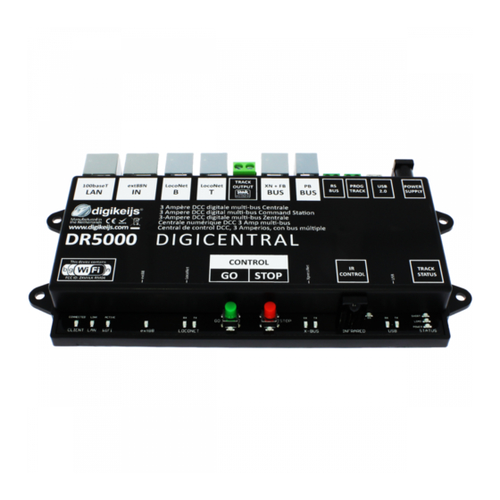
- Page 7 DR5000 DIGICENTRAL 2.3 Hardware overview 1 LAN connection (100 MBit) 2 S88-N connection 3 LocoNet® B connection (LocoNet boosters) 4 LocoNet® T connection (LocoNet equipment) 5 Track output 6 Feedback bus (X –Bus® & R-Bus®) 7 Booster Bus (B-Bus®) 8 RS-Bus®...
- Page 8 Track voltage As standard the DR5000 comes with a 19 volts switched and rectified power supply with a power of at least 3.5 amps. Using another rectified power supply is possible provided this has a minimum voltage of 15 volts/DC and maximum voltage of 20 volts/DC.
- Page 9 DR5000 DIGICENTRAL 2.5 Compatibility The following table shows which products are or are not compatible with the DR5000. Should you have tested a product we would like to hear, of course. You can pass this information via the following link: support@digikeijs.com...
- Page 10 DR5000 DIGICENTRAL CONFIGURATION SOFTWARE www.digikeijs.com P 10...
- Page 11 3.1 Introduction To communicate with the DR5000 through the configuration software or a train control program, a USB connection with the PC is required. (The following chapters describe how it can be done through Wi-Fi or LAN). To achieve this, you need the accompanying USB cable with a mini connector, a so-called USB A to USB mini cable.
- Page 12 After you have successfully downloaded the software it is important to unpack the downloaded file first and save it to your hard drive. Then start the installation by double clicking on “setup” or “setup.exe”. Ensure that you always have administrator rights on your PC. Important! Only connect the DR5000 after the installation of the Software and Drivers was successful. www.digikeijs.com P 12...
- Page 13 DR5000 DIGICENTRAL After a few seconds the following screen appears. Click on “Next”. If you want to change the location where the software is installed you can do so in the following screen. If there is no need it is best to leave the settings as they are and click “Next”.
- Page 14 Below you will find an overview of the settings. Click on “install” if you agree. Now the configuration software is installed, Windows will ask you a few times if you trust the software from Digikeijs. Once this has been done, the last screen appears. Press “Finish” and the drivers and the configuration program will now be installed.
- Page 15 Windows will “detect” the new hardware and install the drivers. Wait until this process is completed and you get a message from Windows that the hardware is properly installed. Now connect the DR5000 to your PC with the USB cable. Windows will now assign and reserve 3 COM ports.
- Page 16 DR5000 DIGICENTRAL 3.5 Software overview The different options are easy to approach by clicking on the respective connection. 1 LAN settings 2 S88-N settings 3 LocoNet B settings 4 LocoNet T settings 5 DCC settings 6 XpressNet® R-Bus® settings 7 B-Bus® settings 8 RS Bus®...
- Page 17 3.6 Restoring the factory settings It is possible to restore the settings of the DR5000 to the factory settings. Through the USB menu in the configuration software you can activate the Reset whereby the settings of the DR5000 are restored to factory settings NOTE! Restoring the factory settings has no effect on the LAN and Wi-Fi settings.
- Page 18 3.7 Updating software and firmware The development of the DR5000 software is continuing process. With firmware updates you can equip the controller with the latest software. The configuration software automatically checks for new versions at start-up or when online. New firmware is built-into the configuration tool. So first you have to install the lat- est version of the configuration software before the firmware update becomes available.
- Page 19 Should this happen then it is possible through the following steps to recover the firmware into the device. Connect the DR5000 only to the supplied power supply. Press the green button and hold it. Press the red button and hold it.
- Page 20 DR5000 DIGICENTRAL 3.9 Firmware versions Version Date Description 1.0.0 01-02-2016 Eerste release. 1.0.1 15-02-2016 New ability to reset the Wi-Fi Module to the factory settings through the Wi-Fi menu. 1.1.1 01-03-2016 Comprehensive update. All updates are displayed in the text file that is downloaded together with the new ConfigApp.
- Page 21 DR5000 DIGICENTRAL & Wi-Fi www.digikeijs.com P 21...
-
Page 22: Introduction
4.1 Introduction The DR5000 controller is equipped as standard with a built-in network router, as a result of which the controller is accessible through a LAN Network or wire- less network. This makes it possible to connect programs such as iTrain or RocRail with network support through your own internal network without using the USB cable. -
Page 23: Lan Settings
LocoNet over TCP/IP LBServer Choose this option to connect external applica- tions through LocoNet about TCP/IP Dr. Command Choose this option to connect future Digikeijs applications. If you get the error message: “”Access Error : Unauthorised, Access to this document requires a User ID.””... -
Page 24: Wi-Fi Settings
Important! It is the very important to change the standard Wi-Fi password to prevent other users connecting to your DR5000 controller. Changing this is very easy. Click on the button “Security”. Next you will see the ‘Pass Phrase’ settings in the screen below. As standard this password is ‘12345678’. -
Page 25: Error Message: "Access Error : Unauthorised
“”Error message: “Access Error: Unauthorised, Access to this document requires a User ID. ” when you try to reach the LAN or Wi-Fi settings through the DR5000 Software. This is because the log in details that the DR5000 software sends to Internet Explorer have not been accepted. - Page 26 DR5000 DIGICENTRAL CONNECTING TO THE OPERATING SOFTWARE www.digikeijs.com P 26...
-
Page 27: Introduction
Connecting through COM ports First of all you need the right COM port numbers. This can be viewed easily by connecting the DR5000 through the USB cable on your computer on which the Configuration software has been installed. Next, in the Configuration software click on the option USB 2.0. A screen will then appear stating the USB properties. - Page 28 Start Koploper and in the General menu choose a new database. In the relevant fields enter Name of database, Digital system and Port number. In the example below the name DR5000 has been chosen. For the digital system, LocoNet has been chosen and Port number COM7.
- Page 29 Open the serial tab and choose 115200 as the baud rate and the right LocoNet COM port, as explained on page 20. In the example below we’ve used COM7. Click OK and try to connect to the DR5000 by clicking on ‘connect’. In the bottom right in iTrain you can see whether this has succeeded and if iTrain is now ‘online’.
- Page 30 5.4 Connecting iTrain through LAN Connect the DR5000 to your local network and start the DR5000 Configuration Software. Next, click on the “100baseT LAN” settings. Now the ‘LAN Properties’ screen will open. At the bottom of this screen choose ‘XpressNet LAN’ in protocol settings and click on the green OK button.
- Page 31 Now start iTrain and click on the changes menu in interface. In the interface field choose N Lenz XpressNet IP/LAN. Open the tab “Network” and enter the IP address the DR5000 has received from your router. At Port enter port number 5550.
- Page 32 DR5000 DIGICENTRAL 5.5 Connecting Traincontroller through USB Start Train controller and in the menu “Railroad” choose “Setup Digital Systems”. Next, click on the button “Add” to make a new connection. In “Select Digital System” choose ‘LocoNet’. In the next screen select the corresponding LocoNet COM port.
- Page 33 Start Train controller and in the menu choose “Railroad” for “Setup Digital Systems”. Next, click on the button “Add” to make a new connection. In “Select Digi- tal System” choose ‘Lenz Digital Plus / LAN’. In the next screen, enter the IP address of the DR5000 controller.
- Page 34 DR5000 DIGICENTRAL 5.7 Connecting RocRail through LAN / USB Xpressnet Coming soon www.digikeijs.com P 34...
- Page 35 DR5000 DIGICENTRAL 5.8 Connecting RocRail through LAN / USB LocoNet Coming soon www.digikeijs.com P 35...
-
Page 36: Connect Windigipet Through Lan
Enter the following according to the image above: Digital system type: Lenz LAN/USB-Interface through LAN: active / yes IP address: “enter the IP address that the DR5000 has received from your network” TCP port 1: 5550 Transmission pause: Position indicator: active / yes Now close WinDigipet by clicking on Save &... -
Page 37: Configuration Options
DR5000 DIGICENTRAL Configuration options www.digikeijs.com P 37... -
Page 38: Ext88N
DR5000 DIGICENTRAL 7.1 ext88N The number of connected S88N feedback modules with 16 inputs The number of connected S88N feedback modules with 8 inputs The total number of connected feedback contacts First reported feedback contact of the 1st connected s88 module. -
Page 39: Loconet B
DR5000 DIGICENTRAL 7.2 LocoNet B LNCV module address reading and / or programming LocoNet reading CVs and / or program LocoNet Feedback monitor. The different colors show the different feedback busses. Advanced settings Overview of connected LocoNet Boosters. www.digikeijs.com P 39... -
Page 40: Loconet T
DR5000 DIGICENTRAL 7.2 LocoNet T LNCV module address reading and / or programming LocoNet reading CVs and / or program LocoNet feedback monitor. The different colors show the different feedback busses. Advanced settings www.digikeijs.com P 40... -
Page 41: Track Output
DR5000 DIGICENTRAL 7.4 Track Output Generate RailCom® cut-outs Polarity of the RailCom® cut-out Activate automatic RailCom polarity cut-out Maximum load that the output can deliver to the rails Short circuit delay before the controller switches off Temperature of the internal amplifier The current power that is required from the controller in milliamperes. - Page 42 DR5000 DIGICENTRAL 7.5 XN + FB BUS Switch XpressNet® on or off. Invert commands. Enable Loco info broadcast (Windigipet) Base module address for feedback messages at the Xpressnet protocol. Switch on the detection of the connected R-Bus® feedback modules. Time interval between reports of the rbus(r) modules.
-
Page 43: Pb-Bus
DR5000 DIGICENTRAL 7.6 PB-Bus Short circuit delay in milliseconds. A number of detected B-Bus® boosters. Booster number with short circuit. www.digikeijs.com P 43 ® R-Bus, B-Bus are trademarks which are registered in the name of Modelleisenbahn GmbH. XpressNet and RS-Bus is a trademark registered in the name of Lenz... -
Page 44: Rs-Bus
DR5000 DIGICENTRAL 7.7 RS Bus® The RS-Bus is not yet implemented in the software. This will be implemented in the next firmware update. www.digikeijs.com P 44 ® R-Bus, B-Bus are trademarks which are registered in the name of Modelleisenbahn GmbH. XpressNet and RS-Bus is a trademark registered in the name of Lenz... -
Page 45: Programming Track
DR5000 DIGICENTRAL 7.8 Programming Track Choice from Service or POM (Program on Main) programme Address number CV number CV Value Bits Status of reading out or programming The measured load on the programming track during reading out or programming www.digikeijs.com... - Page 46 The assigned COM ports on the DR5000 controller The current firmware version of your DR5000 The most recently available firmware version Update the firmware of the DR5000 to the last version Status of the firmware update Restoring the factory settings of the DR5000 www.digikeijs.com...
-
Page 47: Power
DR5000 DIGICENTRAL 8.0 Power The Power settings are not yet implemented in the software. This will be implemented in the next firmware update. www.digikeijs.com P 47... -
Page 48: Infrared Control
DR5000 DIGICENTRAL 8.1 Infrared control Decoder addresses linked to the preferred channel on the infrared remote control. Point addresses linked to the preferred channel on the infrared remote control. www.digikeijs.com P 48... -
Page 49: Controlling
DR5000 DIGICENTRAL Controlling www.digikeijs.com P 49... -
Page 50: Control Options
Use this to open a software-based controller to drive a locomotive. Use this to open a software-controlled switch board to operate points or accessories. The current processor temperature of the DR5000. The current H Bridge temperature of the DR5000. www.digikeijs.com P 50... -
Page 51: Connection Examples
DR5000 DIGICENTRAL Connection Examples www.digikeijs.com P 51... -
Page 52: S88N Feedback Modules (Dr4088Cs)
These feedback modules are connected to each other with STP cables and with the DR5000 controller. You can connect a maximum of 16 S88N modules with 16 inputs on the controller. In total there are 256 feedback points through the S88N/ext88N input. -
Page 53: Loconet Boosters
DR5000 in conjunction with the DR5033 LocoNet Booster You can increase the maximum power of the DR5000 easily by using the DR5033 LocoNet booster. Each booster has a power of 3 amps. In addition, the DR5033 booster has an auto- matic phase rotation. -
Page 54: Loconet Feedback Modules
LocoNet modules are used. These feedback modules are connected to each other with LocoNet cables and to the DR5000 controller. You can connect a maximum of 128 modules with 16 inputs to the LocoNet T input of the controller. -
Page 55: Xpressnet® And R-Bus® Feedback Modules
In this example the DR4088RB feedback modules are used. These feedback modules are con- nected to each other with R-Bus cables and to the DR5000 controller. You can connect a maximum of 10 modules with 16 inputs on the R-Bus® input of the controller. In total there are 160 feedback points. - Page 56 DR5000 in conjunction with the DR5033 B-BUS® Booster You can increase the maximum power of the DR5000 easily by using the DR5033 B-BUS® booster. Each booster has a power of 3 amps. In addition, the DR5033 booster has an auto- matic phase rotation.
Need help?
Do you have a question about the DR5000 and is the answer not in the manual?
Questions and answers