Table of Contents
Advertisement
1.
Introduction ....................................................... 1
2.
3.
Explanation of Controls and Indicators ........................ 3
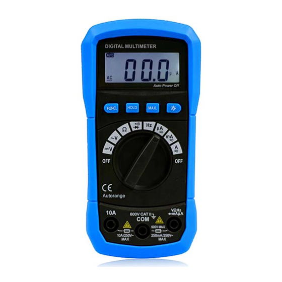
3-1. Product illustration
3-2. Functional push button ........................................... 4
3-3. LCD display ....................................................... 5
4.
Specification ....................................................... 5
4-1. General Specification ............................................. 6
4-2. Electrical Specification ........................................ 7- 9
5.
Measurement operation ......................................... 9
5-1 DC voltage & AC voltage measurement ..................... 9
5-2. Resistance measurement ....................................... 10
5-3. Diode & Continuity check ..................................... 11
5-5. DC/AC µA or mA measurement ............................. 12
5-6. DC/AC 10A measurement .................................... 12
6-2. Replacing the fuse
Table of Contents
........................................................ 2
.............................................. 3
....................................................... 13
........................................... 13
.............................................. 13
............. 11
............... 12
............................... 13
Advertisement
Table of Contents

Related Manuals for Bside ADM01

Summary of Contents for Bside ADM01
-
Page 1: Table Of Contents
5-2. Resistance measurement …………………………….….. 10 5-3. Diode & Continuity check ………………………..…..… 11 5-4. Frequency Measurement …….…… 11 [ Only for ADM01 ] 5-5. DC/AC µA or mA measurement ………………….……. 12 5-6. DC/AC 10A measurement …………………………..…. 12 5-7 Temperature measurement ………..…. 12 [ Only for ADM02 ] 6. -
Page 2: Introduction
Introduction This manual is used to ADM01 and ADM02 Digital Muti Meter only. This Meter is a handheld and battery operated Digital MultiMeter(DMM) with multi function. This Meter is designed to meet IEC61010-1 & CAT II 600V over voltage category and double insulation. -
Page 3: Explanation Of Controls And Indicators
voltage capacitors before testing continuity, diode, resistance, capacitance or current. Note international Electrical Symbol. Dangerous Ground Voltage AC Alternating Warning current see explain in manual DC (Direct Double insulation Current) AC or DC Fuse Measurement category(over voltage category): This instrument is meet the safety condition of II. -
Page 5: Functional Push Button
1. LCD display 2. “MAX” push button 3. “BACK LIGHT” push button 4. ‘HOLD” push button 5. “FUNC” Push button 6. Rotary Switch (Knob) 7. “V/Ω/HZ/uA/mA/Temp”Input terminal [‘Hz’ is for ADM01 and ‘Temp’ is for ADM02] 8. “COM” input terminal 9. “10A” input terminal 3-2. Functional push button... - Page 6 3-3. Display indicators Fig. 2 Indicator Meaning DC voltage or current AC voltage or current Diode Maximum value HOLD Data hold Low battery indicator MKΩ Ω KΩ MΩ is unit of resistance The unit of temperature ℃/℉ (℃: Centigrade; ℉: Fahrenheit)
-
Page 7: Specification
mV ,V is unit of voltage µmVA µA, mA, A is unit of current - Indicate negative reading 4.Specification 4-1. General Specification ● Auto ranging DMM , that full scale is 2000 counts ● Display : 3 1/2 digit LCD display.. ●... -
Page 8: Electrical Specification
● Power Supply: 9V Battery(6F22 or 1604A Type) x 1pc. ● Safety Class: IEC 61010-1, CAT II 600V. ● Dimension(L x W x H) & Weight:140 x 67 x 30mm, Approx. 112g 4.1.1 Accessary: 1. User’s Manual ---------------------------- 2. Test lead ---------------------------- 1set 3. - Page 9 4.2.3 Resistance Accuracy Range Resolution 200Ω 0.1Ω 2kΩ 0.001kΩ ±(0.8% rdg + 2dgt) 20kΩ 0.01kΩ 200kΩ 0.1kΩ 2MΩ 0.001MΩ ±(1.0% rdg + 2dgt) 20MΩ 0.01MΩ 4.2.4 Diode check Resolution Function Range 0.001V Will display the forward drop voltage. * Operating current:about 1mA * Open circuit voltage:about 1.48V 4.2.5 Continuity Rang...
- Page 10 10A range. * Max input current::250mA at ‘mA’ input terminal and 10A at ‘10A’ input terminal... * Frequency response:40 ~ 400Hz 4.2.8 Frequency (For ADM01) Range Accuracy Resolution 20kHz 10 KHz ±(1.5%rdg+5dgt) * Sensitivity: 0.8V 4.2.9 Temperature...
-
Page 11: Measurement Operation
You can selecting [℃] or [℉] by “FUNC” key. Range -20℃ ~ 1000℃ Resolutio 1℃ -20℃~0℃ ((5% rdg + 4dgt) Accuracy 0℃~400℃ ((2% rdg + 3dgt) 400℃~1000℃ ((3% rdg + 3dgt) Fahrenheit Temperature [℉] Range 0℉~1800℉ Resolutio 1℉ -0℉~50℉ ((5% rdg + 4dgt) Accuracy 50℉~750℉... -
Page 12: Resistance Measurement
When DC or AC voltage measurement has been completed, disconnect the connection between the testing lead and the circuit under testing. 5-2. Resistance measurement The resistance range are: 200.0Ω, 2.000KΩ,20.00KΩ, 200.0KΩ , 2.000MΩ.20.00MΩ. To measure resistance, connect the meter as follows: ①... -
Page 13: Frequency Measurement [ Only For Adm01]
② The buzzer sound if the resistance of a circuit under test is less than 100Ω. 5-4. Frequency measurement [ Only for ADM01] ① Set the rotary switch to “Hz” position. ② Insert the red test lead into the “ VΩHz” input terminal and the black test lead into the “COM”... -
Page 14: Dc/Ac 10A Measurement
properDC/AC µA or DC/AC mA position. ② Break the current path to be tested. Connect the red test lead to the more positive side of the break and the black test lead to the more negative side of the break. ③... -
Page 15: Cleaning And Decontamination
③ Remove old battery and snap new one into battery holder 6-2. Fuse replacement Replacing the defective fuse should the done according to the following procedure. ① To avoid electrical shock, remove the test lead and any input signal before opening the bottom case. ②...
Need help?
Do you have a question about the ADM01 and is the answer not in the manual?
Questions and answers