Advertisement
TEL/jlRE"
Introduction
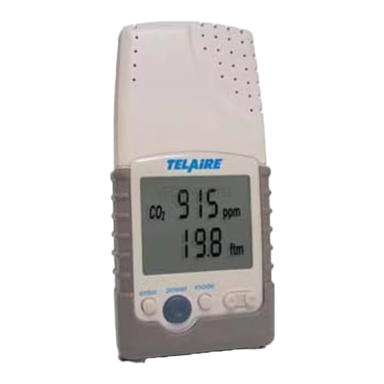
The Telaire ® 7001 CO 2 /T emperature monitor (shown in Fi
below) is an easy to use hand-held instnunent, which provides stable and
highly accurate readings due to Telaire patented dual beam NDIR
teduiology. The monitor, equipped with a 0-4 V output, is ideal for lo11g
tem1 monitoring and recording.
2 3 4 5
I
Front View
1. Display
2. Enter Button
3. Power Button
4. Mode Button
S. Up/Down Button
Figure 1: Tel a ire 7001 C0
Startup Procedure
The following procedures describe Batte1y Operation, Low Batte1y and
AC Power Operation.
Battery Operation
For po1table use, the monitor will operate up to 70 hours on 4 AA
industrial alkaline batteries. The batteries can be installed by removing
the cover from the batteiy compartment and following the diagram
displayed on the back of the monitor (see Rear View in Fi
Low Battery
The low batte1y signal fl a shes when less than 30 minutes of batteiy life
remains. At this point, the batteries should be replaced or the AC adapter
should be used as a substitute. If ordi11a1y operation continues, the
monitor will become inoperable and only the LOW BATT si
display on the LCD.
AC Power Operation
The sensor is shipped with a 6V DC, 500 mA AC/DC adapter. To use the
adapter, connect the plug into the back of the monitor and plug the
tra11sfom1er into any standaid wall outlet.
Note: It is important to use the adapter supplied with the
Telaire 7001. Using the wrong adapter may cause
damage to the monito1: Also, the batte,y operation ,vi/I
not function as a backup during a power loss.
Test Equipment Depot - 800.517.8431 - 99 Washington Street Melrose, MA 02176
u· e 1
gt
-----9
-----10
Rear View
6. BatterY Compartment
7. Adapter Connection
8. RJ-45 Connection
9. Cal Button (under cover)
10. Gas Connection
11. Kickstand
tT emperature Monitor
2
u· e 1 above).
gt
al will
gn
TestEquipmentDepot.com
®
Telaire
7001 CO 2 and Temperature Monitor
Power-Up Procedure
To power-up the monitor, do as follows:
1. Press the Power Button and a 2 second delay will occur before the
display becomes visible.
2. A duration of 10 seconds will elapse before displaying the cw1· e nt
CO2 readings.
3. WARM-UP will display for approximately 1 minute. Dwi.ng this
time, adjustments cannot be made to the sensor.
Display Features and Modes
•
WARM-UP- hldicates a 1 minute wam1-up
•
ON LINE - hldicate when a PC is communicating to the sensor via
RJ45 po1t
•
Normal Operating Mode - After wann-up the sensor will stabilize
and display the current conditions
Adjustment Modes
By pressing the mode button, you can scroll thi o ugh the adjustment
modes. Once the desired mode is displayed, press Enter to make
adjustments. Press Enter again to save and leave the adjustment mode.
The following are the adjustment modes:
•
ELEVATION - Used to compensate for elevation changes.
•
CALIBRATION - Used when calibrating .
•
TEMPERATURE -Used for temperature calibration
•
OUTSIDE - To manually input CO2 levels for the CFM ventilation
rate.
•
CALIBRATION IN PROGRESS - Displays dwi.ng calibration .
Display Features
•
CO2 Readings (Upper Display) - Remain visible at all times
•
Temperature and Ventilation Rates (Lower Display)- The Up/
Down a1rnws allow you to toggle thiough the Temperatw· e and
Ventilation modes. When pressing the Up a1rnw, the display will go
tlu· o ugh the following sequence:
•c
Temp
> Temp °F > Vent Rate 1/p/s > Vent Rate cfm/p > Blank
•
US Standard to Metric Conversion - The Temperature, Ventilation
rates, and Elevation Readings can be viewed in US Standard or
Metric Readings. The Temperattu· e is co11ve1ted from Falu· e nheit
(°F) to Celsius (
C); the Ventilation Rates are co11ve1ted from
0
Cubic Feet Per Minute
Per
s) and the Feet (ft) to Meters (m).
User Instructions
Person
(
cfm/p) to Liters Per
Second
(1/p/
Advertisement
Table of Contents

Related Manuals for Telaire 7001

Summary of Contents for Telaire 7001
-
Page 1: User Instructions
7001 CO 2 and Temperature Monitor User Instructions Introduction Power-Up Procedure The Telaire ® 7001 CO 2 /T emperature monitor (shown in Fi u· e 1 To power-up the monitor, do as follows: below) is an easy to use hand-held instnunent, which provides stable and highly accurate readings due to Telaire patented dual beam NDIR 1. - Page 2 Ventilation Rate (cfm/p) The ventilation rate is defined as the value that represents how much Before using the Telaire 7001 monitor, it is important to make the outside air is being introduced on a CFM per person basis. elevation correction outlined below.
-
Page 3: Temperature Adjustment
View™ Real-Time Graphing/Calibration Software 2080 - This If you are calibrating to ambient conditions, make sure the sensor is software allows the Telaire 7001 Monitor to log directly to a displaying a stable reading. Avoid breathing in the area of the Windows compatible PC and graph concentrations in real time monitor. -
Page 4: Specifications
Specifications Display Options °F, °C, or OFF. Set with panel button The Telaire 7001 Monitor meets all the specifications listed below. Accuracy Method ±2 °F (±1 °C) Dual Beam Absorption Infrared™ Response Time Display - LCD 20-30 minutes (case must equilibrate with environment) •... -
Page 5: Storage Temperatures
This product is covered by one or more of the following patents: Certifications: 5,650,624/5,721,430/5,444,249/5,747,808/5,834,777/5,163,332/ • 5,340,986/5,502,308/6,344,798/6,023,069/5,370,114/5,601,079/ FCC Class 15 Part B • 5,691,704/5,767,776/5,966,077/6,107,925/5,798,700/5,945,924/ 5,592,147/6,255,653/6,250,133/6,285,290 Test Equipment Depot - 800.517.8431 - 99 Washington Street Melrose, MA 02176 TestEquipmentDepot.com Amphenol Advanced Sensors Telaire 7001 CO and Temperature Monitor Page 5...
Need help?
Do you have a question about the 7001 and is the answer not in the manual?
Questions and answers