
Related Manuals for Ziegler mfm 3480

Summary of Contents for Ziegler mfm 3480
- Page 1 ZIEGLER mfm 3480 Digital Multifunction Instrument - Touch Screen Graphics LCD www.ziegler-instruments.com User Manual Version: 15001123 Rev.A - 08/2012...
-
Page 3: Table Of Contents
Single Phase Single Phase Touch Screen Digital Multi-function Meter Installation & Operating Instructions Section Contents Introduction Measurement Reading Screens Programming 3.1 Password Protection 3.1.1 Change Password 3.2 Menu selection 3.2.1 System Parameter selection screen 3.2.1.1 Potential transformer Primary value 3.2.1.2 Potential transformer secondary value 3.2.1.3 Current transformer Primary value 3.2.1.4 Current transformer Secondary value 3.2.1.5 Demand integration time... - Page 4 3.2.3 Reset Parameter selection screen 3.2.3.1 Resetting Parameter 3.2.4 Output Option selection screen (menu) 3.2.4.1 Relay 1 output selection menu 3.2.4.1.1 Pulse output 3.2.4.1.1.1 Assignment of Energy to Pulse (Relay 1) 3.2.4.1.1.2 Pulse Duration Selection 3.2.4.1.1.3 Pulse Rate 3.2.4.1.2 Limit output 3.2.4.1.2.1 Assignment of Limit Output1 to Parameter 3.2.4.1.2.2 Limit Configuration 3.2.4.1.2.3 Trip point selection...
-
Page 5: Introduction
Phaser Diagram Installation 12.1 EMC Installation Requirements 12.2 Case Dimensions and Panel Cut-out 12.3 Wiring 12.4 Auxiliary Supply 12.5 Fusing 12.6 Earth / Ground Connections Connection Diagram Specification Connection for Optional Pulse output / RS 485 /Analog Ouput 1. Introduction This instrument is a panel mounted 96 x 96mm DIN Quadratic Digital metering system for the measurement important electrical parameters like AC voltage,... - Page 6 TABLE 1: Units of Measured Parameters Measurement Volts System Voltage Amps System Current Frequency Kwatts System Active Power KVAr System Reactive Power System Apparent Power System Power Factor System Phase Angle Degree Active Import Energy (8 Digit resolution) Active Export Energy (8 Digit resolution) Reactive Import Energy (8 Digit resolution) kVArh Reactive Export Energy (8 Digit resolution)
-
Page 7: Measurement Reading Screens
Units of Measured Parameters Measurement Counts Number of Interruptions System Voltage THD System Current THD Pictorial representation of Phaser Diagram Pictorial representation of Voltage Waveform Pictorial representation of Current Waveform Pictorial representation of VA Waveform Measurement Reading Screens In normal operation the user is presented with one of the measurement reading screens out of several screens. - Page 8 Screen 5 : Screen 6 : Screen 4 : System Run Hour System ON Hour Phaser Diagram V/Div Inductive 124.5 Capacitive SYSTEM RUN HOUR SYSTEM ON HOUR LINE-NEUTRAL VOLTAGE LINE-NEUTRAL VOLTAGE LINE-NEUTRAL VOLTAGE LINE-NEUTRAL VOLTAGE LINE-NEUTRAL VOLTAGE LINE-NEUTRAL VOLTAGE +P,+Q -P,+Q 1.500 A/Div...
- Page 9 Screen 14 : Pictorial representation Line-Neutral Voltage Screen 13 : Voltage Waveform (Only accessed (Displayed after touching any where Phase Voltage % THD through voltage submenu list) in the row shown in screen 12) LINE-NEUTRAL LINE-NEUTRAL VOLTAGE LINE-NEUTRAL VOLTAGE LINE-NEUTRAL VOLTAGE PHASE VOLTAGE % THD VOLTAGE WAVEFORM LINE-NEUTRAL VOLTAGE...
- Page 10 Screen 21 : Phase Angle Screen 22 : Phase Power Screen 23 : Factor Current Demand PHASE POWER FACTOR PHASE ANGLE LINE-NEUTRAL VOLTAGE LINE-NEUTRAL VOLTAGE LINE-NEUTRAL VOLTAGE LINE-NEUTRAL VOLTAGE LINE-NEUTRAL VOLTAGE LINE-NEUTRAL VOLTAGE CURRENT DEMAND LINE-NEUTRAL VOLTAGE LINE-NEUTRAL VOLTAGE LINE-NEUTRAL VOLTAGE 0.000 0.000 0.000...
- Page 11 Screen 36 : Screen Screen 35 : Reactive Energy Export Apparent Energy Reactive Energy Import REACTIVE ENERGY IMPORT LINE-NEUTRAL VOLTAGE LINE-NEUTRAL VOLTAGE LINE-NEUTRAL VOLTAGE REACTIVE ENERGY EXPORT LINE-NEUTRAL VOLTAGE LINE-NEUTRAL VOLTAGE LINE-NEUTRAL VOLTAGE APPARENT ENERGY LINE-NEUTRAL VOLTAGE LINE-NEUTRAL VOLTAGE LINE-NEUTRAL VOLTAGE 0.000 0.000 0.000...
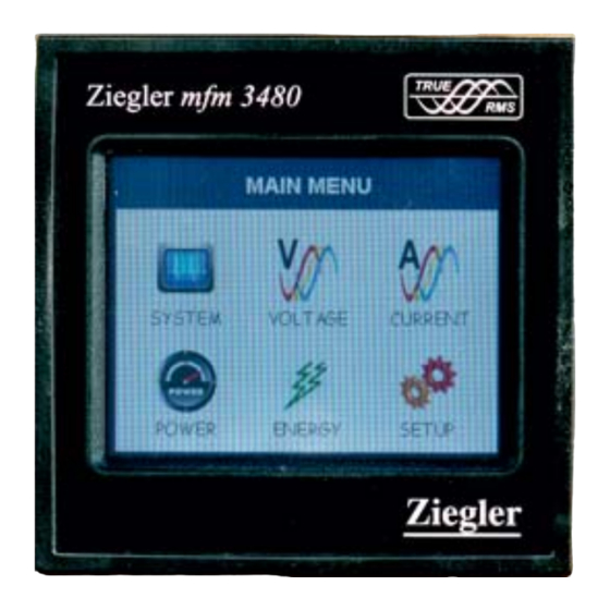
- Page 12 Parameter Screens MAIN MENU RESET CHANGE COMMUNICATION POWER ENERGY SYSTEM VOLTAGE CURRENT OPTIONS PASSWORD PARAMETERS (Sec 3.1) (Sec 3.2.4) PHASE REACTIVE SYSTEM Line to Neutral ACTIVE ENERGY SYSTEM TYPE Line Current POWER IMPORT (Sec 3.2.1.1) PARAMETERS VOLTAGE PHASE APPARENT ACTIVE ENERGY Max.
-
Page 14: Programming
3. Programming The following sections comprise step by step procedures for configuring the instrument for individual user requirements. To access the set-up screens touch on the “ SETUP ” icon in Main Menu. This will take the User into the Password Protection Entry Stage(Section 3.1). 3.1. - Page 15 After entering the complete password user needs to confirm password SETUP by touching “ key”. 1234 ENTER ENTER BACK Password confirmed. SETUP If Entered password is correct then “Password Accepted” is displayed PASSWORD ACCEPTED on screen & user will enter into setup menu. ENTER BACK Password Incorrect.
-
Page 16: Change Password
3.1.1 Change Password Change Password Option is the second last option in list of “SETUP” submenu, so can be accessed by a simple touch anywhere in “ Change PASSWORD ENTER CURRENT PASSWORD Password” row. In this screen user first needs to enter the current password. ENTER BACK After input of correct password, “PASSWORD ACCEPTED”... -
Page 17: Potential Transformer Primary Value
3.2.3 RESET PARAMETERS 3.2.4 OUTPUT OPTIONS 3.2.5 BRIGHTNESS & CONTRAST Touching on SYSTEM PARAMETER will open the system parameters list screen.Then these screens from particular parameter may be scrolled through one at a time in incremental order by touching the “ key”... -
Page 18: Potential Transformer Secondary Value
Valid range of PT primary setting value is from 100 VL-L to 692.8 KVL-L. LINE-NEUTRAL VOLTAGE LINE-NEUTRAL VOLTAGE LINE-NEUTRAL VOLTAGE PT PRIMARY INVALID VALUE If value outside the range is entered, It will display “INVALID VALUE” followed by correct range of parameter. ENTER BACK 3.2.1.2 Potential Transformer secondary Value... -
Page 19: Current Transformer Primary Value
3.2.1.3 Current Transformer Primary Value The nominal Full Scale Current that will be displayed as the Line currents. This screen enables the user to display the Line currents inclusive of any transformer ratios, the values displayed represent the Current in Amps. This screen can be accessed only from system parameters list menu. -
Page 20: Current Transformer Secondary Value
3.2.1.4 Current Transformer Secondary Value This screen is used to set the secondary value for Current Transformer. options: 1 AMPERE & 5 AMPERE are displayed on screen. CT SECONDARY LINE-NEUTRAL VOLTAGE LINE-NEUTRAL VOLTAGE LINE-NEUTRAL VOLTAGE LINE-NEUTRAL VOLTAGE LINE-NEUTRAL VOLTAGE LINE-NEUTRAL VOLTAGE CT SECONDARY Touching radio button in front of... -
Page 21: Low Current Noise Cutoff
While in Auto-scrolling mode, touch sense for entire screen will be disabled except for the top right most corner where “A” symbol would be displayed stating that meter is in Auto- scroll mode. Touching on “A” will show two options “ON” and “OFF”. Touching on “ON” will continue auto scrolling &... -
Page 22: Energy Digit Reset Count
3.2.1.9 ENERGY DIGIT RESET COUNT (ROLLOVER COUNT) This screen enables the user for setting maximum energy count after which energy will rollover to zero depending on the setting of Wh, kWh & Mwh in Energy on RS485 option. If Energy on RS485 is in WATT then rollover count can be from 7 to 14 DIGITS. -
Page 23: Address Setting
3.2.2.1 Rs485 Address Setting This screen applies to the RS 485 output only. This screen allows the user to set RS485 address parameter for the instrument. LINE-NEUTRAL VOLTAGE LINE-NEUTRAL VOLTAGE LINE-NEUTRAL VOLTAGE RS485 ADDRESS ENTER RS485 ADDRESS This screen can be accessed only from Communication Parameters List menu. - Page 24 3.2.2.3 RS 485 Parity & Stop bit Selection This screen allows the user to set Parity & number of stop bits. Four options: ODD PARITY WITH ONE STOP BIT, NO PARITY RS485 PARITY & STOP BITS LINE-NEUTRAL VOLTAGE LINE-NEUTRAL VOLTAGE LINE-NEUTRAL VOLTAGE LINE-NEUTRAL VOLTAGE LINE-NEUTRAL VOLTAGE...
- Page 25 Touching on any parameter will display the confirmation dialog, now a touch on “ key” will confirm the resetting of that particular RESET PARAMETERS LINE-NEUTRAL VOLTAGE LINE-NEUTRAL VOLTAGE LINE-NEUTRAL VOLTAGE RESET ALL Parameter. 0.000 0.000 0.000 RESET ALL ENERGIES RESET DEMAND PARAMETERS ARE YOU SURE YOU WANT TO RESET ALL Touching on “...
- Page 26 3.2.4.1.1.1 Assignment of Energy to pulse output (Relay 1) : This screen allows the user to assign energy to pulse output (for Relay 1) Following six options are displayed:- Apparent Energy Import Energy ( Active ) RELAY-1 ENERGY ASSIGNMENT LINE-NEUTRAL VOLTAGE LINE-NEUTRAL VOLTAGE LINE-NEUTRAL VOLTAGE LINE-NEUTRAL VOLTAGE...
- Page 27 3.2.4.1.2 Limit output This screen is for Limit output mode selection. It allows the user to set Limit output corresponding measured value. After entering in Limit Output first time(was disabled previously), only “PARAMETER:” is displayed on screen. Now a simple touch on “PARAMETER:” will open list of parameters, Refer Table 2 “Parameter for Analog &...
- Page 28 3.2.4.1.2.3 Trip point selection This screen applies to the Trip point selection. This screen allows the user to set Trip point for instrument in %. This screen can be accessed only from Limit Output settings list menu. LINE-NEUTRAL VOLTAGE LINE-NEUTRAL VOLTAGE LINE-NEUTRAL VOLTAGE RELAY-1 TRIP POINT Here a 0 to 9 digit input keypad is provided to set value of Trip Point,...
- Page 29 The allowable range is 0.5% to 50 % of Trip point If value outside this range is entered, it will display “INVALID VALUE” LINE-NEUTRAL VOLTAGE LINE-NEUTRAL VOLTAGE LINE-NEUTRAL VOLTAGE RELAY-1 HYSTERESIS INVALID VALUE followed by correct range of parameter. ENTER BACK 3.2.4.1.2.5 Energizing Delay time.
- Page 30 3.2.4.1.2.6 De-Energizing Delay time This screen allows the user to set De-Energizing Delay time for Relay 1 Limit Assigned Parameters . This screen can be accessed only from Limit Output settings list menu. RELAY-1 DE-ENERGIZING DELAY LINE-NEUTRAL VOLTAGE LINE-NEUTRAL VOLTAGE LINE-NEUTRAL VOLTAGE Here a 0 to 9 digit input keypad is provided to set value of Delay, &...
- Page 31 3.2.4.4 Parameter setting for Analog Output 2 ( Optional ) This option allows the user to set analog output to corresponding measured parameter. simple touch on “ANALOG-2”row will open screen having list of parameters.( Refer table2 “ Parameter for Analog & Limit output ”) Touch on “...
- Page 32 LINE-NEUTRAL VOLTAGE LINE-NEUTRAL VOLTAGE LINE-NEUTRAL VOLTAGE LINE-NEUTRAL VOLTAGE LINE-NEUTRAL VOLTAGE LINE-NEUTRAL VOLTAGE CT SECONDARY LINE-NEUTRAL VOLTAGE LINE-NEUTRAL VOLTAGE LINE-NEUTRAL VOLTAGE LINE-NEUTRAL VOLTAGE LINE-NEUTRAL VOLTAGE LINE-NEUTRAL VOLTAGE LINE-NEUTRAL VOLTAGE LINE-NEUTRAL VOLTAGE LINE-NEUTRAL VOLTAGE LINE-NEUTRAL VOLTAGE LINE-NEUTRAL VOLTAGE LINE-NEUTRAL VOLTAGE CT SECONDARY CT SECONDARY LINE-NEUTRAL VOLTAGE LINE-NEUTRAL VOLTAGE...
- Page 33 5 Run Hour This Screen shows the total no. of hours the load is connected Even if the Auxiliary supply is interrupted count of Run hour will be SYSTEM RUN HOUR LINE-NEUTRAL VOLTAGE LINE-NEUTRAL VOLTAGE LINE-NEUTRAL VOLTAGE maintained in internal memory & displayed in the format “hours. min”. 0.000 0.000 0.000...
- Page 34 8. Analog Output ( optional ) : This module provides two d.c. isolated outputs .There are two output options 1) Two 0 - 1mA outputs , internally powered . 2) Two 4 - 20mA outputs , internally powered . The 0 -1mA output module has an 0V return on each end of the 4 way connector ( Please refer section 15 for connection details ) On both modules the output signals are present on pins A1(Analog Output 1) &...
- Page 35 Diagram 2 : ( 0 - 1 mA ) 0 (0.5 mA) 270 (0.25 mA) 90 (0.75 mA) 181 (0 mA) 180 (1 mA) TABLE 2 : Parameter for Analog & Limit output Range Parameter Parameter Analog Output Limit Output –...
- Page 36 Range Parameter Parameter Analog Output Limit Output WATT DEMAND EXPORT 0 - 120 % 10 - 120 % WATT MAX DEMAND EXP. 0 - 120 % 10 - 120 % 10 - 120 % 0 - 120 % VA DEMAND 0 - 120 % 10 - 120 % VA MAX DEMAND...
- Page 37 Energy Pulse Rate Divisor TABLE 3 : 1.For Energy Output in Wh 2. For Energy Output in Kwh Pulse rate Pulse rate Divisor Pulse System Power* Divisor Pulse System Power* 1per Wh Up to 3600W 1 per kWh Up to 3600W 1per kWh Up to 3600kW Up to 3600kW...
- Page 38 Divisors 100 CT secondary = 1A Max pulse rate 3600 pulses per 100Ah ** CT secondary = 5A Max pulse rate 720 pulses per 100Ah ** Divisors 1000 CT secondary = 1A Max pulse rate 3600 pulses per 1000Ah ** CT secondary = 5A Max pulse rate 720 pulses per 1000Ah ** Pulse duration 60 ms, 100 ms or 200 ms **No.
- Page 39 Trip point: Trip point can be set in the range of 10% to 120 % of nominal value for Hi-Alarm & 10% to 100 % of nominal value for Lo-Alarm. Hysteresis: Hysteresis can be set in the range of 0.5% to 50 % of set trip point . If Hi-alarm Energized or Hi-alarm De-energized is selected then relay will get De-energized or Energized respectively, if set parameter value is less than Hysteresis Similarly if Lo-alarm Energized or Lo-alarm De-Energized.
- Page 40 10. RS 485 ( ModBus ) Output : This instrument supports MODBUS (RS485) RTU protocol( 2-wire ) . Connection should be made using twisted pair shielded cable. All "A" and "B" connections are daisy chained together. The screens should also be connected to the “Gnd” terminal. To avoid the possibility of loop currents, an Earth connection should be made at one point on the network.Loop (ring) topology does not require any termination load.
- Page 41 The each byte in RTU mode has following format: 8-bit binary, hexadecimal 0-9, A-F 2 hexadecimal characters contained in each 8-bit field of the message Format of Data Bytes 4 bytes (32 bits) per parameter. Floating point format ( to IEEE 754) Most significant byte first (Alternative least significant byte first) Error Checking Bytes 2 byte Cyclical Redundancy Check (CRC)
- Page 42 This function code is not supported by the instrument. Illegal function Attempt to access an invalid address or an attempt to read Illegal Data or write part of a floating point value Address Attempt to set a floating point variable to an invalid value Illegal Data Value Accessing 3 X register for reading measured values:...
- Page 43 Number of register Hi : Most significant 8 bits of Number of registers requested. Number of register Lo : Least significant 8 bits of Number of registers requested. (Note : Two consecutive 16 bit register represent one parameter.) Response: Volt3 (219.25V) 43 (Hex) 5B (Hex) 01 (Hex) 04 (Hex) 04 (Hex)
- Page 44 Address Parameter Parameter Parameter Parameter Modbus Start Address Hex Modbus Start Address Hex High Byte High Byte High Byte Low Byte (Register) 30071 Freq 30073 Wh Import 30075 Wh Export 30077 VARh Import 30079 VARh Export 30081 30083 30085 W Demand (Import) 30087 W Max Demand (Import) 30089...
- Page 45 Accessing 4 X register for Reading & Writing : Each setting is held in the 4X registers .ModBus code 03 is used to read the current setting and code 16 is used to write/change the setting. Refer Table 5 for 4 X Register addresses. Example : Reading CT Secondary System type : Start address= 2A (Hex)
- Page 46 Response: 01 (Hex) Device Address 03 (Hex) Function Code Byte Count 04 (Hex) Data Register1 High Byte 3F (Hex) Data Register1Low Byte 80 (Hex) Data Register2 High Byte 00 (Hex) Data Register2 Low Byte 00(Hex) F7 (Hex) CRC Low CRC High CF (Hex) Byte Count : Total number of data bytes received.
- Page 47 Starting Address Hi 00 (Hex) Starting Address Lo 2A(Hex) Number of Registers Hi 00 (Hex) Number of Registers Lo 02(Hex) Byte Count 04 (Hex) Data Register-1High Byte 3F (Hex) Data Register-1 Low Byte 80(Hex) Data Register-2 High Byte 00(Hex) Data Register-2 Low Byte 00(Hex) 7C(Hex) CRC Low...
- Page 48 Number of Registers Hi 00 (Hex) Number of Registers Lo 02(Hex) 60 (Hex) CRC Low CRC High 00 (Hex) Start Address High : Most significant 8 bits of starting address of the parameter requested. Start Address low :Least significant 8 bits of starting address of the parameter requested. Number of register Hi : Most significant 8 bits of Number of registers requested.
- Page 49 Parameter Modbus Start Address Hex Address Parameter Read / Write (Register) High Byte High Byte High Byte Low Byte R/Wp 40029 Analog Out 1- Para Sel R/Wp 40031 Analog Out 2- Para Sel R/Wp 40033 PT Primary 40035 CT Primary R/Wp 40037 System Power...
- Page 50 Explanation for 4 X register : Address Parameter Description 40001 Demand Reset Demand Reset is used to reset the Demand parameter. A value of zero must be Written to this register to reset the Demand period. Writing any other value will return an error. 40003 Demand Period Demand period represents demand time in minutes.
- Page 51 Address Parameter Description 40019 Rs485 Set-up This address is used to set the baud rate, Parity, Number of Code stop bits. Refer to Table 6 for details. 40021 Node This register address is used to set Device address Address between 1 to 247 . This address is used to set pulse divisor of the Pulse output.
- Page 52 Address Parameter Description 40031 Analog Out 2- This address is used to set the parameter for Analog Output 2.. Para Set Write one of the parameter no. As per the options given in Table 2 for Analog & Limit Output Parameters. Writing any other value will return an error.
- Page 53 Address Parameter Description This address is used to read and write the CT secondary value CT secondary 40043 write one of the following values to this address. 1=1A CT secondary 5=5A CT secondary writing any other value will return an error. 40045 PT secondary This address is used to read and write the PT secondary value.
- Page 54 Address Parameter Description 40059 Relay 2 This address is used to select the Relay 2 operation as output select pulse or Limit. write one of the following values to this address. 0 = Pulse output on Relay 2 128 (decimal) = Limit output on Relay 2 writing any other value will return an error.
- Page 55 Address Parameter Description 3) If password lock is present & to disable this lock first send valid password to this location then write “0000” to this location 4) If password lock is present & to modify 4X parameter first send valid password to this location so that 4X parameter will be accessible for modification.
- Page 56 Parity Decimal value Baud Rate Stop Bit 19200 9600 NONE 9600 NONE EVEN 9600 9600 4800 NONE 4800 NONE 4800 EVEN 4800 2400 NONE 2400 NONE 2400 EVEN 2400 NOTE : Codes not listed in the table above may give rise to unpredictable results including loss of communication.
- Page 57 Table 8 :Limit1 & Limit2 Configuration select Configuration Code Hi- alarm & Energized relay Hi- alarm & De-e nergized relay Lo- alarm & Energized relay Lo- alarm & De-energized relay 10.1 User Assignable Modbus Registers: This instrument contains the 20 user assignable registers in the address range of 0x200 (30513) to 0x226 (30551) (see Table 9).
- Page 58 Address Parameter Modbus Start Address (Hex) Assignable Register High Byte Low Byte (Register) Number. Assignable Reg 7 30525 Assignable Reg 8 30527 30529 Assignable Reg 9 30531 Assignable Reg 10 30533 Assignable Reg 11 Assignable Reg 12 30535 Assignable Reg 13 30537 Assignable Reg 14 30539...
- Page 59 Address Parameter Modbus Start Address (Hex) Mapping Register High Byte Low Byte (Register) Number. 40521 Mapped Add for register #0x0210 40522 Mapped Add for register #0x0212 40523 Mapped Add for register #0x0214 40524 Mapped Add for register #0x0216 40525 Mapped Add for register #0x0218 40526 Mapped Add for register #0x021A Mapped Add for register #0x021C...
- Page 60 Byte Count 04 (Hex) Voltage Data Register-1High Byte 00 (Hex) (3X Address 0x0000) Data Register-1 Low Byte 00 (Hex) Power Factor Data Register-2 High Byte 00 (Hex) (3X Address 0x001E) Data Register-2 Low Byte 1E (Hex) 6A (Hex) CRC lOW C7 (Hex) CRC High Response :...
- Page 61 Query: 01 (Hex) Device Address 04 (Hex) Function Code Start Address High 02 (Hex) 00 (Hex) Start Address Low Number of Registers Hi 00 (Hex) Number of Registers Lo 04 (Hex) ** F0 (Hex) CRC Low CRC High 71 (Hex) Start Address High : Most significant 8 bits of starting address of User assignable register.
- Page 62 Data Register-3 High Byte 3F (Hex) Data Register-3 Low Byte 80 (Hex) Power Factor 1Data Data Register-4 High Byte 00 (Hex) Data Register-4 Low Byte 00 (Hex) 79 (Hex) CRC Low CRC High 3F (Hex) User Assignable mapping Registers User Assignable Data Registers (Starting (Starting ( 4X Registers Table10 )
- Page 63 To get the data through User assignable Register use following steps: 1) Assign starting addresses(Table3) of parameters of interest to a “User assignable mapping registers” in a sequence in which they are to be accessed (see section “Assigning parameter to user assignable registers”) 2) Once the parameters are mapped data can be acquired by using “User assignable data register “...
- Page 64 Sign of Sign of Sign of Inductive / Connections Quadrant Active Reactive Power Capacitive Power ( P ) Power ( Q ) Factor ( PF ) Import Import Export Export Inductive means Current lags Voltage Capacitive means Current leads Voltage When the instrument displays Active power ( P )with “...
- Page 65 As the front of the enclosure conforms to IP54 it is protected from water spray from all directions, additional protection to the panel may be obtained by the use of an optional panel gasket. The terminals at the rear of the product should be protected from liquids. instrument should be mounted in a reasonably stable ambient temperature and where the operating temperature is within the range...
- Page 66 3. To protect the product against permanent damage, surge transients must be limited to 2kV pk. It is good EMC practice to suppress differential surges to 2kV at the source. The unit has been designed to automatically recover in the event of a high level of transients.
- Page 67 12.4 Auxiliary Supply instrument should ideally be powered from a dedicated supply, however it may be powered from the signal source, provided the source remains within the limits of the chosen auxiliary voltage. 12.5 Fusing It is recommended that all voltage lines are fitted with 1 amp HRC fuses. 12.6 Earth/Ground Connections For safety reasons, CT secondary connections should be grounded in accordance with local regulations.
- Page 68 14. Specification : Inputs Nominal input voltage (AC RMS) Phase-Neutral 57.7 to 277 V Max continuous input voltage 120% of Rated Value Max short duration input voltage 2 x Rated Value (1s application repeated 10 times at 10s intervals) Nominal input voltage burden 0.2VA approx.
- Page 69 a.c. supply burden 6.5 V A d.c. supply burden Operating Measuring Ranges Voltage 5 .. 120 % of Rated Value Current 5 .. 120 % of Rated Value Frequency 40 .. 70 Hz 0.5 Lag ... 1 ... 0.8 Lead Power Factor Accuracy Accuracy 1:...
- Page 70 ± 1 % of range Angle ± 1 % of Output end value Analog Output Total Harmonic Distortion ± 1 % ± 4 % of range. Neutral Current Accuracy 0.5: Voltage ± 0.5 % of range ± 0.5 % of range C urrent 0.15% of mid frequency Frequency...
- Page 71 Accuracy 0.2: Voltage ± 0.2 % of range ± 0.2 % of range C urrent Frequency 0.15% of mid frequency ± 0.2 % of range Active Power ± 0.2 % of range Re- Active Power ± 0.2 % of range Apparent Power ±...
- Page 72 Input waveform Sinusoidal (distortion factor 0.005) Auxiliary supply voltage Rated Value + 1 % Rated Value + 1 % Auxiliary supply frequency Voltage Range 50... 100% of Nominal Value. 60... 100% of Nominal Value for THD. Current Range 10... 100% of Nominal Value. 20...
- Page 73 0.025% / C for Voltage (50..120% of Rated Value) Temperature Coefficient (For Rated value range of use 0.05% / C for Current ( 10..120% of Rated Value ) 0... 50 C ) Error change due to variation of an 2 * Error allowed for the reference influence quantity condition applied in the test.
- Page 74 Environmental Operating temperature -10 to 55 C Storage temperature -20 to +65 C Relative humidity 0 .. 90 % RH Warm up time 3 minute (minimum) Shock 15g in 3 planes Vibration 10 .. 55 Hz, 0.15mm amplitude Enclosure ( front only ) IP 54 as per IEC 60529 Enclosure Style...
- Page 75 Programmable on site Pulse rate Divisors 1 per 10Wh (up to 3600W), 1 per 10kWh (up to 3600kW), 1 per 10MWh (above 3600 kW) 1 per 100Wh (up to 3600W), 1 per 100kWh (up to 3600kW), 1 per 100MWh (above 3600 kW) 1000 1 per 1000Wh (up to 3600W), 1 per 1000kWh (up to 3600kW),...
- Page 76 15. Connection for Optional Pulse Output / RS 485 / Analog Output ( rear view of the instrument ) 1. One Pulse Output (One Limit Output) N/O N/C COM Relay 1 2. Two Pulse Output ( Two Limit Output) N/O N/C COM N/O N/C COM Relay 2 Relay 1...
- Page 77 5. One Pulse (One Limit) + RS 485 Output N/O N/C COM RS 485 Relay 2 6. One Pulse (One Limit) + Two Analog Output N/O N/C COM A1 A2 Gnd Relay 2 0 - 1mA 7. RS 485 + Two Analog Output A1 A2 Gnd RS 485 4 -20 mA...
- Page 78 9. Two Pulse (Two Limit) + RS 485 Output N/O N/C COM N/O N/C COM RS 485 Relay 2 Relay 1 The Information contained in these installation instructions is for use only by installers trained to make electrical power installations and is intended to describe the correct method of installation for this product.
Need help?
Do you have a question about the mfm 3480 and is the answer not in the manual?
Questions and answers