
Related Manuals for CMA Dishmachines ADRIA series


Summary of Contents for CMA Dishmachines ADRIA series
- Page 1 ESPRESSO COFFEE MACHINE USE AND MAINTENANCE MANUAL instructions for the technician...
-
Page 3: Table Of Contents
Summary GENERAL WARNINGS ............................. 5 WARNINGS FOR THE INSTALLER ........................5 1. TECHNICAL CHARACTERISTICS ........................ 6 2. PREPARATION OF THE MACHINE ......................9 2.1 UNPACKING ................................9 2.2 EQUIPMENT PREPARATION ............................9 3. MACHINE INSTALLATION ........................10 3.1 POSITIONING ................................11 3.2 HYDRAULIC CONNECTION FOR AEP-SMSA AEAP-SMAT SAE-SME MACHINES ............11 3.3 HYDRAULIC CONNECTION OF AL-SMMA MACHINES ....................11 3.4 WIRING ..................................13 3.5 GAS CONNECTION (if included) ..........................13... - Page 4 SUMMARY follows 14. SOFTENERS ............................24 15. ELECTRONIC PUSH BUTTON PANELS ....................25 15.1 SAE - SME PUSH BUTTON PANEL.........................25 15.2 TH JUNIOR PUSH BUTTON PANEL ........................26 15.3 AEAP - SMAT TIMER PUSH BUTTON PANEL ......................26 16. PREPARATION OF HOT BEVERAGES ....................27 16.1 MANUAL DISPENSING OF HOT WATER ........................27 16.2 AUTOMATIC HOT WATER DELIVERY ........................27 16.3 DISPENSING STEAM .............................27...
-
Page 5: General Warnings
GENERAL WARNINGS The manufacturer of the equipment cannot be held responsible for damage caused by failure to oblige to the requirements below. WARNINGS FOR THE INSTALLER • Read this manual carefully. It provides important information on safe installation, operation and maintenance of the equipment; •... -
Page 6: Technical Characteristics
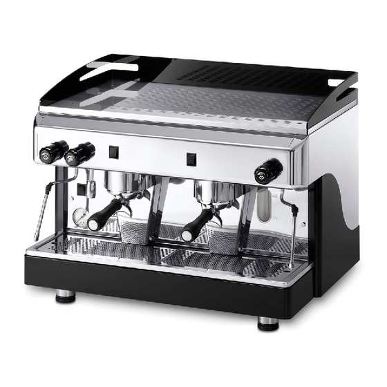
espresso coffee machine - technician instructions 1. TECHNICAL CHARACTERISTICS LEVER MACHINE Boiler level-check window (*) Pressure gauge Steam pressure gauge Steam nozzle 2-cup filter holder Manual water load Adjustable foot Hot water nozzle Gas burner viewing window (if included) Gas safety (if included) Gas ignition push button (if included) DISTRIBUTION MACHINE Machine main switch... - Page 7 espresso coffee machine - technician instructions The nameplate of the machine is fixed on the base of the frame under the drain pan. The data of the appliance can be seen also on the label located on the package of the machine.
- Page 8 espresso coffee machine - technician instructions INTERNAL COMPONENTS Boiler Delivery group Internal motor pump (if included) Boiler / motor pump pressure gauge Boiler level-check window Internal pump water attachment connection (if included) Manual water pump External pump water attachment connection Drain tub Volumetric dosing device (SAE-SME) Machine main switch...
-
Page 9: Preparation Of The Machine
espresso coffee machine - technician instructions 2. PREPARATION OF THE MACHINE 2.1 UNPACKING Open the packaging, taking care not to damage the machine. Remove the machine protections and the equipment contained in the package. Take the machine out. If there is an external motor pump, the motor and the pump are provided in a separate package. -
Page 10: Machine Installation
espresso coffee machine - technician instructions 3. MACHINE INSTALLATION DISTRIBUTION MACHINE - english... -
Page 11: Positioning
espresso coffee machine - technician instructions 3.1 POSITIONING Prepare an ample support base for the machine that is suitable to support its weight (1); it is important for all terminals of connections to the water mains (16), to the electrical mains (9) and to the gas mains (in included), to be easily reachable and in any case in the immediate vicinity of the machine. - Page 12 espresso coffee machine - technician instructions ATTENTION During the installation of the appliance, only the components and materials supplied with the appliance are to be used. Should the use of other components be necessary, the installer must verify their suitability to be used in contact with water used for human consumption.
-
Page 13: Wiring
espresso coffee machine - technician instructions 3.4 WIRING It is necessary to link a safety main switch (A) on the electric panel, as required by standard regulations. Machine with INTERNAL MOTOR PUMP Connect the power cable as set forth in the chapter "Electrical diagrams" (the cable has a cross-section and number of wires based on the power and voltage of the machine). - Page 14 espresso coffee machine - technician instructions • Connection is made with a flexible hose: - use a hose that meets the standards in use (it is important to replace it periodically as indicated on the tube stamping). - the hose must have a maximum length of 1 metre. - attach the hose to the connection (1).
- Page 15 espresso coffee machine - technician instructions GAS Table Indications for the installation of the appropriate injector and the adjustment of the air aspiration cap . Adjustment Pressure Hole for Minimum Maximum Pressure of suction Maximum Gas type injector power Power input consumption connection...
-
Page 16: Starting The Machine
espresso coffee machine - technician instructions Gas adjustment To perform the adjustment of the gas proceed as follows: 1) Switch on the gas system; 2) remove the locknut (A) and loosen the regulator screw (B) by 2 turns; 3) act on the regulator pin (C) in order to have the maximum opening for the flow f gas; wait for boiler pressure to reach 1.4 bar (see boiler pressure gauge);... -
Page 17: External Motor Pump Adjustment
espresso coffee machine - technician instructions Switch Open the water tap of the water mains and of the softener. Using manual fill (2) fill the boiler with water until the optimal level is restored. Turn the switch to position “1” and wait for the machine to warm up completely. Power switch Open the water tap of the water mains and of the softener. -
Page 18: Distribution Machine Boiler And Exchangers
espresso coffee machine - technician instructions 4. Distribution machine BOILER and EXCHANGERS The boiler is constructed in copper sheet metal (1), to which the heat exchangers are assembled which in turn are connected to the delivery group. Water for coffee delivery is taken directly from the heat exchanger. During delivery, cold water is sent to the inside of the exchanger by means of the motor pump. -
Page 19: Cartridge Exchanger System
espresso coffee machine - technician instructions 5.2 CARTRIDGE EXCHANGER SYSTEM Heating of the delivery group is provided by direct contact with the boiler. Water used for delivery of coffee is taken from a so-called "cartridge" exchanger which is immersed in the water of the boiler: •... -
Page 20: Cts System (Thermosiphon System)
espresso coffee machine - technician instructions 5.4 CTS SYSTEM (thermosiphon system) In this system, the delivery group (1) is heated by a thermosiphon circuit (2) connected to the heat exchanger (3). The same water is used for the coffee delivery, thus ensuring the same temperature for all coffee servings: •... -
Page 21: Automatic Water Entry
espresso coffee machine - technician instructions 6. AUTOMATIC WATER ENTRY The Automatic water entry system is for checking the boiler level. It is composed of: • probe inserted in the boiler (1), composed of a stainless steel rod • standard control unit (2) on SAE-SME machines, electronic level regulator on the other versions (3);... -
Page 22: Pressure Switch
espresso coffee machine - technician instructions 9. PRESSURE SWITCH The pressure switch makes it possible to control boiler pressure by activating or bypassing the heating element in the boiler. Any calibration of the pressure switch which may be required can be carried out with the machine in operation by means of the screw (6) located on the body of the component. -
Page 23: Anti-Flooding Device
espresso coffee machine - technician instructions 12. ANTI-FLOODING DEVICE The cover installed on the pressure relief valve makes it possible to collect any water which may leak from the boiler due to malfunction and channel it to the drain pad, by means of a special hose. -
Page 24: Softeners
espresso coffee machine - technician instructions 14. SOFTENERS Mains water contains insoluble salts, which cause the build-up of lime scale deposits in the boiler and in other parts of the machine. The softener makes it possible to eliminate or substantially reduce the presence of these mineral salts. The resin softener has the property of retaining the calcium contained in the water. -
Page 25: Electronic Push Button Panels
espresso coffee machine - technician instructions 15. ELECTRONIC PUSH BUTTON PANELS 15.1 SAE - SME PUSH BUTTON PANEL The push button panel is connected to the control unit which allows selection and program- ming of the doses of coffee. Programming is carried out in the following way: •... -
Page 26: Th Junior Push Button Panel
espresso coffee machine - technician instructions 15.2 TH JUNIOR PUSH BUTTON PANEL This push button panel is installed mainly on JUNIOR models and on some SAE-SME volumetric dosing machines. Programming is carried out in the following way: • place the programming lever, located under the boiler cover of the machine, in the ON position; •... -
Page 27: Preparation Of Hot Beverages
espresso coffee machine - technician instructions 16. PREPARATION OF HOT BEVERAGES 16.1 MANUAL DISPENSING OF HOT WATER Place the cup under the hot water nozzle (2) and turn the tap knob (1) counterclockwise: the steam hot water coming out of the nozzle will be proportional to the opening of the tap. to interrupt the hot water dispensing turn the knob clockwise (1) . -
Page 28: Autosteamer
espresso coffee machine - technician instructions 18. AUTOSTEAMER 18.1 GENERALITY The "Autosteamer" system, supplied with certain machines with display, can be used for automatically heating and foaming milk at the programmed temperature. 18.2 SETTING THE TEMPERATURE To program the temperature of the milk to be heated, enter the machine programming through the display and set the desired temperature. However, we recommend not to exceed 60°... -
Page 29: Use
espresso coffee machine - technician instructions 18.4 USE Proceed as follows: 1) Through the display (1) program the autosteamer temperature; 2) immerge the tips of the autosteamer (2) into the milk; 3) press the key (3); 4) wait for steam delivery to be completed; 5) when the delivery is finished, the milk will be foamed and heated at the preset temperature. -
Page 30: Autosteamer System Operation
espresso coffee machine - technician instructions 18.5 AUTOSTEAMER SYSTEM OPERATION Below is listed the operating principle of the autosteamer: • press the appropriate button (1) placed on the base to the left of the machine; • opening of the solenoid valve (2) with consequent flow of steam from the boiler to the autosteamer; •... -
Page 31: Heated Storage
espresso coffee machine - technician instructions 19. HEATED STORAGE This is composed of a recipient where a substantial amount of coffee is produced (2.5 litres) which is stored in reserve when there is high demand for this beverage (breakfasts, conferences, etc.). Preparation •... -
Page 32: Cappuccino Maker
espresso coffee machine - technician instructions 20. CAPPUCCINO MAKER 20.1 INSTALLATION Apply the cappuccino maker, using the appropriate fitting, directly to the steam spout, replacing the original sprayer, or with the appropriate pipe, directly to the steam tap of your machine. Ensure that seal A is present and/or use Teflon tape in order to avoid steam loss which may compromise the cappuccino makers operation. -
Page 33: Cappuccino
espresso coffee machine - technician instructions 20.3 CAPPUCCINO Ensure that the cappuccino maker is in position 1 (fig.1). Open up the steam by using a screw- driver to turn screw E counter-clockwise until the milk starts to spray: this means that there is an excess of air. -
Page 34: Cleaning
espresso coffee machine - technician instructions 21. CLEANING For perfect cleaning and efficiency of the appliance, several simple cleaning operations are necessary on the functional parts and accessories as well as the body panels. The indications given here are applicable for normal use of the coffee machine. If the machine is used continuously, then cleaning should be performed more frequently. - Page 35 espresso coffee machine - technician instructions CLEANING Daily Weekly PERFORATED DISK and CONTAINMENT RING Clean the perforated disk (2) and its containment ring (3) in hot water. To do this, loosen the screw (1) and remove the two elements from the dispensing unit. STEAM NOZZLE AND AUTOSTEAMER Check and clean the terminals of the steam nozzles, using a small needle to reopen the exit holes.
-
Page 36: Checks And Maintenance
espresso coffee machine - technician instructions 22. CHECKS and MAINTENANCE To ensure perfect safety and efficiency of the machine over time, it is necessary to carry out routine, preventive and special maintenance. In particular, it is advisable to carry out an overall check of the machine at least once a year. ATTENTION After ta maintenance and/or repair intervention, the components used must ensure that the hygiene and safety requirements initially foreseen for the appliance are still met. - Page 37 espresso coffee machine - technician instructions INTERVENTION Weekly Monthly Yearly NON-RETURN DRAIN VALVE - Activate the delivery groups for about 30 seconds; - attach a filter holder (7) with a gauge (available on request) to the delivery group; - activate the delivery group, and use the gauge (8) to monitor pressure increase up to 8-9 bar;...
-
Page 38: Malfunctions And Corresponding Solutions
espresso coffee machine - technician instructions 23. MALFUNCTIONS and CORRESPONDING SOLUTIONS Indication Cause Solution 1) The machine power switch is in position “0” or “1” 1) Turn the machine power switch to position “2” 2) The machine switch is defective 2) Replace the main switch MACHINE LACKING POWER 3) The mains power supply switch is in the OFF position... - Page 39 espresso coffee machine - technician instructions Indication Cause Solution 1) Reduce the pressure in the boiler using the appropriate 1) The boiler temperature is too high COFFEE IS TOO HOT screw on the pressure switch 2) The flow reducer of the group is unsuitable 2) Replace the reducer with one of a smaller diameter COFFEE DISPENSED TOO 1) Coffee is ground too coarsely...
- Page 40 espresso coffee machine - technician instructions Indication Cause Solution THE PUMP WORKS ONLY WITH THE MANUAL 1) The pump fuse of the electronic control unit is burned out 1) Replace the pump fuse of the electronic control unit (10 A) DELIVERY BUTTON 1) The control unit fuse is burned out 1) Replace the main fuse (125 mA)
-
Page 41: List Of Hazards
espresso coffee machine - technician instructions 24. LIST OF HAZARDS This chapter describes possible hazards for the user if the specific safety standards (described in this manual) are not adhered to. The appliance must be connected to an efficient grounding system If this is not done, the appliance can be a source of dangerous electrical discharges as it is no longer able to discharge electricity to earth. -
Page 43: Hydraulic Diagrams
ESPRESSO COFFEE MACHINE USE AND MAINTENANCE MANUAL Instructions for the technician HYDRAULIC DIAGRAMS... - Page 45 Summary 1. LEVER GROUP hydraulic diagram .......................47 2. AEP-SMSA CARTRIDGE EXCHANGER hydraulic diagram ..............48 3. SAE-SME CARTRIDGE EXCHANGER hydraulic diagram ................49 4. AEP-SMSA EXTRACTABLE EXCHANGER hydraulic diagram ..............50 5. SAE-SME EXTRACTABLE EXCHANGER hydraulic diagram ..............51 6. AEP-SMSA CTS system hydraulic diagram ..................52 7.
-
Page 47: Lever Group Hydraulic Diagram
espresso coffee machine - hydraulic diagrams 1. LEVER GROUP hydraulic diagram Manual water inlet tap Drain tub Gauge Boiler level-check window Boiler Delivery group Hot water tap Steam tap Safety valve Negative pressure valve Pressure switch Automatic Water Inlet Solenoid Valve (optional) Water inlet filter Boiler heating element Water inlet... -
Page 48: Aep-Smsa Cartridge Exchanger Hydraulic Diagram
espresso coffee machine - hydraulic diagrams 2. AEP-SMSA CARTRIDGE EXCHANGER hydraulic diagram Internal motor pump Water softener Water inlet filter Built-in motor pump Pump pressure adjustment Manual water inlet tap SCNR valve Drain tub Gauge Level-check window Boiler Heat exchanger Delivery group Hot water tap Steam tap... -
Page 49: Sae-Sme Cartridge Exchanger Hydraulic Diagram
espresso coffee machine - hydraulic diagrams 3. SAE-SME CARTRIDGE EXCHANGER hydraulic diagram Water softener Internal motor pump Water inlet filter Built-in motor pump Pump pressure adjustment Manual water entry tap SCNR valve Drain tub Gauge Level-check window Boiler Heat exchanger Delivery group Hot water tap Steam tap... -
Page 50: Aep-Smsa Extractable Exchanger Hydraulic Diagram
espresso coffee machine - hydraulic diagrams 4. AEP-SMSA EXTRACTABLE EXCHANGER hydraulic diagram Internal motor pump Water softener Water inlet filter Built-in motor pump Pump pressure adjustment Manual water entry tap SCNR valve Drain tub Gauge Level-check window Boiler Heat exchanger Delivery group Hot water tap Steam tap... -
Page 51: Sae-Sme Extractable Exchanger Hydraulic Diagram
espresso coffee machine - hydraulic diagrams 5. SAE-SME EXTRACTABLE EXCHANGER hydraulic diagram Internal motor pump Water softener Water inlet filter Built-in motor pump Pump pressure adjustment Manual water entry tap SCNR valve Drain tub Gauge Level-check window Boiler Heat exchanger Delivery group Hot water tap Steam tap... -
Page 52: Aep-Smsa Cts System Hydraulic Diagram
espresso coffee machine - hydraulic diagrams 6. AEP-SMSA CTS system hydraulic diagram Internal motor pump Water softener Water inlet filter Built-in motor pump Pump pressure adjustment Manual water entry tap SCNR valve Drain tub Gauge Level-check window Boiler Heat exchanger Delivery group Hot water tap Steam tap... -
Page 53: Sae-Sme Cts System Hydraulic Diagram
espresso coffee machine - hydraulic diagrams 7. SAE-SME CTS system hydraulic diagram Water softener Internal motor pump Water inlet filter Built-in motor pump Pump pressure adjustment Manual water entry tap SCNR valve Drain tub Gauge Level-check window Boiler Heat exchanger Delivery group Hot water tap Steam tap... -
Page 54: Aep-Smsa Boosted System System Hydraulic Diagram
espresso coffee machine - hydraulic diagrams 8. AEP-SMSA BOOSTED SYSTEM system hydraulic diagram Internal motor pump Water softener Water inlet filter Built-in motor pump Pump pressure adjustment Manual water entry tap SCNR valve Drain tub Gauge Level-check window Boiler Heat exchanger Delivery group Hot water tap Steam tap... -
Page 55: Sae-Sme Boosted System Hydraulic Diagram
espresso coffee machine - hydraulic diagrams 9. SAE-SME BOOSTED SYSTEM hydraulic diagram Internal motor pump Water softener Water inlet filter Built-in motor pump Pump pressure adjustment Manual water entry tap SCNR valve Drain tub Gauge Level-check window Boiler Heat exchanger Delivery group Hot water tap Steam tap... -
Page 57: Electrical Diagrams
ESPRESSO COFFEE MACHINE USE AND MAINTENANCE MANUAL Instructions for the user ELECTRICAL DIAGRAMS... - Page 59 Summary 1. Electrical diagram ELECTRICAL MAINS CONNECTION..................60 2. Electrical diagram MACHINE POWER SUPPLY....................61 3. Electrical diagram version AL-SMMA with automatic water inlet ..............62 4. Electrical diagram version AEP-SMSA......................5. Electrical diagram version AEAP-SMAT ......................64 6. Electrical diagrams version SAE-SME ......................67 6.01 Electrical diagram code 18365-18366 *JUNIOR* ......................
-
Page 60: Electrical Diagram Electrical Mains Connection
espresso coffee machine - electrical diagrams 1. Electrical diagram ELECTRICAL MAINS CONNECTION single phase 120-230-240V 3-conductor cable single phase 230-240V three phase 230-240V 4-conductor cable single phase 230-240V three phase 230-240V three phase 400V GR BL GR BL GR BL 5-conductor cable ( +Neutral+Earth) Three phase... -
Page 61: Electrical Diagram Machine Power Supply
espresso coffee machine - electrical diagrams 2. Electrical diagram MACHINE POWER SUPPLY R (L1) R (L1) R (L1) N (L2) N (L2) N (L2) S/L2 R/L1 V/T2 U/T1 120V SWITCH COMMUTATOR MA NE 230V 240V 400V Phase Machine cable Blue Phase Power supply connector Grey... -
Page 62: Electrical Diagram Version Al-Smma With Automatic Water Inlet
espresso coffee machine - electrical diagrams 3. Electrical diagram version AL-SMMA with automatic water inlet MA BL GR GV 400V White Blue Automatic Water Entry (optional) Grey Yellow-green Brown Black Green RL30 Machine cable Boiler Commutator Power supply connector Boiler filling solenoid valve Fuse Time limit LED Cup heating device switch... -
Page 63: Electrical Diagram Version Aep-Smsa
espresso coffee machine - electrical diagrams 4. Electrical diagram version AEP-SMSA MA BL GR GV White Blue Grey Yellow-green Brown Black 400V Green Machine cable Boiler Commutator Power supply connector GR1 solenoid valve GR2 solenoid valve GR3 solenoid valve GR4 solenoid valve Boiler filling solenoid valve ( * ) Motor pump fuse UL (OPD) -
Page 64: Electrical Diagram Version Aeap-Smat
espresso coffee machine - electrical diagrams 5. Electrical diagram version AEAP-SMAT MA BL GR GV - English... - Page 65 espresso coffee machine - electrical diagrams Machine cable Boiler Commutator Power supply connector GR1 solenoid valve GR2 solenoid valve GR3 solenoid valve GR4 solenoid valve Boiler filling solenoid valve White ( * ) Motor pump fuse UL (OPD) Blue ( * ) Fuse UL (OPD) for 230V Grey GR1 delivery switch...
-
Page 67: Electrical Diagrams Version Sae-Sme
espresso coffee machine - electrical diagrams 6. Electrical diagrams version SAE-SME The table below shows, for each model of machine, the code for the control unit and the reference for the electrical diagram which can be consulted on the following pages. CODE diagram CODE... -
Page 68: Electrical Diagram Code 18365-18366 *Junior
espresso coffee machine - electrical diagrams 6.01 Electrical diagram code 18365-18366 *JUNIOR* MA BL GR GV CN3 CN4 - English... - Page 69 espresso coffee machine - electrical diagrams Machine cable Boiler Membrane connection Power supply-services outputs Dosing device output Programming switch Boiler level White Commutator Blue Power supply connector Grey Volumetric counter Yellow-green Boiler filling solenoid valve Brown Delivery solenoid valve Black ( * ) Motor pump fuse UL (OPD) ( * )
-
Page 70: Electrical Diagram Code 18371010-18371011 *Junior
espresso coffee machine - electrical diagrams 6.02 Electrical diagram code 18371010-18371011 *JUNIOR* GR GV 400V - English... - Page 71 espresso coffee machine - electrical diagrams Machine cable Boiler Power supply-services outputs Dosing device output Programming switch Boiler level Commutator White Power supply connector Blue Volumetric counter Grey Boiler filling solenoid valve Yellow-green Delivery solenoid valve Brown ( * ) Motor pump fuse UL (OPD) Black ( * )
-
Page 72: Electrical Diagram Code 18090065-18090066 *Junior
espresso coffee machine - electrical diagrams 6.03 Electrical diagram code 18090065-18090066 *JUNIOR* MA BL GR GV 400V - English... - Page 73 espresso coffee machine - electrical diagrams Machine cable Boiler Push button connection Tea dose connection Pressure switch connection Level probe connection Volumetric counter connection White Seriale RS232 connection Blue Commutator Grey Power supply connector Yellow-green Volumetric counter Brown Boiler filling solenoid valve Black Group solenoid valve Tea solenoid valve...
-
Page 74: Electrical Diagram Code 18077-18078-18079
espresso coffee machine - electrical diagrams 6.04 Electrical diagram code 18077-18078-18079 MA BL GR GV 400V - English... - Page 75 espresso coffee machine - electrical diagrams Machine cable Boiler Commutator Power supply connector GR1 volumetric counter GR2 volumetric counter GR3 volumetric counter White GR4 volumetric counter Blue GR1 solenoid valve Grey GR2 solenoid valve Yellow-green GR3 solenoid valve Brown GR4 solenoid valve Black Boiler filling solenoid valve Tea solenoid valve...
-
Page 76: Electrical Diagram Code 18090016-18090017-18090028-18090029 *Giemme
espresso coffee machine - electrical diagrams 6.05 Electrical diagram code 18090016-18090017-18090028-18090029 *GIEMME* MA BL GR GV 400V - English... - Page 77 espresso coffee machine - electrical diagrams Machine cable Boiler Commutator Power supply connector GR1 volumetric counter GR2 volumetric counter GR3 volumetric counter GR4 volumetric counter White GR1 solenoid valve Blue GR2 solenoid valve Grey GR3 solenoid valve Yellow-green GR4 solenoid valve Brown Boiler filling solenoid valve Black...
-
Page 78: Electrical Diagram Code 18090016-18090017-18090028-18090029 *Gicar
espresso coffee machine - electrical diagrams 6.06 Electrical diagram code 18090016-17 18090028-29 *GICAR* MA BL GR GV 400V - English... - Page 79 espresso coffee machine - electrical diagrams Machine cable White Boiler Blue Serial connector Grey Power supply Yellow-green Low voltage connector Brown Services outputs connector Black Commutator Power supply connector Green Push button GR1 connector Push button GR2 connector Push button GR3 connector Push button GR4 connector GR1 volumetric counter GR2 volumetric counter...
-
Page 80: Electrical Diagram Code 18090030-18090031 *Giemme
espresso coffee machine - electrical diagrams 6.07 Electrical diagram code 18090030-18090031 *GIEMME* GR GV 400V TRF1 - English... - Page 81 espresso coffee machine - electrical diagrams Machine cable White Boiler Blue Services outputs connector Grey Power supply connector Yellow-green Low voltage connector Brown Programmation connector Black Push button GR3 connector CN10 Push button GR2 connector Green CN11 Push button GR1 connector Commutator Power supply connector GR1 volumetric counter...
-
Page 82: Electrical Diagram Code 18090030-18090031 *Gicar
espresso coffee machine - electrical diagrams 6.08 Electrical diagram code 18090030-18090031 *GICAR* GR GV 400V - English... - Page 83 espresso coffee machine - electrical diagrams Machine cable White Boiler Blue Power supply connector Grey Push button GR1 connector Yellow-green Push button GR2 connector Brown Push button GR3 connector Black Services outputs connector Low voltage connector Green Commutator Power supply connector GR1 volumetric counter GR2 volumetric counter Inlets fuse (6,3A)
-
Page 84: Electrical Diagram Code18090047-48 *Giemme
espresso coffee machine - electrical diagrams 6.09 Electrical diagram code18090047-48 *GIEMME* 400V JP16 CN14 JP17 JP18 JP14 JP15 JP12 CN18 RL10 CN12 TRF1 CN11 CN10 - English... - Page 85 espresso coffee machine - electrical diagrams Machine cable White Boiler Blue Power supply connector Grey Low voltage connector Yellow-green Serial connector Brown Not managed Black Cup heating elem. connector CN10 Push button GR1 connector Green CN11 Push button GR2 connector CN12 Push button GR3 connector Commutator Power supply connector...
-
Page 86: Electrical Diagram Code18090047-48 *Gicar
espresso coffee machine - electrical diagrams 6.10 Electrical diagram code18090047-48 *GICAR* 400V JP19 JP21 JP16 CN19 JP17 JP14 JP18 JP12 JP15 CN14 CN18 TRF1 CN12 CN11 CN10 - English... - Page 87 espresso coffee machine - electrical diagrams Machine cable White Boiler Blue Power supply connector Grey Low voltage connector Yellow-green Serial connector Brown ON-BOARD programmation Black CN10 Push button GR1 connector CN11 Push button GR2 connector Green CN12 Push button GR3 connector CN14 Services outputs connector CN18 Cup heating NTC connector CN19 Cup heating connector...
-
Page 88: Electrical Diagram Code18090079-80
espresso coffee machine - electrical diagrams 6.11 Electrical diagram code18090079-80 400V Autosteamer TRPA JP16 CN14 JP17 JP18 JP15 JP14 JP12 RL10 CN13 TRF1 CN12 CN18 CN11 CN17 JP10 CN16 CN10 - English... - Page 89 espresso coffee machine - electrical diagrams Power air pump White Machine cable Blue Boiler Grey Power supply connector Yellow-green Low voltage connector Brown Display connector Black Serial connector ISP programmation Green Heating elem.cup connector CN10 Push button GR1 connector CN11 Push button GR2 connector CN12 Push button GR3 connector CN13 Push button GR4 connector CN14 Services outputs connector...
-
Page 90: Electrical Diagram Code18090051-52
espresso coffee machine - electrical diagrams 6.12 Electrical diagram code18090051-52 MA BL 400V CN19 EVCAP CN20 JP16 CN14 JP17 JP18 JP15 JP14 JP12 CN13 CN18 TRF1 CN12 CN17 CN11 CN16 JP10 CN15 CN10 - English... - Page 91 espresso coffee machine - electrical diagrams Power kilk pump White Machine cable Blue Boiler Grey Power supply connector Yellow-green Low voltage connector Brown Display connector Black Serial connector ISP programmation Green CN10 Push button GR1 connector CN11 Push button GR2 connector CN12 Push button GR3 connector CN13 Autosteam/capp.
- Page 94 C.M.A. S.p.A. Via Condotti Bardini, 1 - 31058 SUSEGANA (TV) - ITALY Tel. +39.0438.6615 - Fax +39.0438.60657 www.cmaspa.com - cma@cmaspa.com Cod. 02000303 - Rev. 06 - 06/2011...
Need help?
Do you have a question about the ADRIA series and is the answer not in the manual?
Questions and answers