Becker DVT 3.60 Operating Instructions
Vacuum pumps/compressors
Hide thumbs
Also See for DVT 3.60:
- Maintenance manual (21 pages) ,
- Operating instructions manual (6 pages)
Table of Contents
Advertisement
Quick Links
l
Vacuum pumps • Compressors
Application
These operating instructions apply to:
-Pressure vacuum pumps DVT 3.60-3.140
-Vacuum pumps KVT 3.60, 3.80, 3.100, 3.140
-Compressors KDT 3.60, 3.80, 3.100, 3.140
Safety Regulations
Please comply with Accident Preventi-
on Regulations VBG 16, Compressors, in particu-
lar Section IIIc "Installation" and IV "Operation"
plus VBG 4 "Electrical equipment and tools".
Pumps may only be converted or modified after
approval by the manufacturer.
Application
The pumps can be used to generate a vacuum
(KVT), overpressure (KDT) or combined (DVT).
Inlet air must be standard dry atmospheric air. Do
not use for pumping toxic or inflammable sustances.
The pumps work oil-free. Prevent suction of oil mist.
The specification is valid up to a height
of 800 m above sea level.
Transport and storage
Store pump in a dry area. Prevent condensation
caused by vapour.
Lift and transport only by using the ring screws.
Installation
It is recommended to install the radial compres-
sor with easy access for maintenance.
Clearance between compressors and adjacent
walls should be no less than 10 cm of free space
in order to ensure sufficient air flow for cooling.
COMBINED FLUID PRODUCTS COMPANY
Tel: 800-521-2083 ● Fax: 847-540-0513 ● Email:
DVT / KVT / KDT
3.60-3.80-3.100-3.140
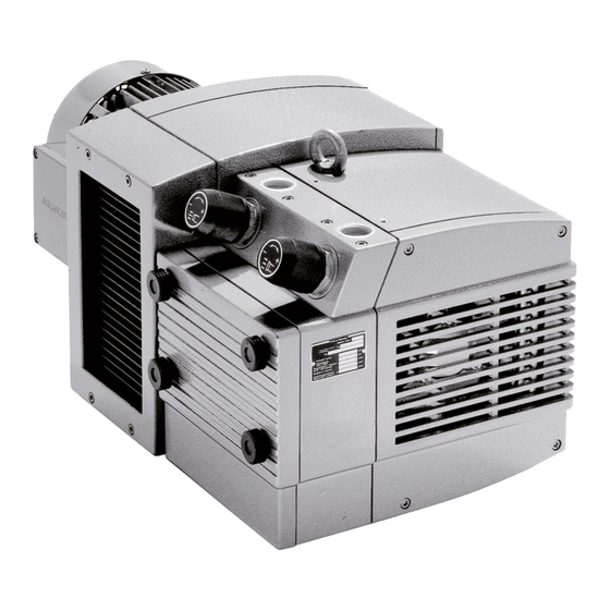
Rotary vane vacuum pumps/compressors,
oilfree running, air-cooled
Contact Gebrüder Becker prior to installation
under noise insulation canopies.
Ambient temperatures must not exceed 45°C.
Connection and installation
Ensure correct dimensions (see Table) and clean
pipelines. Keep connections free from oil, grease,
water and any other contamination. With pipeli-
nes exceeding 5 m in length we recommend the
installation of non-return valves.
Keep connections free from oil, grease, water
and other contaminants.
Remove end caps at DA and SA. Do not connect
to pipeline yet.
Motor connection
Connect the radial compressor to the electricity supply
observing all applicable safety regulations. Comply with
EN 60204 T1.
Connect motor based on connecting diagram (in termi-
nal box) or ready-made plugs. This work should be car-
ried out by an experienced electrician only. Check for
connecting voltage and frequency.
Install motor circuit-breaker with Main switch and
set to nominal motor current. (For data see motor
rating plate).
Avoid switching of more than 10 times per hour.
Briefly start motor and check rotation
(arrow on casing). Exchange phases if rotation is
incorrect.
Commissioning
Connect pressure line at DA and inlet line at SA.
Set vacuum control valve VR or pressure control valve
DR to operating values (for values see table).
sales@combinedfluidproducts.com
Operating Instructions
Do not operate the compressor without safety
equipment against excessive pressure (for maxi-
mum values see rating plate). In case of permit-
ted compression end pressures of more than 1
bar additionally connect a pressure meter and
mark end pressure.
Maintenance
Maintain pump regularly to achieve the best ope-
rating results. Maintenance intervals will depend
on the pump´s use and ambient conditions.
Before commencing maintenance, remove
mains plug from socket to avoid unintentional restarting.
Air compression will generate high tem-
peratures at the compressors: Allow the pump
parts to cool before disassembly.
The filter cartridges are inserted behind the
enclosure cover GD. Clean depending on dust accumu-
lation. Blow out filter from inside to outside.
Replace blocked, oily or greasy cartridges.
Additional filters are available for operation in very dusty
environment.
Blow out dirt in cooling air channels KK by
compressed air.
The vanes are subject to wear due to abrasion from
the walls of the enclosure.
Check vane width every 3000 operating
hours or annually (for minimum widths see Table).
Remove side cover SD for this.
On replacement blow out enclosure by dry compressed
air.
● Vacuum and Compressed Air Specialists ● Since 1975
● Online Orders/Parts:
www.CFPWarehouse.com
Replace the grease loss in the rolling bearing due
to disassembly - 2g 'Amblygon 15/2' grease in
total.Grease is to be found behind GB or with
included grease gun.
DVT/KVT/KDT3.60-3.80:The roller bearings are
prelubricated for life and will not require mainten-
ance.
DVT/KVT/KDT3.100-3.140:Grease Roller bearings
at A and B after 2,000 hours of operation at both
of the grease nippels while the compressor is
running (3.100: 5g and 3.140: 7g).
Replace by original roller bearings only.
Repairing
Please return to Gebr. Becker.
D V T / KVT / KDT 3.60-3.80-3.100-3.140
● Web:
www.combinedfluidproducts.com
Advertisement
Table of Contents

Related Manuals for Becker DVT 3.60


Summary of Contents for Becker DVT 3.60
-
Page 1: Operating Instructions
Vacuum pumps • Compressors oilfree running, air-cooled Application These operating instructions apply to: Contact Gebrüder Becker prior to installation Do not operate the compressor without safety Replace the grease loss in the rolling bearing due -Pressure vacuum pumps DVT 3.60-3.140 under noise insulation canopies. - Page 2 Tabelle-Table-Tableau-Tabella-Tabla DVT/KVT/KDT ..3.60 ..3.80 ..3.100 ..3.140 Anschlußleitung bis 2m / 2m bis 10m . . .1" / 1 1/2" ..1" / 1 1/2" ..1 1/2" / 2" ..1 1/2" / 2" Pipework up to 2m / 2m up to 10m Tuyauterie jusqu’à...
Need help?
Do you have a question about the DVT 3.60 and is the answer not in the manual?
Questions and answers