Table of Contents
Advertisement
Contents
Fast Start .............................................................................................................1
Before Reading This Manual.......................................................................iv
Chapter 1
Introduction.....................................................................1-1
Introduction to DSP.........................................................................................1-2
Product Overview .............................................................................................1-3
Block Diagram ...................................................................................................1-4
Front Panel Layout...........................................................................................1-5
Back Panel Layout............................................................................................1-6
Filter Specifications .........................................................................................1-7
Unit Specifications............................................................................................1-8
General Specifications ...........................................................................1-8
Input/Output Specifications................................................................1-8
Chapter 2
Installation .......................................................................2-1
Back Panel Connections ...............................................................................2-2
Basic Connections ...........................................................................................2-3
Setting Receive Audio Level (Input Level)......................................2-4
Increasing Headphone Audio Level..................................................2-4
Passing Sidetone ..............................................................................................2-5
T/R Connection........................................................................................2-5
CW Sidetone Filter ..................................................................................2-6
DSP to TNC Connections..............................................................................2-6
Chapter 3
Operation..........................................................................3-1
Initial Operation..................................................................................................3-2
CW Operation............................................................................................3-3
SSB (and other voice modes) Operation.......................................3-4
Front Panel Description ................................................................................3-6
PWR LED .....................................................................................................3-6
Input Level LED..........................................................................................3-6
AGC Button .................................................................................................3-7
Program Button .......................................................................................3-7
Memory Button.........................................................................................3-8
Filters Switch..............................................................................................3-8
Tunable Filters Controls........................................................................3-9
Manual Notch Button.............................................................................3-10
MFJ-784B Instruction Manual
i
Advertisement
Table of Contents

Related Manuals for MFJ MFJ-784B


Summary of Contents for MFJ MFJ-784B
-
Page 1: Table Of Contents
MFJ-784B Instruction Manual Contents Fast Start ......................1 Before Reading This Manual...............iv Chapter 1 Introduction..............1-1 Introduction to DSP..................1-2 Product Overview .....................1-3 Block Diagram ....................1-4 Front Panel Layout...................1-5 Back Panel Layout....................1-6 Filter Specifications ..................1-7 Unit Specifications....................1-8 General Specifications ................1-8 Input/Output Specifications..............1-8 Chapter 2 Installation ...............2-1... - Page 2 MFJ-784B Instruction Manual Auto Notch Button ..................3-11 Noise Reduction Control...............3-12 Noise Reduction Button................3-12 Volume Control ..................3-12 Speaker Button ..................3-12 DSP Button ....................3-13 Power Button.....................3-13 Chapter 4 Advanced Features ............4-1 Memory Filters ....................4-2 Saving Memory Filters................4-2 CW Spotting Tone....................4-4 Measuring Frequency ................4-4 Talk ..........................4-5...
- Page 3 MFJ-784B Instruction Manual Appendix A ....................A-1 Self-Test ........................A-2 In Case of Difficulty...................A-4 Technical Assistance..................A-4 MFJ Pre-wired Cables and Open End Cables ........A-5 Pre-Set and Memory Filters Settings Chart ........A-6...
-
Page 4: Before Reading This Manual
Detailed description of the unit and its operation are described in these chapters. The first chapter is an introduction to DSP and the MFJ-784B. The second chapter tells about the back panel and how to install the unit with a radio or TNC. - Page 5 MFJ-784B Instruction Manual...
- Page 7 Fast Start Beginners' Installation and Operation To install and use the MFJ-784B in the simplest way possible, follow the steps below. On some steps we give you a choice of CW or SSB. Choose one throughout this Fast Start section. SSB also works with AM and FM voice.
- Page 8 Experiment with different filter adjustments and functions under various conditions to become familiar with the various controls. 7. Now that you have used the DSP filter you can read other parts of this manual to learn to use the other features of the MFJ-784B. Fast Start 2...
-
Page 9: Introduction
MFJ-784B Instruction Manual Introduction Contents of This Chapter > Introduction to DSP Page 1-2 > Product Overview Page 1-3 > Block Diagram Page 1-4 > Front Panel Layout Page 1-5 > Back Panel Layout Page 1-6 > Filter Specifications Page 1-7 >... -
Page 10: Introduction To Dsp
Analog Device's 16-bit 12 MHz processor, the ADSP-2105, is used in the MFJ-784B. The MFJ-784B DSP Filter converts the analog audio signals from your receiver to digital information. -
Page 11: Product Overview
MFJ-784B Instruction Manual Product Overview The MFJ-784B tunable DSP filter is a highly selective audio filter suitable for most amateur applications. The MFJ-784B contains 5 tunable filters, 5 pre- set filters, a tunable manual notch, an automatic notch filter, and an adaptive noise reduction filter. -
Page 12: Block Diagram
MFJ-784B Instruction Manual Block Diagram Introduction Error! Main Document Only.-4... -
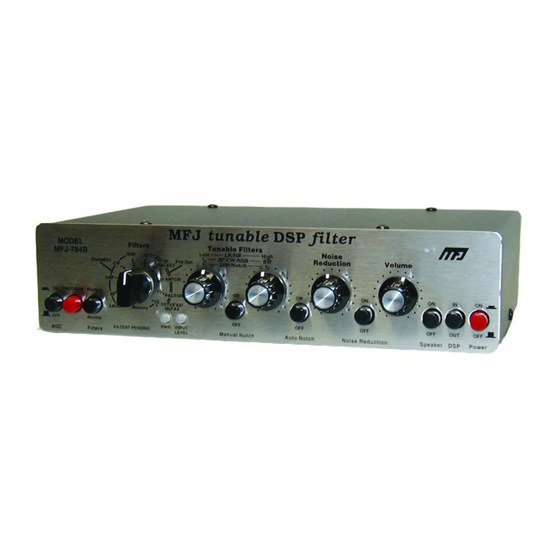
Page 13: Front Panel Layout
MFJ-784B Instruction Manual Front Panel Layout AGC button: Enables the automatic gain control. Program button: Press to program memory filters, to talk, or to activate CW spotting tone. Memory button: Selects either normal or memory filters. Filters switch: Selects one of ten normal or memory filters. -
Page 14: Back Panel Layout
MFJ-784B Instruction Manual Back Panel Layout Power: 10-16 Vdc @ .5 amp peak (low "Z " audio load) Headphones Out: 1/4" stereo or mono phone jack Speaker Out: 3.5 mm stereo or mono phone jack Filtered Audio Adjust: screwdriver adjustable potentiometer Filtered Audio Out: RCA phono jack (~1.5 V P-P @ 600 ohms) -
Page 15: Filter Specifications
MFJ-784B Instruction Manual Filter Specifications Attenuation 7 Type 8 Filter Left Control Right Control LR/HR 1 LR: 200-2200 Hz HR: 1400-3400 Hz 57 dB @ 75 Hz fc: 300-3400 Hz 30-2100 Hz 47 dB @ 60 Hz 2BP 2 f1: 300-3400 Hz... - Page 16 MFJ-784B Instruction Manual FIR - Finite Impulse Response IIR - Infinite Impulse Response LMS - Least Mean Square Introduction Error! Main Document Only.-8...
-
Page 17: Unit Specifications
General Specifications Processor: Analog Devices ADSP-2105. Data width - 16 bits. Clock speed - 12 MHz. Bypass: The MFJ-784B DSP filter has a direct audio bypass when power switch is in "off" position. Input/Output Specifications Power: The maximum current demand will be less than 500 mA at maximum volume but will always be more than 175 mA. -
Page 19: Installation
MFJ-784B Instruction Manual Installation Contents of This Chapter > Back Panel Connections Page 2-2 > Basic Connections Page 2-3 Setting Receive Audio Level (Input Level) Page 2-4 Increasing Headphone Audio Level Page 2-4 > Passing Sidetone Page 2-5 T/R Connection... -
Page 20: Back Panel Connections
Power: This connector supplies power to the unit. It connects to a 2.1 mm coaxial plug with the center conductor positive and the shield ground. An optional dc supply, the MFJ-1315, is available from MFJ. The voltage should be 10-16 Vdc. If the power supply voltage drops below 10 volts the MFJ-784B will perform erratically. -
Page 21: Basic Connections
MFJ-784B Instruction Manual Basic Connections In the most simple case, the MFJ-784B will be installed in the audio path between your receiver and your headphones or speaker. Installation Error! Main Document Only.-3... -
Page 22: Setting Receive Audio Level (Input Level)
Increasing Headphone Audio Level The MFJ-784B headphone level is attenuated as it comes from the factory. If the speaker audio is at a comfortable level and the headphone audio is too quiet, the headphone volume can be raised by using jumpers JMP 9 and JMP 10 (next to the headphones jack). -
Page 23: Passing Sidetone
MFJ-784B Instruction Manual Passing Sidetone You may perfer to listen to a station with different pitch than the sidetone of your transmitter. In this situation, the DSP filter will attenuate the sidetone and you will not be able to monitor your sending. There are two methods of passing sidetone through the DSP filter. -
Page 24: Cw Sidetone Filter
50 Hz. DSP to TNC Connections When connecting to a TNC, MFJ suggests the use of the 5-pin ports. TNCs need a PTT connection that is only available on these ports. The MFJ-784B plugs directly into any MFJ/TAPR2 compatible TNC. Use a 5- pin DIN-to-5-pin DIN cable, MFJ-5100, for connection to MFJ/TAPR2 compatible TNCs or the PK-12/96/900. - Page 25 MFJ-784B Instruction Manual Installation Error! Main Document Only.-7...
-
Page 27: Operation
MFJ-784B Instruction Manual Operation Contents of This Chapter > Initial Operation Page 3-2 CW Operation Page 3-3 SSB (and other voice modes) Operation Page 3-4 > Front Panel Description Page 3-6 PWR LED Page 3-6 Input Level LED Page 3-6... - Page 28 MFJ-784B Instruction Manual Initial Operation Connect the MFJ-784B as outlined in Chapter 2. To prepare the unit, set the controls as follows: Control Position Meaning AGC button: AGC off Program button: Memory button: out (normal) Tunable/Pre-Set mode Filters switch: CW filter...
-
Page 29: Cw Operation
DSP controls (be sure you have read the preceding sections). Your MFJ-784B should be set up as outlined in the initial operation section on the preceding page. Tune in a CW station and adjust your receiver for normal comfortable levels of pitch and volume. -
Page 30: Ssb (And Other Voice Modes) Operation
MFJ-784B Instruction Manual 4. Place the DSP button in the "out" position. Tune your receiver until a frequency is found with several CW signals sending at the same time. When the digital processing is activated by pressing the DSP button "in,"... - Page 31 MFJ-784B Instruction Manual You should notice the signal becomes clearer (less noise and QRM) as the bandwidth (right Tunable Filters control) is moved clockwise and the center frequency (left Tunable Filters control) is re-adjusted. At some point decreasing the bandwidth will make the signal less intelligible. If this happens turn the right Tunable Filters control counter-clockwise.
-
Page 32: Front Panel Description
MFJ-784B Instruction Manual Front Panel Description The following section will help you become familiar with the operation of the DSP. The two LEDs are explained first. The buttons, switch, and controls are then explained from left to right as they appear on the panel. -
Page 33: Agc Button
MFJ-784B Instruction Manual The function of this LED is very simple. When you are listening to a normal signal, the LED should light the most steady and brightest green possible without ever going red. If the LED doesn't light consistently green or lights red on normal signals, the receiver volume or the DSP's Receive Audio Adjust is out of adjustment for the optimum filter performance. -
Page 34: Memory Button
MFJ-784B Instruction Manual Memory Button This button allows you to choose two different groups of filters with the Filters switch. This button functions any time the DSP's power is on and the DSP button is "in." With the Memory button "out," the Filters switch picks one of ten Tunable (front panel adjustable) and Pre-Set (jumper or factory programmed) filters marked LR/HR through SSTV/FAX/WeFAX. -
Page 35: Tunable Filters Controls
MFJ-784B Instruction Manual Tunable Filters Controls The Tunable Filters knobs, left and right, adjust the center frequency (also called the tone or pitch) and the bandwidth (also called the selectivity ) or the lower and upper cutoff frequencies of the 5 Tunable filters selected by the Filters switch. -
Page 36: Manual Notch Button
Tunable Filters left and right knobs to adjust the notch frequencies, you must select and adjust the correct main filter before using the manual notch. The MFJ-784B always "remembers" the Tunable Filters left and right knobs settings when the manual notch is engaged and then the Tunable Filters left and right knobs will only adjust the two manual notch frequencies. -
Page 37: Auto Notch Button
The auto notch operates only in the LR/HR, BP, 2BP, and SSB filters regardless of whether they are saved in memory or not. With the Auto Notch button "in," the MFJ-784B searches for heterodynes or steady tones and instantly removes them. It is so good it can remove four drifting tones at the same time, even if the tones are moving in different directions. -
Page 38: Noise Reduction Control
MFJ-784B Instruction Manual Noise Reduction Control This knob controls how much the noise reduction program reduces random noises. Random noises are noises that do not repeat at exactly the same rate. When this control is in the full clockwise position, random noises are reduced the maximum amount possible. -
Page 39: Dsp Button
MFJ-784B Instruction Manual DSP Button While "in" this button causes the DSP to digitally process the signal. While "out" this button prevents the DSP from doing any digital processing. It operates in any position of the Memory button. Non-processed audio is still available at all the audio outputs when this button is in the "out"... -
Page 41: Advanced Features
MFJ-784B Instruction Manual Advanced Features Contents of This Chapter > Memory Filters Page 4-2 Saving Memory Filters Page 4-2 > CW Spotting Tone Page 4-4 Measuring Frequency Page 4-4 > Talk Page 4-5 Talk Operation Page 4-5 > Jumper Settings... -
Page 42: Memory Filters
MFJ-784B Instruction Manual Memory Filters The MFJ-784B allows you to save your favorite filter settings into one of ten "memory filters" in non-volatile memory. Whenever you have to repeatedly set your DSP filter for similar operating conditions, you may choose to save the settings in memory. - Page 43 MFJ-784B Instruction Manual Press and lock the Memory button in. The PWR LED will now turn green, indicating the memory filters, and your new filter settings will be saved temporarily until they are saved into a memory position (1-10). Note: From steps 2-4 your filter may not appear to work because the filter position (1-10) is still set to the old memory filter.
-
Page 44: Cw Spotting Tone
MFJ-784B Instruction Manual CW Spotting Tone To help you find the center frequency for the CW filter, the MFJ-784B is equipped with a CW spotting tone. The spotting tone marks the center frequency of the tunable CW filter but will not work in a memory CW filter. -
Page 45: Talk
MFJ-784B Instruction Manual Talk In order to know more about the settings of the various filters, MFJ has provided the Talk function. Talk tells you filter settings by sending them over the audio outputs and by flashing them on the LEDs in Morse code. This... - Page 46 Assume the Auto Notch aggressiveness is jumper-set to level 3 Release the DSP button "out". Momentarily press the Program button. The MFJ-784B would send the following Morse Code message: BP CF 1025 BW 350 AN 3 NR 5 This means in memory position 3 you saved a band-pass filter with a bandwidth of 350 Hz and center frequency of 1025 Hz.
- Page 47 On with control midrange: (when off, NR is not sent) * The digital filter cannot exceed the MFJ-784B design frequency range of 0-3900 Hz or 175 Hz minimum bandwidth in SSB. See the Limited Filters section in Chapter 5. Please remember the analog circuitry begins to roll off at 250 and 3100 Hz.
-
Page 48: Jumper Settings
MFJ-784B Instruction Manual Jumper Settings Several features of the MFJ-784B are controlled by internal, movable jumpers. These jumpers are used for: Talk: sets CW tone frequency and Morse code speed Auto Notch: sets aggressiveness level CW sidetone: enables and sets sidetone filter... -
Page 49: Normal Jumper Settings Chart
MFJ-784B Instruction Manual Normal Jumper Settings Chart Tone Frequency 300 Hz 400 Hz 500 Hz 600 Hz *700 Hz 800 Hz 900 Hz 1000 Hz Code Speed *5 wpm 10 wpm 20 wpm 30 wpm Auto Notch Level * Factory defaults. -
Page 50: Setting The Cw Sidetone Filter
MFJ-784B Instruction Manual Setting the CW Sidetone Filter If you do not have a T/R connection and wish to pass CW sidetone through the DSP, you must enable this filter. This is not the preferred method to pass sidetone, see page 2-5. The CW sidetone filter is a jumper programmable internal constant frequency filter. -
Page 51: Pre-Set Filters
MFJ-784B Instruction Manual Pre-Set Filters We have set the RTTY, HF Packet, AMTOR, and PacTOR filters to the most commonly used mark-space frequencies and baud rates. If you wish to change from the factory defaults, you must change the jumpers and program a filter. -
Page 52: Data Mode Jumper Settings Chart
MFJ-784B Instruction Manual Data Mode Jumper Settings Chart Mark-Space (Shift) 1215-1385 Hz (170) 1275-1445 Hz (170) 1415-1585 Hz (170) 1615-1785 Hz (170) *2125-2295 Hz (170) 1200-1400 Hz (200) 1260-1460 Hz (200) 1430-1630 Hz (200) 1600-1800 Hz (200) 2025-2225 Hz (200) -
Page 53: Filter Description
MFJ-784B Instruction Manual Filter Description Contents of This Chapter > LR/HR Filter [1] Page 5-2 Band-stop Filter Page 5-3 > BP Filter [2] Page 5-4 > 2BP Filter [3] Page 5-5 > CW Filter [4] Page 5-6 CW Sidetone Filter Page 5-6 >... -
Page 54: Lr/Hr Filter [1]
MFJ-784B Instruction Manual The following section describes the filters available in the various Filters switch positions in detail. All graphs of the following filters show a line at the noise floor of -55 dB. The response for these digital filters is typically much deeper than -55 dB but circuit noise will generally mask any response below that point. -
Page 55: Band-Stop Filter
MFJ-784B Instruction Manual Band-stop Filter Use: Rejecting broad or variable frequency signals between 1400-2200 Hz. Removes medium to wide frequency width. When the low reject filter, the Tunable Filters left knob, is adjusted to a frequency higher than the high reject filter, the Tunable Filters right knob, the filter removes all frequencies between the two filter settings and passes all frequencies outside the settings of the two filters. -
Page 56: Bp Filter [2]
MFJ-784B Instruction Manual BP Filter [2] Use: Custom Voice, FSK, Custom CW Filter. Passes narrow to wide frequency width. This filter is an adjustable band-pass filter. The bandwidth (BW) is controlled by the Tunable Filters right knob. This adjustment is similar to the selectivity control on a receiver. -
Page 57: 2Bp Filter [3]
MFJ-784B Instruction Manual 2BP Filter [3] Use: Custom Voice, FSK, Dual Pitch CW Filter. Passes 2 independent narrow to wide frequency ranges. This position allows the use of two frequency-independent variable band-pass filters in parallel. The Tunable Filters left and right knobs control the individual center frequencies (f1 &... -
Page 58: Cw Filter [4]
MFJ-784B Instruction Manual CW Filter [4] Use: CW Filter, Narrow FSK. Passes "razor sharp" to medium frequency width. The CW filter is an adjustable band-pass filter that can be varied over the normal frequency range preferred by most CW enthusiasts. -
Page 59: Ssb Filter [5]
MFJ-784B Instruction Manual SSB Filter [5] Use: All Voice modes, FSK, CW Filter. Passes medium to wide frequency width. The SSB filter is a band-pass filter with adjustable center frequency and bandwidth. The center frequency (fc) is adjusted with the Tunable Filters left knob in a range of 600 Hz to 1700 Hz. -
Page 60: Amtor Filter [8]
MFJ-784B Instruction Manual AMTOR Filter [8] Use: AMTOR, Narrow PACTOR, Wide RTTY, FSK. Passes high frequency tones with narrow frequency width. The AMTOR filter is factory pre-set for best performance with standard 2125- 2295 Hz mark-space frequencies (170 Hz shift), 100 baud AMTOR signals. -
Page 61: Manual Notch Filter
MFJ-784B Instruction Manual Manual Notch Filter Use: Removes unwanted tones or heterodynes. Removes up to 2 very narrow frequency ranges and passes all others. The manual notch filter allows the use of two frequency-independent manually tunable notch filters. The Tunable Filters left and right knobs control the individual notch frequencies (f1 &... -
Page 62: Automatic Notch Filter
MFJ-784B Instruction Manual Automatic Notch Filter Use: Removes multiple tones or heterodynes quickly. Removes up to 4 changing tones in the presence of speech signals. The multiple automatic notch filter searches for and eliminates up to four changing or shifting tones in milli-seconds, with attenuation as great as 50 dB. -
Page 63: Limited Filters
MFJ-784B Instruction Manual Limited Filters Filter response is limited to the frequency range of 0-3900 Hz or 175 Hz minimum in SSB mode. When a filter's center frequency setting is low or high enough that the bandwidth would exceed these frequency ranges, the filter is "limited."... -
Page 64: Overlapped Filters
MFJ-784B Instruction Manual Overlapped Filters When the passbands of two filters touch each other, the filters are said to be "overlapped." The result is a single band-pass filter capable of passing all the frequencies of the two individual filters. The filter actually changes its center frequency and bandwidth settings so that the two individual filters are effectively implemented as a single filter. -
Page 65: Appendix A
Contents of This Appendix > Self-Test Page A-2 > In Case of Difficulty Page A-4 > Technical Assistance Page A-4 > MFJ Pre-wired Cables and Open End Cables Page A-5 > Pre-Set and Memory Filters Settings Chart Page A-6 Appendix A-1... -
Page 66: Self-Test
MFJ-784B Instruction Manual Self-Test This self-test is used to test all the digital circuitry, switches, and controls of the MFJ-784B. To perform the self-test: Turn the Filters switch to BP. Push all buttons so they are in the "out" position. - Page 67 MFJ-784B Instruction Manual 16. Test the T/R line by shorting pin 5 of the To Radio connector to ground for approximately one second or until the LEDs blink. If it is shorted for less than one second, the DSP might signal a false failure.
-
Page 68: In Case Of Difficulty
You can also send questions by mail to MFJ Enterprises, INC., PO. Box 494, Mississippi State, MS 39762; by FAX to 601-323-6551 or on Compuserve at 76206.1763@Compuserve.com. -
Page 69: Mfj Pre-Wired Cables And Open End Cables
MFJ-784B Instruction Manual MFJ Pre-wired Cables and Open End Cables The following MFJ radio-to-TNC cables are pre-wired for most 8-pin rigs and HTs. The open end cables allow you to make your own cables. For your nearest dealer or to order call toll-free 800-647-1800. -
Page 70: Pre-Set And Memory Filters Settings Chart
MFJ-784B Instruction Manual Pre-Set and Memory Filters Settings Chart Copy this chart and use it to record your Pre-Set and memory filters settings. Use the Talk function to get the frequency values for CF, BW, and/or LR-HR. Pre-Set RTTY Mode... - Page 71 MFJ-784B Instruction Manual Pre-Set and Memory Filters Settings Chart Copy this chart and use it to record your Pre-Set and memory filters settings. Use the Talk function to get the frequency values for CF, BW, and/or LR-HR. Pre-Set RTTY Mode...
- Page 72 MFJ-784B Instruction Manual Pre-Set and Memory Filters Settings Chart Copy this chart and use it to record your Pre-Set and memory filters settings. Use the Talk function to get the frequency values for CF, BW, and/or LR-HR. Pre-Set RTTY Mode...
- Page 73 MFJ-784B Instruction Manual NOTES Appendix A-9...
- Page 74 MFJ-784B Instruction Manual NOTES Appendix A-10...
Need help?
Do you have a question about the MFJ-784B and is the answer not in the manual?
Questions and answers