Table of Contents
Advertisement
Advertisement
Table of Contents

Related Manuals for MFJ 8100K


Summary of Contents for MFJ 8100K
-
Page 2: Table Of Contents
Receiver Features ...................... 2 Introduction No. 1: For Radio Beginners ..............3 Introduction No. 1: For Experienced Hams, Enthusiasts or Engineers....6 Schematic Diagram of MFJ-8100 ................8 Receiver Controls and Connectors ................9 Understanding and Using the Regeneration Control..........11 Tuning SSB (Single Sideband) Voice Signals ............ -
Page 3: Receiver Features
UNASSEMBLED for credit or refund. If you have never built an electronics kit before, PLEASE study this book carefully before unpacking the small parts. Once you have begun soldering parts, neither MFJ or any dealer can accept the return of the kit for any reason whatsoever. -
Page 4: Introduction No. 1: For Radio Beginners
Before you start building however, please read the notice on page 2 so that there is no misunderstanding about your rights as a valued MFJ customer. Just a Bit of History . . . - Page 5 Back to Today . . . and the Future! Your MFJ-8100 is a much better receiver than the "classic'' radio sets which attracted several generations of Americans to the excitement of radio and electronics. In fact, its basic performance is superior to many of the simplest superhet receivers which were considered such a great step beyond one's first regenerative set.
- Page 6 RF going back out to the antenna. Again, we hope you'll also look at the somewhat more technical explanation of how your MFJ-8100 Receiver circuit works. If any terminology used in this book is unfamiliar to you, please check the "Some Helpful Word & Abbreviations" section.
-
Page 7: Introduction No. 1: For Experienced Hams, Enthusiasts Or Engineers
Why use a REGENERATIVE circuit for a kit new for the 1990's? A fair question, but the MFJ-8100 is not like any regenerative HF receiver you've ever used before! Our GOAL determined the design and circuitry of this receiver. We wanted the following features: •... - Page 8 The result, we think, is a receiver design which bridges the classic simplicity of regeneration to the performance demands of the 1990's. Here's how we did it: In brief, the circuit uses RF regeneration and high levels of DC feedback. Notice that the antenna is coupled directly to the source of RF amplifier FET Q3 rather than through the L-C tuning network.
-
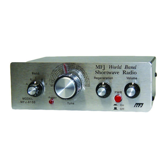
Page 10: Receiver Controls And Connectors
Receiver Controls and Connections Most of the controls are self explanatory. However, it is very important to understand the correct use of the Regeneration Control and the two internal trimmer adjustments of the receiver. BANDSWITCH (SW1) This quality rotary switch selects any one of the 5 tuning ranges from A to E indicated on the tuning scale. - Page 11 DIAL CALIBRATION TRIMMER (C5) This one-time internal adjustment is made with a miniature screwdriver in order to assure that the frequency markings on the front panel are as accurate as reasonably possible. EARPHONE JACKS (J2,J3) These two jacks accept 1/8'' (3.5 mm.) stereo plugs as used in "Walkman'' type headphones or mini-speaker systems.
-
Page 12: Understanding And Using The Regeneration Control
Understanding and Using the Regeneration Control In theory, your receiver's Regeneration Control adjusts the level of feedback or self- oscillation of the FET detector section (Q1 and Q2). In practice, this control is like a "joystick'' for managing and optimizing receiver performance. Your ability to handle this "joystick'' saves you many dollars over today's cost of receivers which perform similar functions "automatically.'' In fact, you might even get more control over receiver performance in varying situations than may be possible with more elaborate receivers. -
Page 13: Tuning Ssb (Single Sideband) Voice Signals
Tuning SSB (Single Sideband) Voice Signals SSB signals are all those voice signals which sound like Donald Duck unless they are tuned in very exactly. They have no background carrier as do AM broadcast signals. On modern ham radio transceivers, tuning SSB is made so easy by means of internal filters that many licensed ham operators are not aware of the basic technique for tuning in SSB signals on receivers without such filters. -
Page 14: Some Helpful Terms And Abbreviations
Some Helpful Words and Abbreviations Throughout this instruction manual, we use plain English as mush as possible. But there's no way around using common electronics terms and abbreviations where appropriate. We simply try to avoid "jargon" that is unnecessary. The following mini- glossary was compiled as a help to beginners working on this kit. - Page 15 Install: in modern kit building, this ward means 1. Select correct part 2. Insert it in its circuit board position, close to the board, oriented correctly. 3. Solder all points 4. Trim or nip away excess wire lengths K: abbreviation for 1000 ohms. (10K = 10,000 ohms). KHz: KiloHertz, a thousand hertz MHz: MegaHertz, a million hertz Inductor: A coil or loop or wire used in electronic circuits.
-
Page 16: Mfj-8100 Parts List
MFJ-8100 Parts Lists Please check and organize your kit parts before soldering. FIXED CAPACITORS 1 - 33pF disc [C6] 1 - 47pF monolithic (marked 47 or 470) [C3] 1 - 75pF disc [C16] 2 - .0033µF polystyrene (rectangular) [C9,C17] 4 - .01µF disc (marked 103Z) [C7,C8,C21,C28] 5 - .1µF DISC (marked 104Z) [C2,C4,C10,C11,C15]... - Page 17 2 - PC-mount 1/8" stereo phone jack [J2,J3] 1 - Insulated binding post (antenna) [J1] 1 - PC-mount push-button switch (DC on/off) [SW2] 1 - 5-position rotary switch (bandswitch) [SW1] HARDWARE & MISCELLANEOUS 1 - Pre-drilled printed circuit board 1 - 9-volt battery snap connector 1 - 9-volt battery bracket with foam adhesive strip 1 - Aluminum chassis (bottom section) 1 - Aluminum cover...
-
Page 19: Before You Start Building
Again before you start soldering, be certain that you understand the MFJ policy on kits explained on page 2 of this book. Once you begin construction, you truly OWN this... -
Page 20: Step-By-Step Kit Construction
STEP-BY-STEP KIT CONSTRUCTION You'll build your receiver in six phases in this order: 1. Small parts associated with bandswitch and tuning 2. Transistor RF amplifier and detector section 3. IC audio amplifier 4. Controls, switches, jacks 5. Testing and initial adjustment 6. -
Page 21: Construction Phase 2 (Steps 2-1 Through 2-20)
Note: The L5 inductor for Band E is a wind-it-yourself "toroidal coil" (don't worry: it's easy!) which we'll make and install in Phase 5 so that it is not subjected to bumping and bending during other assembly. 1-6. Install R4, 10K (brown-black-orange). Its position is between L1 and L2. 1-7. - Page 22 2-8a. The locations for all three FET transistors (Q1, Q2, Q3) are imprinted clearly on the PC board. Notice the flat and rounded sides of the imprints, corresponding exactly to the shape of the transistors viewed from the top. We'll install all 3 transistors in the following steps. (1.) Simply press each one into its 3 holes as far as it can reasonably go, (2.) gently bend the leads outward to secure it, (3.) solder all three connections, and clip away the excess wires.
-
Page 23: Construction Phase 3 (Steps 3-1 Through 3-20)
Construction Phase 3 (Steps 3-1 through 3-20) The following group of parts form the audio amplifier circuit which boosts the signal from the FET transistors to useful listening volume. 3-1a. Examine the 8-pin socket for the LM386 IC and notice the rectangular notch at one end. -
Page 24: Construction Phase 4 (Steps 4-1 Through 4-14)
About the Jumper Wires Several lengths of hookup wire are installed on the top side of the board between points marked W1, W2, etc. The purpose of such "jumper wires" is to make efficient connections across circuit traces on the solder side of the PC board in situations where running a circuit board trace would not be efficient. -
Page 26: Construction Phase 5 (Steps 5-1 Through 5-11)
(Steps 5-1 through 5-11) Testing and Initial Adjustment Congratulations! If you performed Steps 1-1 through 4-13 successfully, your finished MFJ-8100 is already a working shortwave receiver! To be assured of satisfactory receiver performance, PLEASE continue following our step- by-step directions. - Page 27 5-5. Make a temporary connection of your antenna or a 10-20' length of any kind of wire to the short antenna wire near the RF gain control. 5-6. Set the RF Gain trimmer to about 3/4 fully clockwise (as viewed from the rear of the PC board).
-
Page 28: Construction Phase 6 (Steps 6-1 Through 6-18)
Now, use a small screwdriver (or just your finger on the plastic wheel) to adjust trimmer R20 to the point where regeneration just begins, with all other controls set as specified above. (This adjustment will be touched up after the receiver is assembled into its cabinet.) 5-11. - Page 29 6-10. After making sure that everything lines up square and attractively, tighten the three panel nuts, taking great care not to scratch the front panel. 6-11. Turn the Tuning capacitor to the left until the plates are visibly meshed. Press the dial pointer, black washer first, (pointing exactly left) onto the capacitor shaft.
-
Page 30: Dial Calibration Adjustment Of Trimmer Capacitor C5
Note to Hams or Experimenters A very easy method for adjusting C5 is to listen for the MFJ-8100's oscillator on a nearby receiver or transceiver. Even with no antenna wire connected to the MFJ-8100, the oscillator is easily heard within a range of 10-15 feet. -
Page 31: Using And Enjoying Your Receiver
While a single adjustment of C5 can be made using any reference frequency, it's a good idea to use your test equipment or other receiver to verify approximate tuning accuracy on all 5 bands. If one or more bands are drastically wrong, be sure to check for correct inductor values and good solder connections of the inductors. -
Page 32: Setting Up A Useful Shortwave Antenna
Setting Up a Useful Shortwave Antenna The reason why we provided a "universal binding post'' antenna connector (plus separate ground connector) is to make it as easy and economical for you as possible to try out different antenna setups. By "universal,'' we mean that you can insert a "banana''-style plug or make various styles of connection with a simple bare wire. -
Page 33: About The 5 Tuning Ranges Of Your Receiver
specifically designed for headphone operation. If you prefer room-level speaker volume for long listening sessions, we recommend an external amplifier as discussed below. If you use personal FM, cassette or CD players, you probably also know all about those compact "amplified speakers'' designed specifically to plug into the stereo jack of compact personal stereos. -
Page 34: Shortwave Listening In General
The primary purpose of this tuning range is to make it very easy for you to listen to ham radio stations at night on what is known as the 80/75 Meter band. From 3.5 to 3.8 MHz, you'll hear mostly Morse Code signals. From 3.8 to 4.0 MHz, you will hear SSB voice conversations from all around the nation. -
Page 35: In Case Of Difficulty
See the conclusion of this book for information on getting more information! In Case of Difficulty Your receiver is designed to work perfectly as soon as correct construction is completed. Let's review those 5 possible building mistakes which will cause your receiver not work: 1. - Page 36 You can also send questions by mail to MFJ Enterprises, Inc., 300 Industrial Park Road, Starkville, MS 39759; by Facsimile (FAX) to 601-323-6551; or by email to techinfo@mfjenterprises.com.
-
Page 37: Notes For Radio Hams And Experimenters
The author conducted a few simple tests using an HW-9 for transmitting, side by side with the MFJ-8100 on 30, 20, 17 and 15 meters. You will want T-R switching to short the receiver antenna input to ground and also to mute the audio. -
Page 38: Conclusion
As the years go by, we have a hunch that you'll always remember the first thrills of listening to your MFJ-8100. And, because it's rugged, compact, and far more sophisticated than the first receivers of yesteryear, we... -
Page 39: Circuit Component Index
Circuit Component Index Part Number Value/Description Step No. MFJ Part No. Air-variable, tuning 204-5050 .1 uF 2-17 200-2017 47 pF 205-0021 .1 uF 200-2017 5-30 pF trimmer 1-10 204-0013 33 pF 200-2016 .01 uF 200-2015 .01 uF 2-13 200-2015 .0033 polystyrene...
Need help?
Do you have a question about the 8100K and is the answer not in the manual?
Questions and answers