Advertisement
Quick Links
Safety instructions
Electrical equipment may only be installed and
assembled by a qualifi ed electrician. Always
follow the relevant accident prevention regula-
z
tions.
Failure to comply with these installation in-
structions may result in damage to the device,
fi re or other hazards.
When installing and laying cables, always com-
ply with the applicable regulations and stand-
ards for SELV electrical circuits.
These instructions are an integral component
of the product and must be retained by the end
user.
M `
Design and layout of the device
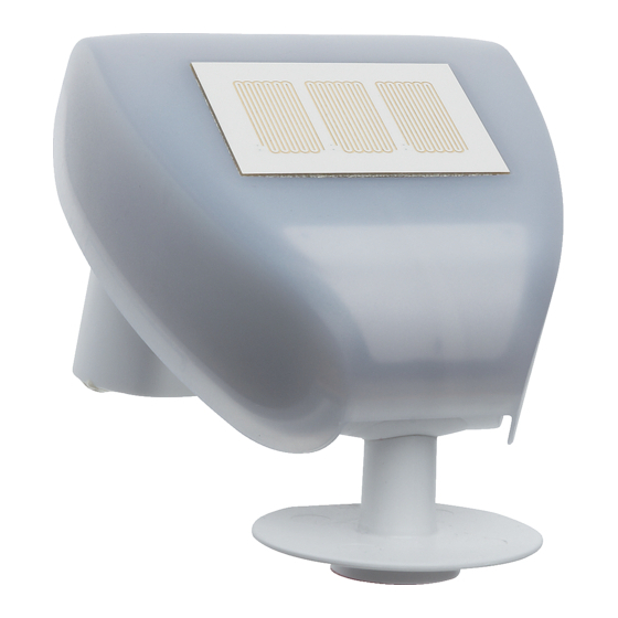
TXE530
Weather station with GPS
(5)
(3)
Figure 1: Exterior view
(1) Precipitation sensor on housing cover
(2) Brightness/twilight sensor
(3) Housing, bottom part
(4) Temperature sensor
(5) Wind sensor
Function
System information
This device is a product of the KNX system and
corresponds to the KNX guidelines. Detailed
specialised knowledge obtained from KNX training
courses
is required for understanding. The planning, instal-
lation and commissioning are carried out with the
help of KNX-certifi ed software.
Systemlink start-up
The function of the device is software-depend-
ent. The software is to be taken from the product
database. You can fi nd the latest version of the
product database, technical descriptions as well as
conversion and additional support programmes on
our website.
Easylink start-up
The function of the device is confi guration-de-
pendent. The confi guration can also be done using
devices developed specially for simple setting and
start-up.
This type of confi guration is only possible with
Information for electricians
z
devices of the easylink system. Easylink stands for
Installation and electrical connection
easy, visually supported start-up. Preconfi gured
standard functions are assigned to the in/outputs
DANGER!
ç
by means of a service module.
Touching live parts in the installation
During Easylink start-up, only one weather
P
environment can result in an electric
station can be confi gured per installation.
shock.
Correct use
The device could get damaged.
- Measurement and evaluation of the weather
Disconnect the connecting cables
data: precipitation, temperature, wind speed,
before working on the device and
twilight and brightness
cover all live parts in the area!
- Horizontal installation on the outside of build-
ings (fi gure 3), preferably in the roof and facade
Selecting installation location
area
Select the assembly location so that wind, precip-
The measured values apply to the installation
P
itation and sun can be detected by the sensors
location. Variations to other weather servic-
without impedance:
es– e.g. through local turbulence or areas with
- Avoid infl uences by obstacles or shadings such
build-ups of air – are possible.
as facades, roofs or trees
(1)
Product characteristics
- Do not install underneath construction compo-
nents that can delay precipitation from reaching
- Integrated KNX bus coupling and data process-
the sensor
ing unit
- Avoid infl uences on the GPS signal caused by
- Integrated GPS antenna
(2)
magnetic fi elds, transmitters and interference
- Direct control of switching outputs via alarm
fi elds for electrical devices, such as fl uorescent
stages: rain alarm, frost alarm, wind alarm in 3
lamps, neon signs and switching power supply
stages – 4, 8 or 12 m/s.
units
- Reception of date, time and location data (in-
- Do not mount in the vicinity of chimneys or oth-
stallation location) via GPS signal
er gas or ventilation systems
- convenient shade and heat protection functions
- Do not mount in the vicinity of radio transmitter
(with position tracking and horizontal sun track-
systems
ing) for up to four building facades through the
- Leave a minimum distance to surfaces below
use of a brightness sensor and accurate solar
the weather station of 60 cm in order to guaran-
positioning calculations
tee correct measurement of wind and in order
By integrating the weather station into the do-
P
to not get snowed in
movea visualisation, you can access enhanced
- Install on vertical walls (fi gure 2) or on a mast
functions such as setpoint settings for con-
(fi gure 5, right)
trolling switching outputs, logic functions and
the timer.
Select the mounting location so that the
P
weather station will always be accessible for
GPS data, date, time
maintenance purposes.
The date, time and exact location coordinates
of the weather station are received via the GPS
signal. Date and time can also be received via
the KNX bus and may be used as master or slave
(4)
depending on ETS programming.
This information is required to control the automat-
90°
ic changeover for daylight savings time.
If programmed, the device receives the date
P
and time during fi rst start-up via the KNX bus
until the fi rst GPS signal is received.
If the device is operated in a country that does
P
not require changes to be made for daylight
savings time, the Summer time offset in minutes
should be set to zero..
Maintaining the device
The weather station should be checked for soiling
at regular intervals – at least twice a year – and
cleaned if necessary.
Heavy soiling can make it impossible to calcu-
P
late wind speed correctly, cause the precipita-
Figure 2
tion sensor (1) to display a permanent precipita-
tion message, or prevent the brightness sensor
Aligning the device
(2) from detecting any sunlight.
To measure the brightness accurately, align the
weather station in such way that the brightness/
Scope of delivery
twilight sensor (2) faces south.
- Weather station
Use a compass to align the device to the south
- Wall/mast fi xing
(fi gure 3).
- Set of screws and dowels for wall mounting
An incorrect alignment may infl uence the meas-
P
- 2 Cable ties for mast assembly
ured values of the brightness sensor..
In some cases, it may be appropriate to align
P
the device in a direction other than south to ac-
commodate existing walls or other geographical
factors.
Use a spirit level to align the device horizontally
(fi gure 3).
N
W
E
(1)
(2)
S
Figure 5: Wall fi xing (left) or mast fi xing (right)
(7) crescent-shaped bar
Figure 3: Aligning the device horizontally and to
face south
Gently pull the cover apart from the detent
mechanisms (9) at the sides and remove the
Connecting and installing the device
cover (8) from the bottom part of the housing
Observe the layout requirements for SELV
P
(3).
installations.
Take care when opening the weather station.
P
To avoid EMC interference, do not install input
P
The precipitation sensor in the cover and the
cables parallel to mains cables.
printed circuit board in the bottom part of the
The weather station is supplied complete with a
housing are connected by a cable.
wall/mast fi xing (6). This is locked into place on the
rear of the device upon delivery (fi gure 4).
Optional holders are available for mounting the
P
device on walls, masts or brackets (see acces-
sories).
Carefully loosen the wall/mast fi xing (6) from
the detent mechanism using a screwdriver and
slide it downwards to remove (fi gure 4).
(6)
Figure 6: Preparation for mounting
(8) Cover with precipitation sensor
(9) Detent mechanisms on the cover
Route the cables from the auxiliary voltage
Figure 4: Loosening the wall/mast fi xing
and KNX bus through the rubber seals on the
(6) Wall/mast fi xing
bottom part of the weather station.
Use two screws to attach the fi xing vertically to
The second wire pair (yellow/white) of the KNX
P
a wall or use the accompanying cable ties to
bus coupling unit may be used for connection of
attach it to a mast.
> 60 cm
auxiliary voltage.
When doing so, please ensure that:
Connect the bus cable via the connecting termi-
nal (11). Be sure that the polarity is correct.
- In the case of wall mounting, the smooth side
lies against the wall and the crescent-shaped
Connect auxiliary voltage to connecting termi-
bar (7) is at the top (fi gure 5, left).
nals (10).
- In the case of mast mounting, the curved side
lies against the mast and the crescent-shaped
bar (7) is at the bottom (fi gure 5, right).
The distance between the holes and the meas-
P
urements for aligning them can be found in the
accompanying drilling plan.
Disconnect bus line (11) and auxiliary voltage
(10)
Start-up
P
(11)
(12)
Systemlink – Loading the physical address and
(13)
application software
The device is mounted and also connected to the
(14)
KNX bus and auxiliary voltage.
(2)
P
(7)
P
Gently pull the cover apart from the detent
Figure 7: Interior view
(10) Connecting terminals for auxiliary voltage
P
(11) KNX bus connection terminal
(12) Connector for precipitation sensor in the
housing cover
(13) Programming button and programming LED
Switch on bus voltage
(14) GPS antenna
Switch on auxiliary voltage.
Place cover (8) onto the bottom part of the
Press programming button (13).
(8)
housing (3) and push carefully until it engages
audibly.
P
Slide the weather station into the mounted
fi xing from above. Ensure that the pins for the
Load the physical address into the device.
wall/mast fi xing engage audibly into the guides
for the bottom part of the housing (fi gure 8).
The weather station is ready for operation.
Load application software Note down the physi-
The wind measured value and all wind
P
switching outputs cannot be outputted until 60
P
seconds after the auxiliary voltage has been
applied.
Place cover (8) onto the bottom part of the
(9)
(3)
Easylink
Information on the system confi guration can be
taken from the extensive description of the service
module easylink.
P
Appendix
Technical data
Figure 8: Installing onto the fi xing
KNX Medium
In the event of any damage, take the device out
P
of operation immediately and safeguard against
Confi guration mode
turning back on.
Rated voltage KNX
Dismantling the device
Dismantling the device
Current consumption KNX
CAUTION!
Connection mode KNX
ç
Opening the device may allow mois-
Auxiliary voltage
ture to enter the interior.
Auxiliary current
This would result in damage to the
electronics.
Do not open the device in the event of
Operating temperature
precipitation and be sure to remove
Operating altitude
any external moisture from the device
Storage/transport temperature
with a dry cloth before attempting to
Conductor cross-section (rigid)
disassemble.
Dimensions (W x H x D)
Pull upwards against the resistance created by
Weight
the detent mechanism to remove the device
Degree of protection
from the wall/mast fi xing from above.
Surge voltage
Gently pull the cover apart from the detent
Overvoltage category
mechanisms (9) at the sides and remove the
cover (8) from the bottom part of the housing
Degree of contamination
(3).
Hager Controls S.A.S., 33 rue Saint-Nicolas, B.P. 10140, 67703 SAVERNE CEDEX, France - www.hager.com
Software
class A
(10).
Action type
Ball test temperature
Precipitation sensor:
The weather station must only be operated from
- Measurement precipitation
Yes/No (1 bit)
its fi xed installation position once all installation
- Heating
approx. 1.2 W
and commissioning work is complete.
Temperature sensor:
- Measuring range
-30 ... +80°C
- Resolution
- Measuring accuracy
± 0,5 °C at +10 ... +50 °C
-
± 1 °C at -10 ... +85 °C
-
± 1,5 °C at -25 ... +150 °C
It is advisable to program the physical address
before installation.
Wind sensor:
The physical address is only ever assigned for
- Measuring range
0 ... 35 m/s
- Resolution
0.1 m/s
one device. Only one device can ever be in
- Measuring accuracy
± 15% of measured value
programming mode.
with an incidental fl ow from 90 ... 270 °
mechanisms (9) at the sides and remove the
Brightness/twilight sensor
cover (8) from the bottom part of the housing
- Cardinal direction
(3).
- Measuring range
0 lx ... 150 klx
Take care when opening the weather station.
- Measuring accuracy
± 20 % at 0 lx ... 10 klx
The precipitation sensor in the cover and the
± 15 % at 10 ... 150 klx
printed circuit board in the bottom part of the
Test mark
KNX, CE
housing are connected by a cable.
Conformity according to EMC Directive 2004/108/
EC, Low Voltage Directive 2006/95/EC
Standards
EN 50491-3
EN 50491- 5 -2: 2011
The programming LED (13) lights up.
EN 60730 - 1: 2011
If the programming LED does not light up, no
Troubleshooting
bus voltage is present.
Bus operation is not possible
The programming LED (13) goes out
Cause 1: Bus voltage is not present.
Check bus connection terminals (11) for correct
cal address on the labelling fi eld.
polarity.
The loading of non-compatible application
Cause 2: Auxiliary voltage is not present.
software is indicated by fl ashing of the program-
ming LED (13)
Check connection for auxiliary voltage (10).
Check auxiliary voltage by means of measuring
housing (3) and push carefully until it engages
device.
audibly.
Auxiliary voltage is also essential for bus opera-
P
The weather station has been commissioned.
tion.
Precipitation sensor is permanently covered in
snowy weather
Cause: Heating does not work. Auxiliary voltage is
not present.
During Easylink start-up, only one weather
Check connection for auxiliary voltage (10).
station can be confi gured per installation.
Check auxiliary voltage by means of measuring
device.
Accessories
KNX power supply
TP 1
320 mA + 24 V DC, 640 mA RMD
TXA114
S-Mode, E-Controller
Power supply fl ush-mounted, 24 V DC
s 30 V SELV
(auxiliary voltage)
TP110
max. 6 mA
Hinge arm,
bus connecting terminal
large, for weather station KNX
TG353
s 12 ... 40 V SELV
Hinge arm,
~ 12 ... 24 V SELV
small, for weather station KNX
TG354
max. 185 mA at 12 V s
max. 80 mA at 24 V s
-30 ... + 50 °C
max. 2000 m
-30 ... +70 °C
max. 0.5 mm
2
ca. 96 x 77 x 118 mm
170 g
IP44
1500 V
III
2
12/2014 - 6LE000400A
type 2
75 °C
0.1 °C
South
Advertisement

Subscribe to Our Youtube Channel
Related Manuals for hager TXE530


Summary of Contents for hager TXE530
- Page 1 Use a spirit level to align the device horizontally start-up. cover (8) from the bottom part of the housing Degree of contamination (fi gure 3). (3). Hager Controls S.A.S., 33 rue Saint-Nicolas, B.P. 10140, 67703 SAVERNE CEDEX, France - www.hager.com 12/2014 - 6LE000400A...
- Page 2 Hager Controls S.A.S., 33 rue Saint-Nicolas, B.P. 10140, 67703 SAVERNE CEDEX, France - www.hager.com 12/2014 - 6LE000400A...
Need help?
Do you have a question about the TXE530 and is the answer not in the manual?
Questions and answers