Advertisement
Quick Links
Owner's Guide
Thank you for purchasing the LinkLITE high precision battery monitor.
Important
Misusing or incorrectly connecting the LinkLITE may damage the equipment.
Read and keep this Owner's Guide and the enclosed Installation Guide.
WARNING: Fire hazard
Do not operate this product unless it has been installed by a qualified
installer, in accordance with applicable codes and the Installation Guide.
WARNING
Do not use LinkLITE in connection with life support systems, medical
equipment, or where human life or medical property may be at stake.
FCC Information
This Class B digital apparatus complies with Canadian ICES-003 and Part 15 of
the FCC Rules. Operation is subject to the following two conditions: (1) this
device may not cause harmful interference, and (2) this device must accept any
interference received, including interference that may cause undesired operation.
NOTE: The Class B limits are designed to provide reasonable protection against
harmful interference in a residential installation.This equipment generates, uses
and can radiate radio frequency energy and, if not installed and used in
accordance with the instructions, may cause harmful interference to radio
communications. However, there is no guarantee that interference will not occur
in a particular installation. If this equipment does cause harmful interference to
radio or television reception, which can be determined by turning the equipment
off and on, the user is encouraged to try to correct the interference by one or more
of the following measures:
• Reorient or relocate the receiving antenna.
• Increase the separation between the equipment and receiver.
• Connect the equipment into an outlet on a circuit different from that to which
the receiver is connected.
• Consult the dealer or an experienced radio/TV technician for help.
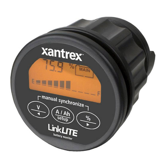
LinkLITE Display and Control Overview
Synchronisation
In order to keep your LinkLITE battery monitor delivering accurate status
information about your battery, it is important to regularly synchronize your
battery monitor with your battery. As explained in the quick start guide, a
synchronisation step is also needed before you can actually use your battery
monitor. During operation, the battery monitor automatically indicates when a
synchronisation is required, by displaying the message SYNCHRONIZE.
A synchronisation step means nothing more than performing a complete charge
cycle on your battery. A charge cycle will be considered complete when both
Auto-sync parameters F02 and F03 are met during at least 4 minutes. This
typically means : when the battery charger switches to float mode. By meeting
these conditions, the battery is considered full, which will be indicated by a
flashing FULL message on the display. Besides this, the State-of-charge readout
will be set to 100% and the Amphour readout reset to 0Ah. The FULL message
will disappear when a key is pressed, or automatically, when the battery starts
discharging again.
Performing synchronisations regularly is also important to keep your battery
healthy and to increase it's lifetime. You will notice that if you are often
performing full charge cycles yourselves, the battery monitor will most likely not
display the SYNCHRONIZE message, since the battery is already kept in good
sync with the battery monitor.
Besides automatic synchronisations based on meeting the Auto-Sync Functions,
you can also manually synchronize the battery monitor with your battery when
you are sure your battery is fully charged. This can be accomplished by pressing
both < and > keys simultaneously for three seconds. After these three seconds,
the flashing FULL message appears on the the display just like when it is
automatically synchronized.
Xantrex and Smart Choice For Power are trademarks of Xantrex International, registered in the U.S. and other countries. Other trademarks, registered trademarks, and product names are the property of
their respective owners and are used herein for identification purposes only. LinkLITE Owner's Guide © June 2008 Xantrex International. All rights reserved.
Unless specifically agreed to in writing, Xantrex Technology Inc. ("Xantrex"): (a) makes no warranty as to the accuracy, sufficiency or suitability of any technical or other information provided in its
This pdf was downloaded from
manuals or other documentation. (b) assumes no responsibility or liability for losses, damages, costs or expenses, whether special, direct, indirect, consequential or incidental, which might arise out of
the use of such information. The use of any such information will be entirely at the user's risk; and (c) reminds you that if this manual is in any language other than English, although steps have been
taken to maintain the accuracy of the translation, the accuracy cannot be guaranteed. Approved Xantrex content is contained with the English language version which is posted at www.xantrex.com.
1. Charge battery indicator
2. Alarm activated indicator
3. Numeric value indicator field
4. Readout units
5. Main battery or Auxiliary battery
indicator
6. State-of-charge bar
7. Synchronize indicator
8. Select State-of-charge readout, or next
value (>)
9. Select current(A) or Amphour(Ah)
readout, or enter / leave Setup menu
10. Select voltage readout (Main or
Auxiliary), or previous value (<)
MarineSupplyDock.com
Setup menu
Using the Setup menu, your battery monitor can be adjusted to fit into your
system. A number of parameters, called Functions, can be set according to your
needs. This menu can be accessed by the following sequence :
[3 sec]
When the Setup menu is entered, you can use the < and > keys to browse through
the different Functions. By pressing the SETUP key, the selected Function value
can be viewed. The < and > keys can now be used to change this value. Pressing
the SETUP key again, will then step back to the Setup menu. From any menu
position, the Normal Operating Mode can be accessed again by pressing the
SETUP key for 3 seconds. This will also save any Function value changes to
internal memory. When no keys are pressed for 90 seconds while operating in the
Setup menu, the battery monitor will automatically return to the Normal
Operating Mode again without saving any Function value changes.
The factory settings are based on a 12V battery system with a capacity of 200Ah.
For 12V systems, generally only Function F01 has to be checked for correct
operation of your battery monitor. When your battery capacity is other than
200Ah, Function F01 has to be changed to a value that is equal to your battery
capacity. All other Functions can be left unchanged if you are uncertain about
adjusting these values yourselves.
When your battery system is 24V, besides checking battery capacity Function
F01 for the correct value, you should also change the values of F02 and F05.
Default 24V system values for F02 and F05 are respectively 26.4V and 21.0V.
The following Functions are available :
Battery capacity. Your Main battery's capacity in Amphours (Ah).
F01
Default: 200Ah
Range: 20 – 999Ah
Charger's float voltage (Auto-sync parameter). This value must be equal to
F02
your battery charger's float voltage. which is the last stage of the charging
process. In this stage the battery is considered full.
Default: 13.2V
Range: 8.0V – 33.0V
Charger's float current (Auto-sync parameter). When the charge current is
F03
below this percentage of the battery capacity (see Function F01), the
battery will be considered as fully charged. Make sure this Function value
is always greater than the minimum current at which the charger maintains
the battery or stops charging.
Default: 2.0%
Range: 0.5 – 10.0%
Low battery alarm On (% SOC). When the State-of-charge percentage has
F04
fallen below this value, the alarm relay will be activated, the Charge
battery indicator starts flashing and the State-of-charge bar is empty.
Default: 50%
Range: 0 – 99%
Low battery alarm On (Volts). When the battery voltage has fallen below
F05
this value, the alarm relay will be activated.
Default: 10.5V
Range: 8.0 – 33.0V
Low battery alarm Off (% SOC). When the State-of-charge percentage has
F06
risen above this value and the alarm relay was activated, the alarm relay
will deactivate again. When "FULL" is selected, the alarm relay is
deactivated when the Auto-sync parameters are met.
Default: 80%
Range: 1 – 100% /FULL Step size: 1%
Peukert's exponent. The Peukert's exponent represents the effect of
F07
reducing battery capacity at higher discharge rates. When the Peukert
value of your battery is unknown, it is recommended to keep this value at
1.25. A value of 1.00 disables the Peukert compensation.
Default: 1.25
Range: 1.00 – 1.50
Shunt Amp Rating. This Function represents the Amp rating of your shunt
F08
at 50mV. Included with your battery monitor is a 500Amp/50mV shunt,
meaning that at 500A flowing through the shunt, a voltage of 50mV is
generated across the small 'Kelvin' screw terminals of the shunt. This
voltage will be used by the battery monitor to measure the amount of
current.
Default: 500A
Range: 10 – 900A
Backlight mode. Represents the duration of backlight activation in seconds
F09
after key-press. The backlight can also be set to be always "ON" or always
"OFF". Function setting "AU", activates the backlight automatically when
charge / discharge current exceeds 1Amp or when a key is pressed.
Default: 30sec
Range: OFF / 5 – 300sec
/ ON / AU
Alarm contact polarity. Enables selection between a normally open (NO)
F10
or normally closed (NC) contact.
Default: NO
Range: NO / NC
Reserved
F11
Default: x
Range: x
Firmware version. Displays the firmware version of the battery monitor
F12
(read only).
Default: x.xx
The last two Functions are called Reset Functions. By pressing the SETUP key
the selected Reset Function can be viewed. The default value for all Reset
Functions is "OFF". To actually reset the selected Function, use the < and > keys
to change the value from "OFF" to "ON". Pressing the SETUP key again, will
step back to the Setup menu. All reset items set to "ON" will only be reset once
Step size: 1Ah
Step size: 0.1V
Step size: 0.1%
Step size: 1%
Step size: 0.1V
Step size: 0.01
Step size: variable
Step size: variable
Advertisement

Subscribe to Our Youtube Channel
Related Manuals for Xantrex LinkLITE

Summary of Contents for Xantrex LinkLITE
-
Page 1: Setup Menu
LinkLITE Owner’s Guide © June 2008 Xantrex International. All rights reserved. Unless specifically agreed to in writing, Xantrex Technology Inc. (“Xantrex”): (a) makes no warranty as to the accuracy, sufficiency or suitability of any technical or other information provided in its This pdf was downloaded from MarineSupplyDock.com... - Page 2 ø 64mm (2.54") Xantrex and Smart Choice For Power ist eine Marke von Xantrex International.. Andere Marken, eingetragene Marken und Produktbezeichnungen sind Eigentum der jeweiligen Eigentümer und werden in WENN NICHT AUSDRÜCKLICH SCHRIFTLICH FESTGELEGT, TRIFFT FOLGENDES AUF XANTREX TECHNOLOGY INC. (IM FOLGENDEN KURZ "XANTREX" GENANNT) ZU. XANTR This pdf was downloaded from MarineSupplyDock.com...
Need help?
Do you have a question about the LinkLITE and is the answer not in the manual?
Questions and answers