
Related Manuals for Hardy Process Solutions HI 6600-EIP

Summary of Contents for Hardy Process Solutions HI 6600-EIP
- Page 1 HI 6600 Series Modular Sensor System User Guide HI 6600 Series Modular Sensor System User’s Guide Hardy Process Solutions Document Number: 0596-0333-01 REV D Page | 1...
- Page 2 HI 6600 Series Modular Sensor System User Guide Local Field Service Hardy Process Solutions provides local field service for all scales and weighing equipment. Hardy’s factory trained technicians can perform service on all Hardy equipment as well as most other manufacturers’...
-
Page 3: Table Of Contents
HI 6600 Series Modular Sensor System User Guide Contents • • • • • • Chapter 1 ............................8 HI 6600 Series Overview ........................ 8 Introduction to the HI 6600 Modular Sensor System.............. 8 Typical Applications ......................10 HI 6600 Series Model Numbers ..................10 Chapter 2 ............................ - Page 4 HI 6600 Series Modular Sensor System User Guide Using the HI 6110 Front Panel Display ..................31 Mode Button ........................32 Channel Identification ....................... 33 System Discovery ......................33 Instrument ID ......................... 34 Channel Identification ....................34 Deleting Channels ......................35 Replace Channel ......................
- Page 5 HI 6600 Series Modular Sensor System User Guide Zero Command ........................ 50 Auto Mode........................50 Count Operations ........................51 Determining Piece Count:....................51 Chapter 6 ............................52 Network Communications ......................... 52 Maximum Number of Channels Supported for PLC Communication Formats ..... 53 LAN Connection ......................
- Page 6 HI 6600 Series Modular Sensor System User Guide Modifying the Read Only Parameters ................... 88 Chapter 8 ............................89 Troubleshooting ..........................89 Assembly Notes, Warnings & Cautions ..................89 Updating Instrument Firmware ................... 90 Information Page ....................... 90 Indicator Lights Summary ....................91 Common Error Messages ......................
- Page 7 HI 6600 Series Modular Sensor System User Guide Portion of the OUTPUT table used for Weigh Processing Modules (WPMs) ..... 122 INPUT Table Description ......................122 Portion of the INPUT table used for the Hardy Gateway Module (HGM) ....122 Portion of the INPUT table used for Weigh Processing Modules (WPMs) ....
-
Page 8: Chapter 1
System. Be sure to read and understand all cautions, warnings, and safety procedures in this manual to ensure safe installation and operation of the instrument. Hardy Process Solutions sincerely appreciates your business. We encourage input about the performance and operation of our products from our customers. Should you not understand any information in this manual or... - Page 9 HI 6600 Series Modular Sensor System User Guide The system is used for front end signal processing of strain-gage type sensors and load cells for all types of industrial and machine weighing applications. Operating blind or with an optional display, the Modular Sensor System conditions, converts and communicates stable processed weight readings from connected load sensors or scales to a variety of control and monitoring systems.
-
Page 10: Typical Applications
HI 6600 Series Model Numbers Model Number Description HI 6600-EIP Hardy Gateway Module - EtherNet/IP HI 6600-PB Hardy Gateway Module - Profibus-DP HI 6610-WP... -
Page 11: Chapter 2
HI 6600 Series Modular Sensor System User Guide Chapter 2 Specifications and Features • • • • • • Chapter 2 provides specifications for HI 6600 series instruments. The specifications listed are designed to assist in the installation, operation and troubleshooting of your instrument. All service personnel should be familiar with this section before installing or repairing the instrument. -
Page 12: Hardy Gateway Module (Hi 6600)
HI 6600 Series Modular Sensor System User Guide Load Sensor Input per WPM Up to four 350-ohm full Wheatstone bridge, strain gauge load sensor/cells (5 volt excitation) can be connected to the weigh scale input on each WPM. Note: Connecting 2 or more load cells requires a summing card or Junction Box. Non-linearity ... -
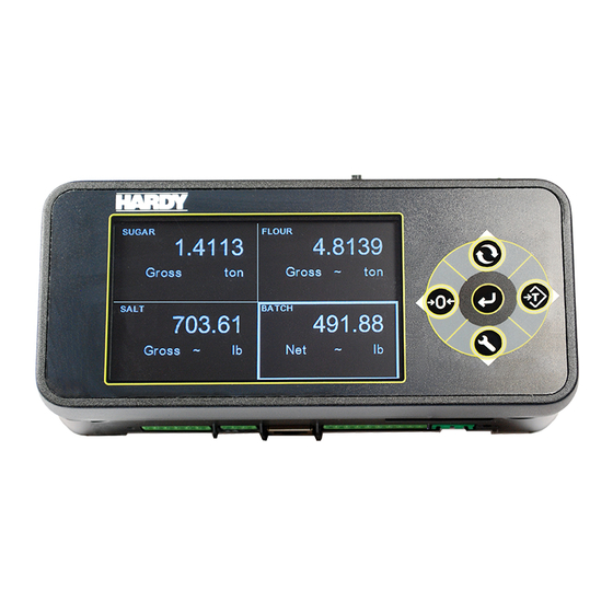
Page 13: Optional Hi 6110 Front Panel Display
A C2 weighing system consists of up to four load cell sensors per WPM, a junction box, interconnect cable, and an instrument with C2 capabilities (e.g., the HI 6600 series instrument). Each Hardy Process Solutions C2-certified load sensor outputs digital information used for calculating the Page | 13... -
Page 14: Integrated Technician
HI 6600 Series Modular Sensor System User Guide calibration. When the HI 6600 series instrument reads the signals from the load sensors, it calibrates the scale based on the load sensor’s output plus a user-supplied reference point value (from 0 to any known weight on the scale). - Page 15 HI 6600 Series Modular Sensor System User Guide Table 1: Maximum number of WPM Units at specific distances without Auxiliary Power To add either distance or the maximum number of units, you will need to apply auxiliary power as shown in the following configuration scenarios.
- Page 16 HI 6600 Series Modular Sensor System User Guide Page | 16...
- Page 17 HI 6600 Series Modular Sensor System User Guide For further information, email Hardy Technical Support at hardysupport@hardysolutions.com or call to discuss your needs with a trained Hardy Service Agent, at 800-821-5831 or 959-278-2910 and select Option 4 (6:30AM to 5:30PM PST). Page | 17...
-
Page 18: Chapter 3
HI 6600 Series Modular Sensor System User Guide Chapter 3 HI 6600 Hardware Installation • • • • • • Chapter 3 covers physical installation of HI 6600 Modular Sensor System. User and service personnel should read this chapter before installing or operating the HI 6600 Modular Sensor System. Safety Before you begin installing your HI 6600 series equipment, please review the important safety precautions below. -
Page 19: Tool List
2) Check to see that everything in the package matches the bill of lading. 3) If items are missing or you have any questions, contact Customer Service at: Hardy Process Solutions 9440 Carroll Park Drive San Diego, CA 92121 Phone: (800) 821-5831... -
Page 20: Overview Of The Hi 6600 Hardware
HI 6600 Series Modular Sensor System User Guide Overview of the HI 6600 Hardware Before installing the HI 6600 Series, familiarize yourself with the basic configuration as shown below. DC Power, Shield, Ports for HardyNet and a Termination switch can be found on the bottom of both the Hardy Gateway Module and the Weight Processing Modules. -
Page 21: Installation
HI 6600 Series Modular Sensor System User Guide Installation The HI 6600 Series WPMs and HGMs are designed to be installed on a DIN rail as shown below. The MAXIMUM span between the first and last module that comprise a system is 500 feet (150 meters). -
Page 22: Cabling The Units Together
HI 6600 Series Modular Sensor System User Guide To remove: 1) Disconnect all wiring on the underside of the module to expose the spring-clip slot. Spring Clip Slot 2) Insert a flat-blade screw driver into spring-clip slot then gently lift up on the screwdriver handle, using the back corner of the module to assist in prying the spring-clip in a downward direction. -
Page 23: Dc Power Input
HI 6600 Series Modular Sensor System User Guide Redundant DC power may also be supplied individually to each Weight Processing Module via the DC power input terminal located on the bottom of the module. DC power supplied to individual Weight Processing Modules is isolated and not distributed to other modules on the system. -
Page 24: Connecting Sensors
HI 6600 Series Modular Sensor System User Guide WARNING - Be careful not to reverse the ground and hot wires, which can result in damage to the equipment. AVERTISSEMENT – Attention à ne pas inverser le sol et fils chauds, ce qui peut entraîner des dommages à... -
Page 25: Installing The Optional Display
HI 6600 Series Modular Sensor System User Guide Non-C2 load cell wiring Hardy load sensor with C2 Note: when connecting the HI 6600 series instrument to a junction box, the sense lines would be connected between the +Sen and –Sen connections for the junction box and the instrument. See the I/I Diagram for further detail. -
Page 26: Mounting The Optional Front Panel Display
HI 6600 Series Modular Sensor System User Guide The optional display for the HI 6600 series instrument can be mounted in a remote location up to 250 feet (75 meters) from the Hardy Gateway Module by modifying the supplied cable. Mounting the Optional Front Panel Display (1) Make sure that all Electrostatic Discharge (ESD) precautions are taken before and during installation. - Page 27 HI 6600 Series Modular Sensor System User Guide Connect and hand-tighten the four screw rods into the Optional Front Panel display. ii) Place the gasket over the screw rods then slide the screw rods through the panel until flush with the surface.
-
Page 28: Making Longer Display Interface Cables
HI 6600 Series Modular Sensor System User Guide Making Longer Display Interface Cables The terminal block uses a spring cage type contact. There is a slot provided to use an insert/release tool. The tool is a 2.0 mm x 0.4 mm wide flat blade screw driver. Inserting the end of the small screwdriver tool opens the cage contact and allows one wire to be inserted. -
Page 29: Chapter 4
HI 6600 Series Modular Sensor System User Guide Chapter 4 Instrument Configuration • • • • • • Menu Structure The menu tree below shows the location of commands and parameters used to configure and use the system. Page | 29... -
Page 30: Using The Webserver
HI 6600 Series Modular Sensor System User Guide The system can be set-up, calibrated and operated either through the built-in Webserver or through an optional front panel display. The menu structure above may be followed using either interface. Using the Webserver To use the Webserver, a connection must first be established between the Hardy Gateway Module and a connect PC. -
Page 31: Using The Hi 6110 Front Panel Display
HI 6600 Series Modular Sensor System User Guide Once connected, browse the webpages by following the menu tree presented in the beginning of this chapter. Changes are made by clicking the item and either selecting an option or inputting a value using your PCs keyboard. NOTE: Selections and inputs are ONLY saved to memory by clicking SAVE PARAMETERS in the webpage. -
Page 32: Mode Button
HI 6600 Series Modular Sensor System User Guide 2) Navigate UP and DOWN the submenus using the arrow keys, then select a menu by pressing the ENTER button. 3) Fixed options within a submenu are selected by using the UP & DOWN buttons to navigate to the choice, then by pressing ENTER key to select. -
Page 33: Channel Identification
HI 6600 Series Modular Sensor System User Guide The displayed mode on the instrument can also be changed by selecting DISPLAY MODE on the Operations webpage and choosing Gross, Net or Count from the drop-down menu or by sending the DISPLAY MODE command over communications. -
Page 34: Instrument Id
HI 6600 Series Modular Sensor System User Guide Instrument ID Use the Instrument ID to assign the Gateway Module with a meaningful name (such as Batching System A). Use of Instrument ID is especially useful if more than one HI 6600 system is present on a network. Select SAVE PARAMETERS write the Instrument ID into non-volatile memory. -
Page 35: Deleting Channels
HI 6600 Series Modular Sensor System User Guide Ordering the Weight Processing Modules The order in which the channels appear in the drop down menus or on the optional front panel display may be changed by using the SWAP CHANNEL function in the web server or by selecting the channel in front panel display, pressing enter to ‘capture’... -
Page 36: Saving And Restoring Configuration Data Using The Usb Port
HI 6600 Series Modular Sensor System User Guide WARNING - Only one channel can be replaced at a time. If more than one channel needs to be replaced, repeat the above sequence. The function will fail if more than one channel is removed at a time or more than one channel is discovered. -
Page 37: Setup Parameter Menus
HI 6600 Series Modular Sensor System User Guide Calibration 1) Cal Date 2) Cal Method a. C2 eCal b. Hard Cal 3) Complete Cal Procedure Setup Parameter Menus The Setup Menus consists of the following parameters: Capacity Decimal Point ... -
Page 38: Graduation Size Parameter
HI 6600 Series Modular Sensor System User Guide Graduation Size Parameter The Graduation Size is the Minimum increment displayed by the instrument. The Base Graduation Number can be calculated by dividing the Total Load Cell Capacity by 10,000. For example, with two decimal points selected, a graduation size of 10 will display increments of .10 units and the graduation size .50 will display increments of.50 units. -
Page 39: Filter Parameter Menu
HI 6600 Series Modular Sensor System User Guide On the Web page or Using the Front Panel Display: select the desired weight units from the pull-down list then click Change Unit to save or select from the list of values supported using the arrow keys. Filter Parameter Menu There are two parameters in the Filter menu ... -
Page 40: Calibration
HI 6600 Series Modular Sensor System User Guide Calibration The parameters in the System Calibration menu are shown below. C2 or eCAL Sensitivity Gravity Ref Wt (Reference Weight) Do C2 Calibration Cal Tol (Calibration Tolerance) ... -
Page 41: Electrical Check Procedures
HI 6600 Series Modular Sensor System User Guide WARNING - Binding on a scale/vessel or load cell does not allow the load cell free vertical movement and may prevent the instrument from returning to the original zero reference point. Lier sur une échelle / récipient ou cellule de charge ne AVERTISSEMENT –... -
Page 42: Load Check
HI 6600 Series Modular Sensor System User Guide NOTE: The operating range for the scale in this example is 5-10 mVDC with a 500 pound weight range. After zeroing the instrument, the 0 reading refers to the zero reference point and not absolute 0 mVDC or absolute 0 weight. -
Page 43: Cal Tolerance Parameter
HI 6600 Series Modular Sensor System User Guide Cal Tolerance Parameter Sometimes, the contents of the vessel you are weighing are in motion. Cal Tolerance allows you to set a value that determines the amount of motion that the system can tolerate and still calibrate. In other words, the value you enter for Calibration Tolerance sets the amount of deviation to allow during the calibration process. - Page 44 HI 6600 Series Modular Sensor System User Guide Page | 44...
-
Page 45: C2 Calibration Process
Only Hardy Process Solutions load sensors are C2 (or eCal) calibration capable. 2) In the “Ref Weight” text field, enter the reference weight for your application. An empty scale will use a 0.00 reference weight setting. -
Page 46: Hard Calibration
HI 6600 Series Modular Sensor System User Guide Hard Calibration Hard Calibration is the method of calibration that uses test weights. We recommend that the span total 80 to 100% of the scale live load capacity and the weights be distributed uniformly on/in the scale. Put a load (weight) on the scale or vessel. -
Page 47: Span Weight Parameter
HI 6600 Series Modular Sensor System User Guide setting/verifying the Span Weight value executing this command will run the Hard Calibration process using the Cal Tolerance, Span Weight, and Sensitivity parameter settings. Span Weight Parameter The Span Weight value is the weight of the object that is being placed on the scale to set the “High” calibration point with respect to the “Low”... -
Page 48: Chapter 5
HI 6600 Series Modular Sensor System User Guide Chapter 5 Instrument Operation • • • • • • Operations The following parameters are used for instrument operations: Tare Operations Tare Amount Tare Offset Tare Zero Operations Zero Tolerance Zero Amount Zero ... -
Page 49: Tare Offset
HI 6600 Series Modular Sensor System User Guide Tare Offset The value you enter for Tare Offset allows the user to avoid pushing the Tare button each time he/she places an empty container on the scale. RANGE: .000001 - 999999. (default 0.0) From the Web page: enter the Tare Offset in the text box provided. -
Page 50: Zero Amount
HI 6600 Series Modular Sensor System User Guide Zero Amount The Zero Amount parameter is READ ONLY and displays the amount that has been "zeroed" from the scale. On the Web page or Using the Optional Front Panel Display: Enter the Zero Amount on the Operations Menu web page or enter the Zero Amount using the arrow keys on the operations menu on the front panel. -
Page 51: Count Operations
HI 6600 Series Modular Sensor System User Guide Count Operations The count mode allows the unit to be calibrated and used as a piece counter. This mode allows the user to "count" the number of pieces placed on the scale. Piece Count can be displayed on the main screen by first enabling the count mode in the menus, then pressing the MODE button to cycle through showing: GROSS >... -
Page 52: Chapter 6
Power and load point cables are properly installed and in working order. Communication cables are properly installed and in working order. The following parameters are used to setup instrument communication EtherNet/IP (Available on HI 6600-EIP Models only) Profibus-DP (Available on HI 6600-PB Models only) ... -
Page 53: Maximum Number Of Channels Supported For Plc Communication Formats
HI 6600 Series Modular Sensor System User Guide Maximum Number of Channels Supported for PLC Communication Formats EtherNet/IP: 28 channels (496 bytes) Modbus-TCP: 14 Channels (240 bytes) Modbus-RTU: 14 Channels (240 bytes) Profibus-DP: 10 Channels (176 bytes) Network Configuration Ethernet TCP/IP NOTE Do not confuse the on-board Ethernet TCP/IP communication with EtherNet/IP®.. -
Page 54: Ip Address
HI 6600 Series Modular Sensor System User Guide IP address. If you are required to use a Fixed IP addresses, refer to the section Fixed IP Configuration Using the Optional Front Panel below. For automatic IP assignment (DHCP), use the following steps: Enable DHCP The Enable DHCP parameter enables the network to automatically assign an IP address when DHCP is enabled in the HI 6600 HGM. -
Page 55: Dns Server Parameter
HI 6600 Series Modular Sensor System User Guide DNS Server Parameter The DNS Server parameter provides the host name when the HI 6600 series instrument is communicating with a remote host. On the Web page or through the Optional Front Panel: enter the DNS Server Parameter in the text box provided. Fixed IP Configuration The HI 6600 series instrument can be configured to use any Fixed IP address. -
Page 56: Windows Pc Configuration: Windows 2000
HI 6600 Series Modular Sensor System User Guide Windows PC Configuration: Windows 2000 1) After starting your computer, click the Start button. 2) Click on Settings > Control Panel to display the Windows Control Panel. 3) Click the Network icon to display the Network dialog. 4) Click on TCP/IP;... -
Page 57: Direct Connect Configuration - Hi 6600 Hgm
HI 6600 Series Modular Sensor System User Guide 5) Click on Change Adapter Settings in the left-hand column. 6) Right click on Local Area Connection and select Properties. 7) Click on Internet Protocol Version 4 (TCP/IPV4) 8) Click the Properties button to open the Internet Properties (TCP/IP) Properties dialog. -
Page 58: Ethernet/Ip Commands And Parameters
HI 6600 Series Modular Sensor System User Guide Refer to the I/O tables in Appendix A for an understanding of the data and format for the EtherNet/IP communications. If you are connecting to an Allen-Bradley® Control Logix PLC®, the following is the setup parameters needed in the I/O configuration of the PLC to communicate with the HI 6600. - Page 59 HI 6600 Series Modular Sensor System User Guide The EIP diagnostic parameters count the number of packets of various types received (in) or transmitted (out). TCP in TCP out UDP out UDP in UDP IO in UDP IO out PCCC in PCCC out TCP is used for most explicit or unconnected messages.
-
Page 60: Ethernet Udp Parameters
HI 6600 Series Modular Sensor System User Guide Ethernet UDP Parameters Ethernet UDP enables the HI 6600 series instrument to send messages, datagrams, to other hosts on the IP network. Hardy Port The Hardy Port provides the service port which is combined with the IP address to provide a unique application socket. The Hardy Port value can be any 16-bit value between 0 and 65,535. - Page 61 HI 6600 Series Modular Sensor System User Guide The Modbus TCP and Modbus RTU Diagnostics screen may help with troubleshooting connection problems with the HI 6600 series units. The Modbus Diagnostics parameters count the number of frames received by the Hardy HI 6600 series and how many of these are valid compared to error frames.
-
Page 62: Installing The Hardy Modbus-Link Test Package
HI 6600 Series Modular Sensor System User Guide The Modbus Diagnostics parameters count the number of frames received by the Hardy HI 6600 series and how many of these are valid compared to error frames. In this case, the unit is correctly reporting that it is not connected and is not receiving any frames. - Page 63 HI 6600 Series Modular Sensor System User Guide Click Connect n the Connection pull-down menu, to display the TCP/IP Connection form. If TCP/IP is not selected, select it from the pull-down list. Type the address of the HI 6600 module you want to communicate with into the IP Address text box and click OK.
- Page 64 HI 6600 Series Modular Sensor System User Guide The red “No Connection” disappears and the values at the top of the page start to change. You are now connected from your PC to the HI 6600 weight processor. On the Setup pull down menu select Poll Definition and select the function 04 INPUT REGISTER and the Adress 0 and Length as 8 +(8 * x) where x = the number of Weight Processing Modules to a maximum of 120.
- Page 65 HI 6600 Series Modular Sensor System User Guide 7) From the DISPLAY drop down, select the Long Inverse selection. This will allow us to write an integer value into the non-float registers. 8) From the FUNCTION drop down list select Read/Write registers, or click button 23 to open the Write multiple registers display.
- Page 66 HI 6600 Series Modular Sensor System User Guide 10) Click on OK to accept the value and click on the Send button to send it to the HI 6600. Click OK to the Response OK message. 11) Change the display back to Float Inverse and notice that our Tare command has caused the Net weight to change to zero Page | 66...
-
Page 67: Profibus-Dp
HI 6600 Series Modular Sensor System User Guide Profibus-DP The Profibus®-DP (Decentralized Peripherals) communication profile is designed for efficient field-level data exchange. Central automation devices, such as PLC/PC or process control systems, communicate through a fast serial (RS-485) connection with distributed field devices, e.g. PLCs. To begin communicating weighing parameters between an HI 6000 Series controller and a PLC, PC or DCS system controller, you need only to load the *.GSD file and set the node address. -
Page 68: Initialization Process
HI 6600 Series Modular Sensor System User Guide Configuring PROFIBUS from the Web Interface From the web connection, choose Gateway > Configuration > Communications > Profibus. then Click on Profibus Card. to open then Click on Profibus Card form. Double click in the Node text field to highlight the current entry. -
Page 69: Profibus-Dp .Gsd File
HI 6600 Series Modular Sensor System User Guide Profibus-DP .GSD File All devices connected to a Profibus-DP network require a *.gsd file. The *.gsd file contains all the parameters including the baud rate, table formats and necessary data required by the network PLC when an HI 6600 is connected to the network. - Page 70 HI 6600 Series Modular Sensor System User Guide Configuring Profibus from the Front Panel 1) Press the Configuration key 2) Down arrow to Communications; press enter. 3) Select Profibus-DP; press enter. 4) Down arrow to select Serial Option; 5) Press enter to toggle between Profibus-DP and Modbus. Select Profibus-DP and press enter. 6) Down arrow to Node.
- Page 71 HI 6600 Series Modular Sensor System User Guide 4) Click OK to set the Node Address. 5) The HI 6600 Series module appears in the Profibus Network. 6) Click in the module properties at slot 1. In the catalog, expand the module properties and make selection for "176 bytes in and out".
- Page 72 HI 6600 Series Modular Sensor System User Guide 9) Once the selection has been made, you should see the input and output words showing the associated addresses in the table as shown. NOTE The HI 6600 Series Input and Output Sizes are expressed in 32-bit words with 44 words input and 44 words output for the common header and the 10 channels Page | 72...
- Page 73 HI 6600 Series Modular Sensor System User Guide 7) Click the Download Icon to download the configuration to the PLC and open the Select Destination Module dialog box. 8) Click OK to open the Select Station Address Dialog box; then click OK again. A status box will show the progress of configuration download to the PLC.
-
Page 74: Modbus-Rtu (Over Rs-485)
HI 6600 Series Modular Sensor System User Guide Modbus-RTU (over RS-485) Modbus-RTU Commands and Parameters Slave Address Parameter The Slave Address parameter is a unique network address between 1 and 247 assigned to the HI 6600 series instrument. On the Web page: select the communication menu and then select the Modbus RTU submenu, and left click inside the Slave Address text field and enter the Slave Address assigned to the HI 6600 series instrument. -
Page 75: Parity Parameter
HI 6600 Series Modular Sensor System User Guide On the HI 6110 optional display: select the communication menu and use the UP or DOWN button to select the Modbus-RTU submenu, then select the Baud Rate menu item. The current Baud Rate value will be displayed, press the ENTER or the RIGHT button if the value needs to be modified. -
Page 76: Modbus Setup
HI 6600 Series Modular Sensor System User Guide Modbus Setup • Slave Address may be set to any number in the range of 1-247. • Set Baud Rate parameter to match the settings of the Modbus master • Set Parity to match the settings of the Modb Modbus Functions The Modbus functions allowed in the HI 6600 are: •... -
Page 77: Usb Memory Stick
HI 6600 Series Modular Sensor System User Guide • 6: WEIGHT SAMPLE CMD: Write a #6 to the command register to run the Weigh Sample command to set up the calibration of the Counts (if enabled). Status Error code 1 (motion) Status error code 2 (A/D error) •... -
Page 78: Restore Command
HI 6600 Series Modular Sensor System User Guide interface or the display panel. Note: The Update USB Status found in web interface serves as a page refresh and should be clicked after a USB stick is inserted. Restore Command This command replaces the existing HI 6600 system parameters with the parameters stored on a USB memory stick. -
Page 79: Chapter 7
HI 6600 Series Modular Sensor System User Guide Chapter 7 Security • • • • • • Chapter 7 covers the security menu, which allows the user to lock out different levels of the menu hierarchy. The user configurable security settings only limit access through the Optional Front Panel to ensure the consistency of the instrument setup and weighing process. -
Page 80: The Display Lock
HI 6600 Series Modular Sensor System User Guide The changes to the calibration and read only security features are updated when you exit the security submenu and return to the configuration menu; while changes to the display, keypad, or configuration security settings are updated when the operator exits the configuration menu. - Page 81 HI 6600 Series Modular Sensor System User Guide The display lock flowchart below shows the options and features when the display lock is enabled. Figure 1: Display Lock Flowchart Page | 81...
- Page 82 HI 6600 Series Modular Sensor System User Guide The following list explains the operation and features available if the correct 4 alphanumeric character password is entered by the operator. 1) Display Password: The current display lock setting is saved. ...
-
Page 83: The Keypad Lock
HI 6600 Series Modular Sensor System User Guide The Keypad Lock While the keypad lock is enabled the Mode, Zero, Tare, and Configuration buttons are disabled regardless of the configuration lock setting. If the ENTER button is pressed the “Enter Password” page will appear on the display. At this level of security the operator can enter one of two possible passwords for the keypad lock or the configuration lock. -
Page 84: The Configuration Lock
HI 6600 Series Modular Sensor System User Guide The following list explains the operation and features available if the correct 4 alphanumeric character password is entered by the operator. Keypad Password: The current keypad lock setting is saved. The MODE, TARE, and ZERO buttons are unlocked, enabling the operator to tare or zero the scale. - Page 85 HI 6600 Series Modular Sensor System User Guide Figure 3: Configuration Lock Flowchart The following list explains the operation and features available if the correct 4 alphanumeric character password is entered by the operator. Configuration Password: The current configuration lock setting is saved. ...
-
Page 86: The Read Only, Security & Calibration Locks
HI 6600 Series Modular Sensor System User Guide The Read Only, Security & Calibration Locks There are three additional levels of security once the operator is within the configuration menu. These limit access to sensitive parameter settings such as calibration, security settings, and network settings. If the operator has been given permission to access the configuration menu, the operator will at a minimum be able to view all the parameters except the security parameters. - Page 87 HI 6600 Series Modular Sensor System User Guide Modifying the Security Parameters To view or modify the security parameters use the UP or DOWN button to select the security menu then press ENTER. Figure 5: Parameters Lock Flow Chart To modify the security feature use the UP or DOWN button to select the security feature then press the ENTER button. The password dialog box will appear;...
-
Page 88: Modifying The Calibration Parameters
HI 6600 Series Modular Sensor System User Guide Modifying the Calibration Parameters The calibration security locks out users from seeing any calibration parameters until you enter the correct calibration password. To modify the calibration parameters use the UP or DOWN button to select the calibration menu and press the ENTER button. -
Page 89: Chapter 8
HI 6600 Series Modular Sensor System User Guide Chapter 8 Troubleshooting • • • • • • Chapter 8 provides procedures for troubleshooting the electrical, mechanical and firmware elements of the HI 6600 series instrument and for using Hardy’s Integrated Technician (IT®) software utility to isolate problems. Flow charts provide troubleshooting procedures for the Gateway Module, the WPM modules, load cells, and cabling. -
Page 90: Updating Instrument Firmware
HI 6600 Series Modular Sensor System User Guide This chapter describes several tests that can shorten the time for troubleshooting. Most problems require the use of two or more tests to determine the cause. If a problem is isolated to a load cell, it may not mean the load cell is the damaged component. Mechanical imbalances and system piping stress (lack of piping flexures, pressure hoses draped over, pipes etc.) can make a load cell or Weight Processor Module seem to be the problem. -
Page 91: Indicator Lights Summary
HI 6600 Series Modular Sensor System User Guide To change to a different WPM Channel, just select it from the pull down menu. To update firmware on a WPM version, first select it and change the channel, then select Begin Programming. Indicator Lights Summary Weight Processing Module Green LED... -
Page 92: Common Error Messages
HI 6600 Series Modular Sensor System User Guide Common Error Messages A/D Convert Error! - Load Cells input out of range. Motion Error! - Check Motion Tolerance Settings and Retry Too Lo Error! - Verify that the load cell signal level is 0-25 mV. Verify that there is enough weight on the scale. -
Page 93: Stability Test All
HI 6600 Series Modular Sensor System User Guide channels to each HI 6610 Weight Processing Module. The test for pass or fail may take 30 seconds to settle. It will always show the load cells as fail when the test is started. The reduced voltage is a Yes or No selection. -
Page 94: Rtz (Return To Zero) Test
Junction or Summing Box and using the IT Test section. NOTE INTEGRATED TECHNICIAN ® (IT) is a registered trademark of Hardy Process Solutions. Weight This displays the amount of force seen by all load cells installed in the summing junction box. Further investigation to isolate system problems will require the use of hand tools and Multi-meters or the Integrated Summing Junction box and using the IT test section. - Page 95 HI 6600 Series Modular Sensor System User Guide and press Do IT Test. The Dwell test for pass or fail takes 30 seconds to settle. Until it settles, it will always show “fail” when the test is started. If the browser times out during the test, refresh your browser until the results appear. NOTE Warning: Do not install your Junction Box or summing card in areas susceptible to high vibrations.
-
Page 96: General Troubleshooting Flow Chart Index
HI 6600 Series Modular Sensor System User Guide General Troubleshooting Flow Chart Index Page | 96... -
Page 97: A - Electrical And Mechanical Review
HI 6600 Series Modular Sensor System User Guide A - Electrical and Mechanical Review Page | 97... -
Page 98: A1. Checking For Unstable Components In A Weighing System
HI 6600 Series Modular Sensor System User Guide A1. Checking for Unstable Components in a Weighing System Page | 98... -
Page 99: Guidelines For Electrical, Mechanical Or Configuration Issues
HI 6600 Series Modular Sensor System User Guide B. Guidelines for Electrical, Mechanical or Configuration Issues Page | 99... -
Page 100: B1 - Guidelines To Verify Electrical Installation
HI 6600 Series Modular Sensor System User Guide B1 - Guidelines to Verify Electrical Installation Page | 100... -
Page 101: B2 - Guidelines To Verify Mechanical Installation
HI 6600 Series Modular Sensor System User Guide B2 - Guidelines to Verify Mechanical Installation Page | 101... -
Page 102: B3 - Verify Configuration/Filter Settings To Improve Stability
HI 6600 Series Modular Sensor System User Guide B3 - Verify Configuration/Filter Settings to Improve Stability Page | 102... -
Page 103: C - Integrated Technician And Stability Test Overview
HI 6600 Series Modular Sensor System User Guide C - Integrated Technician and Stability Test Overview Page | 103... -
Page 104: E Non-Return To Zero (System With It Summing Card.)
HI 6600 Series Modular Sensor System User Guide E Non-Return to Zero (System with IT Summing Card.) Page | 104... -
Page 105: Verify Individual Load Sensor Millivolt Output Readings
HI 6600 Series Modular Sensor System User Guide F. Verify Individual Load Sensor Millivolt Output readings Testing an individual load sensor output requires an IT summing card or Millivolt meter with two decimal place resolution.To determine the sensitivity and parameters for your load sensor, use the load sensor certificate or read the C2 chip with the utility found under the Diagnostic menu. -
Page 106: G- Calibration Errors During Calibration
HI 6600 Series Modular Sensor System User Guide G- Calibration Errors During Calibration Page | 106... -
Page 107: Mechanical Installation
HI 6600 Series Modular Sensor System User Guide H. Mechanical Installation Page | 107... -
Page 108: J- Electrical Inspection
HI 6600 Series Modular Sensor System User Guide J- Electrical Inspection Page | 108... -
Page 109: K - Installation Check Points
HI 6600 Series Modular Sensor System User Guide K - Installation Check Points Page | 109... -
Page 110: Weight Processor's Optional Front Display Blank Or Locked
HI 6600 Series Modular Sensor System User Guide M. Weight Processor’s Optional Front Display Blank or Locked Page | 110... -
Page 111: Tests And Diagnostics
HI 6600 Series Modular Sensor System User Guide Tests and Diagnostics The Test and Diagnostics menus provide an expanded view of how the weight processor and scale are working. You can run several tests from either the test links on the Web Diagnostic page or the Optional Front Panel Test menu. Each test is described in its own subsection below. -
Page 112: Parameters
HI 6600 Series Modular Sensor System User Guide Parameters Parameters are the first listed hyper- link at the base of the Diagnostics page. Click that link to display the Parameters page. Note the scroll bar on the right of the list. The steps below explain how you can duplicate the configuration of one HI 6610 or HI 6600 to use in configuring another HI 6610 or HI 6600 for sending a copy... -
Page 113: System And Load Cell Tests
HI 6600 Series Modular Sensor System User Guide System and Load Cell Tests Overview of Typical Load Cell System The typical system consists of one or more load cells/points, a summing junction box, and an HI 6600 Weight Processor. Load sensor - Used to measure pressure, weight, or torque, the sensor is a strain gauge- based force transducer that generates an electrical signal proportional to the load applied. -
Page 114: Integrated Technician
HI 6600 Series Modular Sensor System User Guide INTEGRATED TECHNICIAN INTEGRATED TECHNICIAN® (IT) is an optional diagnostics utility that enables the operator to rapidly troubleshoot individual load cells. The option requires an HI 6020IT or HI 6010IT Summing Box (shown above) that provides distinct inputs for each load cell. -
Page 115: Running The Stability Test From The Web Interface
HI 6600 Series Modular Sensor System User Guide WARNING - D O NOT PERFORM THE TABILITY EST DURING PRODUCTION TEST ACTIVITIES CAN CAUSE INCORRECT READINGS AVERTISSEMENT – Ne pas effectuer le test de stabilité lors de la production. Ces tests peuvent résulter à des lectures incorrectes. Running the Stability Test from the Web Interface A Stability Test column on the IT test results display (see picture above) shows PASS or FAIL for each load sensor. -
Page 116: Weight And Voltage Tests
HI 6600 Series Modular Sensor System User Guide Weight and Voltage Tests The Weight and Voltage tests are used to diagnose a weighing system and, if certain types of problems are indicated, determine their source. It provides the total scale input to the instrument such as mV, mV/V and Weight in the units selected (i.e. -
Page 117: Integrated Technician Test For The Hi 6600 Over Communications
HI 6600 Series Modular Sensor System User Guide The screen shows the individual load sensors in dwell mode. Using the right+ left button, move from Sensor to Sensor. The pass/fail test requires 15-30 seconds to complete testing. IT Dwell – Jbox1 Channel x (x/5) Waversaver Results Variation... - Page 118 HI 6600 Series Modular Sensor System User Guide NOTE: The number of sensors reported is from a list and will show 1 less than the user’s input for the number of sensors for the selected junction box. The xx represents the Channel Number assigned to each Weight Processing Module.
- Page 119 HI 6600 Series Modular Sensor System User Guide 16#00xx 49D7 RAW VARIATION RESULT CHAN7 16#00xx 49D9 RAW VARIATION RESULT JBOX REF2 16#00xx 49E0 WAVERSAVER® VARIATION RESULT CHAN0 16#00xx 49E1 WAVERSAVER® VARIATION RESULT CHAN1 16#00xx 49E2 WAVERSAVER® VARIATION RESULT CHAN2 16#00xx 49E3 WAVERSAVER®...
- Page 120 HI 6600 Series Modular Sensor System User Guide 2. Enter the value of 1 (value to write) into the Parameter value register in the Common Header section of the unit. This would set the 4 register to a value of 1. 3.
-
Page 121: Communications I/O Table
HI 6600 Series Modular Sensor System User Guide Appendix A Communications I/O Table • • • • • • I/O Tables for Communications to PLCs The following I/O table description is common for the following communication protocol in the HI 6600 series: ... -
Page 122: Output Table Description
HI 6600 Series Modular Sensor System User Guide read only parameters are aligned between the output and input tables. OUTPUT Table Description Portion of the OUTPUT table used for the Hardy Gateway Module (HGM) The first four variables in the output table, Command, Aux Command Information, Parameter ID, and Parameter Value, are used to send commands either the Hardy Gateway Module (HGM) or to a specific Weight Processing Module, to write new parameter values, read existing parameter values, or read data values such as COUNT, or ROC, etc. -
Page 123: Portion Of The Input Table Used For Weigh Processing Modules (Wpms)
HI 6600 Series Modular Sensor System User Guide Command Status Definition Bits[31:30] 2 bit Input table count Bits[29:126] 14 bit Gateway status information Bits[15:0] Status of Command The 16-bit value, Gateway Status, provides two pieces of information, the bottom 14-bits provide the current state of all the major functions within the Hardy Gateway Module (HGM) and the top 2 bits of the 16-bit value, are a cyclic “IO table count”, which will increment by a count of one every time a new “input table”... -
Page 124: Hardy Command Numbers
HI 6600 Series Modular Sensor System User Guide Status Word bit 12 (0x1000): Failed to update module firmware Status Word bit 13 (0x2000): Saving to nonvolatile memory Status Word bit 14 (0x4000): IT test in progress Status Word bit 15 (0x8000): Parameter ID not found Status Word bits [23:16]: reserved The Net and Gross Weight values are always provided, in the next two variables The final value for the selected WPM is the Parameter RD Value, which is the read only value for... - Page 125 HI 6600 Series Modular Sensor System User Guide 4: WRITE NONVOL CMD. Write a #4 to the command register to save parameters in non-volatile memory. No Error Codes 5: CMD: Reserved No Error Codes 6: WEIGHT SAMPLE CMD: Write a #6 to the command register to run the Weigh Sample command to set up the calibration of the Counts (if enabled).
-
Page 126: Default Parameter Ids And Values
HI 6600 Series Modular Sensor System User Guide Appendix B Default Parameter IDs and Values • • • • • • Default Parameters and Values Table Below is a list of parameters, their ID numbers and their defaults for reference. Menu SubMenu Parameter Name... - Page 127 HI 6600 Series Modular Sensor System User Guide Menu SubMenu Parameter Name Param ID R/W defaults (value) Language (menu items) Language 0x5881 1 (English) Menu SubMenu Parameter Name Param ID R/W defaults (value) Operations (menu items) Gross Weight 0x6081 Operations (menu items) Net Weight 0x6082...
- Page 128 HI 6600 Series Modular Sensor System User Guide Page | 128...
-
Page 129: Drawings & Templates
• • • • • • II Diagrams NOTE Full size II Diagrams are available on the Hardy Process Solutions website under products, Weight Processors, HI 6600. Select the Docs & Programs tab to locate and download the drawings you desire. -
Page 130: Image Of Hi 6600 Hardy Gateway Module Ii Diagram
HI 6600 Series Modular Sensor System User Guide Image of HI 6600 Hardy Gateway Module II Diagram Page | 130... -
Page 131: Image Of Hi 6610 Weight Processing Module Ii Diagram
HI 6600 Series Modular Sensor System User Guide Image of HI 6610 Weight Processing Module II Diagram Page | 131... -
Page 132: Optional Hi 6110 Display Panel Mounting Template
HI 6600 Series Modular Sensor System User Guide Optional HI 6110 Display Panel Mounting Template Page | 132... -
Page 133: Spare Parts
HI 6600 Series Modular Sensor System User Guide Appendix D Spare Parts • • • • • • Spare Parts Table Part Reference Description Quantity HI 6610 Weight Processing Module 2140-0092-0 J1, 3-pin Power Connector 2140-0139-09-0 2, 9-pin Load Cell Connector 6032-0082-0 Cable Assy, Ethernet Patch, Cat 5E, Black (one per weight module) -
Page 134: Wiring Junction Boxes Or Summing Cards
HI 6600 Series Modular Sensor System User Guide Appendix E Wiring Junction Boxes or Summing Cards • • • • • • Connecting to Hardy Junction Boxes or Summing Cards To connect more than one load cell to a Hardy HI 6610 WPM module, you will need a summing card or junction box to aggregate the signals to provide a singular weight reading. -
Page 135: Hi 6010 Summing Box Diagram
HI 6600 Series Modular Sensor System User Guide NOTE When connecting two IT Junction Boxes together to connect 8 load points, you must run an external 5 Volt DC power supply if you will run C2 cabling a long distance. You cannot use a higher voltage power supply due to over voltage damage to your Hardy controller. -
Page 136: Hi 6020 Summing Box Diagram
HI 6600 Series Modular Sensor System User Guide HI 6020 Summing Box Diagram The HI 6020 Summing box is available with a variety of options, including IT, trim pots (for non-Hardy load cells) and a NEMA 4X enclosure in stainless steel, painted steel or fiberglass. The enclosure features a thick- wall design with an interior seal for a long lasting, robust wash-down installation. - Page 137 9440 Carroll Park Drive, San Diego, CA 92121 Telephone: 1-800-821-5831 FAX: (858) 278-6700 Web Address: http://www.hardysolutions.com Hardy Process Solutions Document Number: 0596-0333-01 REV D © Copyright 2014-2017, Hardy Process Solutions, All Rights Reserved. Printed in the U.S.A. Page | 127...
Need help?
Do you have a question about the HI 6600-EIP and is the answer not in the manual?
Questions and answers