Table of Contents
Advertisement
Quick Links
Advertisement
Table of Contents

Subscribe to Our Youtube Channel
Related Manuals for Dolby Laboratories DM100


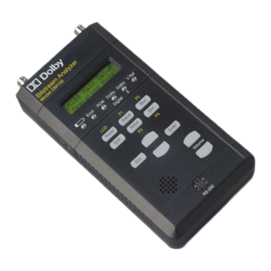
Summary of Contents for Dolby Laboratories DM100
- Page 2 AES3 channel status is being modified in Passthrough Mode. See Section 4.3. Power V Ref Hold for two seconds to turn DM100 on or off Green: A valid video reference input signal is present, and unit is in a mode that requires it...
- Page 3 Telephone (44) 1793-842100 Fax (44) 1793-842101 Dolby and the double-D symbol are registered trademarks of Dolby Laboratories. Surround EX is a trademark of Dolby Laboratories. Toslink is a trademark of Toshiba Corporation. Windows is a registered trademark of Microsoft Corporation. All other trademarks remain the property of their respective owners.
-
Page 4: Table Of Contents
® Dolby DM100 User’s Manual Table of Contents Chapter 1 Introduction 1.1 About the DM100..........1-1 Chapter 2 Getting Started 2.1 Power..............2-1 Battery Installation ........2-1 [Power] Button ...........2-2 Battery Low LED........2-2 Auto-Power Off..........2-2 2.2 Rear Belt Clip/Stand..........2-3 2.3 Inputs ..............2-4 Dolby Digital..........2-4 Dolby E ............2-4... - Page 5 ® Dolby DM100 User’s Manual Chapter 3 Operation: Status Mode 3.1 Main Status Screen..........3-1 Dolby E ............. 3-2 Dolby Digital ..........3-3 PCM ............3-3 NULL Data ..........3-4 Pause Data..........3-4 Data Type X..........3-4 3.2 The Status Menus ..........3-5 3.2.1 Dolby E Metadata Input Menu....
- Page 6 DD Sample Rate.........3-22 DD Bitstream ID ........3-22 DD Stream #..........3-23 3.2.3 AES3 Status Menu ........3-24 3.2.4 Input Level Menu........3-26 3.2.5 Generator Status Display......3-27 3.2.6 Video Reference Status Display....3-28 3.2.7 Timecode Status Display......3-29 3.2.8 Error Stats Menu ........3-30 3.2.9 DM100 Firmware Version ......3-31...
- Page 7 5.2 Unit Reset .............. 5-3 Restore Default Settings ......5-3 Hardware Reset.......... 5-3 5.3 Connector Pinout Information....... 5-4 5.3.1 RS-232 Serial Port ........5-4 5.3.2 XLR Connectors ........5-4 5.3.3 Headphone Connector........ 5-4 5.4 DM100 Specifications........... 5-5 5.5 System Block Diagram.......... 5-2...
-
Page 8: Chapter 1 Introduction
The unit allows audio systems integrators and service engineers to quickly test the integrity and composition of these signals throughout a facility. The DM100 is intended for use in broadcast, cable, DBS, and postproduction facilities, as well as DVD mastering and home theater installation. -
Page 9: Chapter 2 Getting Started
Chapter 2 Getting Started Power The DM100 is powered by four standard AA 1.5 V batteries or from an external 6V, 800 mA DC power supply via the power input connector. The internal batteries are disconnected when the external DC power supply is used. -
Page 10: [Power] Button
Dolby DM100 User’s Manual Getting Started [Power] Button To turn on the DM100, press and hold the [Power] button down for two seconds. The display reads as shown for approximately one second while a self-test diagnostic runs. Model DM100 Unit Name The power-on process ends with the DM100 operating in the last-used state. -
Page 11: Rear Belt Clip/Stand
LCD Backlight setting. See Section 4.6 for more information. Rear Belt Clip/Stand The pull-out clip on the rear of the DM100 can be used as a handy belt clip or a stand. Raise the clip by following these two steps: 1. -
Page 12: Inputs
(i.e., one 16-bit mode bitstream in each AES3 channel). Dolby E The DM100 accepts 16-, 20-, and 24-bit Dolby E bitstreams at NTSC (29.97 fps), PAL (25 fps), 23.98 fps, 24 fps, and 30 fps rates. If the input signal does not contain a header indicating that a pre- encoded bitstream is being received, the DM100 assumes the input signal is PCM audio. -
Page 13: Outputs
® Dolby DM100 User’s Manual Getting Started Outputs The XLR and BNC output connectors are always active. The Toslink connector is enabled when it is selected. The digital output signal can be: Pass-through Dolby Digital, Dolby E, or PCM. The output clock is locked to the digital input. -
Page 14: Hookup
® Dolby DM100 User’s Manual Getting Started Hookup Figure 2-1 shows the locations for connecting components to the DM100. RCA F to BNC M Part Number 70218 Ref Video In BNC F to RCA M Part Number 70217 Toslink Cable... -
Page 15: Quick Start
Dolby DM100 User’s Manual Getting Started Quick Start The DM100 is designed to be easy and intuitive to use. Follow these simple procedures to begin taking your first readings and generating your first test streams. Making Your First Reading 1. Turn on the unit by pressing [Power]. -
Page 16: Advanced Features
Getting Started Advanced Features Measuring the Latency of Equipment The DM100 can be used to measure the latency of other audio equipment. At user-defined intervals, the DM100 generates a short burst of white noise, then measures the time taken for the signal to return. - Page 17 1. Go to the Gen Control / Output Mode setup menu, and select A/V Freq Drift (see Section 4.2). 2. Connect a 29.97 or 25 fps video reference to DM100’s V Ref input. 3. Connect the test AES signal to the DM100’s Digital In.
-
Page 18: Chapter 3 Operation: Status Mode
DM100 User’s Manual Chapter 3 Operation: Status Mode After power-on, the DM100 defaults to Status mode, with the top-level main status screen displayed. Status mode is used for displaying, monitoring, and analyzing the input bitstream. Note: References to the front-panel buttons are shown using brackets throughout this manual (e.g., “[Status]”). -
Page 19: Dolby E
® Dolby DM100 User’s Manual Operation: Status Mode Dolby E ® When the incoming bitstream is Dolby E, the following information will be displayed: Dolby E 5.1+2 24bit Program Configuration 5.1+2 Bit Depth 16bit 5.1+2x1 20bit 24bit 4+2x2 4+2+2x1 4+4x1... -
Page 20: Dolby Digital
256kbps 2/1L 320kbps 3/1L 384kbps 2/2L 448kbps 3/2L 512kbps 576kbps 640kbps When the incoming bitstream is PCM, and the DM100 has locked to it, the following information will be displayed: 44.1 kHz 48 kHz 44.1 kHz 32 kHz Unknown Rate... -
Page 21: Null Data
® Dolby DM100 User’s Manual Operation: Status Mode NULL Data When the incoming bitstream is Null data, as defined in the IEC 61937 or SMPTE 337M standards, the following screen is displayed: NULL data Pause Data When the incoming bitstream is Pause data, as defined in the... -
Page 22: The Status Menus
® Dolby DM100 User’s Manual Operation: Status Mode The Status Menus From the top-level main Status display described above, you can step through the status menus by pressing the [Up] or [Down] button. Each menu below the top main Status display is described in the following manual sections. -
Page 23: Dolby E Metadata Input Menu
Px Copyright Line xxx Refer to SMPTE-170M and ITU-R [Down]▐ BT.470-6 for video line structure. Px Orig Bitstrm Dolby E input not present or DM100 [Down]▐ blank decode format is not Dolby E. Px Extnd Bitstrm Video reference not present. -
Page 24: Px Prog Desc
Dolby E program description display: Px Prog Desc Description text The DM100 has a 32-character buffer for each program, which stores the first characters in the description text field for that program. The display scrolls through the text automatically if the string is greater than 16 characters. -
Page 25: Px Channel Mode
® Dolby DM100 User’s Manual Operation: Status Mode Px Channel Mode A typical example is shown for the Dolby E Channel Mode display: P2 Channel Mode 2/0 Stereo 1/0 Mono 2/0 Stereo Px LFE Channel P2 LFE Channel Disabled Disabled... -
Page 26: Px Line Mode Pro
® Dolby DM100 User’s Manual Operation: Status Mode Px Line Mode Pro Px RF Mode Pro The Dolby E Line Mode and RF Mode Profile program parameters display the same second-line display. A typical example is shown for the RF Mode Profile display:... -
Page 27: Px Center Dwnmx
® Dolby DM100 User’s Manual Operation: Status Mode Px Center Dwnmx A typical example is shown for the Dolby E Center Downmix display: P2 Center Dwnmx 0.500 (-6.0 dB) 0.707 (-3.0 dB) 0.596 (-4.5 dB) 0.500 (-6.0 dB) *************** Px Srnd Dwnmx... -
Page 28: Px Mixing Level
® Dolby DM100 User’s Manual Operation: Status Mode Px Mixing Level A typical example is shown for the Dolby E Mixing Level display: P2 Mixing Level 80 dB 80 dB 81 dB 82 dB • • • 111 dB Does Not Exist... -
Page 29: Px Extnd Bitstrm
® Dolby DM100 User’s Manual Operation: Status Mode Px Extnd Bitstrm A typical example is shown for the Extended Bitstream metadata display. Other possibilities are also shown: Px Extnd Bitstrm P2 Pref Dwnmx ENTER to view Lt/Rt Not Indicated Px Pref Dwnmx... -
Page 30: Px Dc Filter
Enabled Px Srnd Ph Shift When any of these Dolby E metadata programs is selected, the DM100 displays the same information as shown in the example. A typical example is shown for the Dolby E Lowpass Filter display. Px Begin Gain... -
Page 31: Dolby Digital Metadata Input Menu
® Dolby DM100 User’s Manual Operation: Status Mode 3.2.2 Dolby Digital Metadata Input Menu After pressing [Enter] to select this function, press the [Down] or [Up] button to select the parameter you wish to display. Dolby Digital MD ENTER to View DD Dialogue Lev [Down]▐... -
Page 32: Dd Dialogue Lev
® Dolby DM100 User’s Manual Operation: Status Mode DD Dialogue Lev A typical example is shown for the Dolby Digital Dialogue Normalization Status display: DD Dialogue Lev –27 dB *************** –1 dB –2 dB –3 dB • • • –31 dB... -
Page 33: Dd Data Rate
Main Complete Main M & E Assc Visual Imp Assc Dialogue Assc Commentary Assc Emergency Assc Voice Over Main Sv Karaoke “N/A” indicates that a Dolby Digital input is not present, or the DM100 decode format is not Dolby Digital. 3-16... -
Page 34: Dd Line Mode Pro
® Dolby DM100 User’s Manual Operation: Status Mode DD Line Mode Pro DD RF Mode Pro The Dolby Digital Line Mode and RF Mode Profile parameters use the same display style. A typical example is shown for the RF Mode Profile display: DD RF Mode Pro ±xx dB... -
Page 35: Dd Srnd Dwnmx
® Dolby DM100 User’s Manual Operation: Status Mode DD Srnd Dwnmx A typical example is shown for the Dolby Digital Surround Downmix display: DD Srnd Dwnmx 0.707 (-3.0 dB) 0.707 (-3.0 dB) 0.500 (-6.0 dB) 0 (-999 dB) *************** Not Active... -
Page 36: Dd Room Type
® Dolby DM100 User’s Manual Operation: Status Mode DD Room Type A typical example is shown for the Dolby Digital Room Type display: DD Room Type Large Not Indicated Large Small ************** Does Not Exist DD Copyright DD Orig Bitstrm A typical example is shown for the Dolby Copyright status display. -
Page 37: Dd Extnd Bitstrm
® Dolby DM100 User’s Manual Operation: Status Mode DD Extnd Bitstrm A typical example is shown for the Extended Bitstream information display. Other possibilities are shown: Px Extnd Bitstrm DD Pref Dwnmx ENTER to view Lt/Rt Not Indicated DD Pref Dwnmx... -
Page 38: Dd Dual Mono Md
® Dolby DM100 User’s Manual Operation: Status Mode DD Dual Mono MD After pressing [Enter] to select this function, press the [Down] or [Up] button to select the Dual Mono metadata parameter you wish to display. A typical example screen is shown:... -
Page 39: Dd Format
® Dolby DM100 User’s Manual Operation: Status Mode DD Format A typical example is shown for the Dolby Digital Format status display: DD Format Pro 32-bit Pro 32-bit Pro 16-bit Ch1 Pro 16-bit Ch2 Pro 16-bit Ch1&2 Consumer DD Sample Rate... -
Page 40: Dd Stream
® Dolby DM100 User’s Manual Operation: Status Mode DD Stream # A typical example is shown for the Dolby Digital Stream Number status display: DD Stream # • • 3-23... -
Page 41: Aes3 Status Menu
® Dolby DM100 User’s Manual Operation: Status Mode 3.2.3 AES3 Status Menu After pressing [Enter] to select this menu, press the [Down] or [Up] button to select the AES3 parameter you wish to display. A typical example screen is shown:... - Page 42 ® Dolby DM100 User’s Manual Operation: Status Mode Continued from previous page [Down]▐ Cons Chan Status Enter to View 2ch No Pre-Emph Copyright Reserved 1—3 [Down]▐ 2ch 50/15us [Down]▐ Reserved (5—7) Additional Info [Down]▐ XX represents the Category Code Not Indicated category code number 1—15...
-
Page 43: Input Level Menu
® Dolby DM100 User’s Manual Operation: Status Mode 3.2.4 Input Level Menu Press [Enter] to display Input Level status. The display combinations are shown below. A typical example screen is shown: Input is Dolby E Input is Dolby Digital Displays program Prog 1—8... -
Page 44: Generator Status Display
The latency between the The unit is in blank output and input of the Pass Through mode. Pass Through DM100 in samples or ms. xxxx.x samples Press [enter] to switch between samples and time. The unit is in Measured Latency time Latency Test mode. -
Page 45: Video Reference Status Display
® Dolby DM100 User’s Manual Operation: Status Mode 3.2.6 Video Reference Status Display A typical example is shown for the Video Reference input status display: Video Ref 29.29 fps 25 fps Frame Rate. 29.97 fps No video input. No Input Video Ref Video input present but invalid. -
Page 46: Timecode Status Display
® Dolby DM100 User’s Manual Operation: Status Mode 3.2.7 Timecode Status Display Timecode frame rate: 23, 24, 25, 29, or 30 (23=23.98 fps) (29=29.97 fps) Timecode xx 00:00:00:00 Timecode Timestamp data burst delay, if present, indicates the encode latency referenced to A/V sync. -
Page 47: Error Stats Menu
The first screen displays any current error condition that prevents correct operation of the DM100. Subsequent screens display a historical count of errors. Error counts over 99 display as 99. Press [Enter] to reset a displayed error count to 00. -
Page 48: Dm100 Firmware Version
Operation: Status Mode 3.2.9 DM100 Firmware Version This last Status menu item displays the version of the firmware currently installed in your DM100. Firmware Version 2.0.0.0 Pressing [Down], [Esc], or [Status] returns the display to the top-level Main Status screen. -
Page 49: Chapter 4 Operation: Setup Mode
Chapter 4 Operation: Setup Mode Introduction Pressing [Setup] switches the DM100 into Setup mode. Use this function to configure your DM100. All setup settings are saved when the unit is turned off. The settings shown in bold are the factory defaults. The setup menu choices are:... -
Page 50: Monitor Control
Decode Format chooses the type of bitstream the DM100 will decode. This is normally set to Autodetect; however, it is possible to force the DM100 to decode only one stream type, if required. Output Ch Map chooses which audio channels or downmix (Lt,Rt or Lo,Ro) are output from the headphone or speaker. - Page 51 ® Dolby DM100 User’s Manual Operation: Setup Mode DM100 Main Setup [Enter] Monitor Control Autodetect Monitor Control [Enter] Dolby E Decode Format Dolby Digital [Down]▐ Monitor Control [Enter] Output Ch Map L=Lo R=Ro L=Lt R=Rt [Down]▐ L=L R=R Monitor Control...
-
Page 52: Gen Control
PC to the DM100 using the supplied cable. The baud rate is fixed at 115.2 kbps. Activate the Upload Bitstream function on the DM100 and follow the prompts on the PC software supplied. During the upload, the DM100 display will show progress. When complete, reboot using the [Esc] key. - Page 53 ® Dolby DM100 User’s Manual Operation: Setup Mode DM100 Main Setup [Enter] Gen Control Generator Latency Test A/V Freq Drift [Enter] Pass Through Gen Control Output Mode [Enter] [Down]▐ DE stream names Gen Control DD stream names Gen Stream Sel [Enter] [Down]▐...
-
Page 54: Aes3 Output
AES3 Output The AES3 Output menu allows the user to control the value of the AES3 status bits present on the output of the DM100. The output can be set to pass through each parameter from the input (or from the generator), or each parameter can be manually set to a desired value. - Page 55 ® Dolby DM100 User’s Manual Operation: Setup Mode DM100 Main Setup [Enter] AES3 Output Professional Not Indicated AES3 Output Consumer Reserved (1—3) AES3 Mode No Emphasis Pass Through Reserved (5) [Down]▐ 50/15-us Emph AES3 Output Audio J.17 Emph Audio Mode...
-
Page 56: User Presets
Dolby DM100 User’s Manual Operation: Setup Mode User Presets Up to four user presets can be saved, named, and recalled. These presets contain a copy of the DM100 setup information. DM100 Main Setup [Enter] User Presets 01-<name 1> User Presets [Enter] 02-<name 2>... -
Page 57: I/O Control
I/O Control The I/O control menu configures the physical input and output connections of the DM100. Input Select allows the user to choose a specific physical input rather than the default of Autodetect. Gen Clock Source chooses the reference signal for the generator. -
Page 58: System Settings
DM100. RS-232 Baud Rate controls the speed of the RS-232 port logging data. Unit Name allows entry of up to 12 characters to give a DM100 a unique identity. This is displayed during power on. The Power Management function controls how long the unit remains switched on after the last button press when operating on battery power. - Page 59 ® Dolby DM100 User’s Manual Operation: Setup Mode Note: When powered from the external power supply, the Power Management setting is ignored and the unit remains switched on. The LCD backlight and keypad backlights are also turned on, overriding the LCD Backlight setting.
-
Page 60: Chapter 5 Reference Information
® Dolby DM100 User’s Manual Chapter 5 Reference Information Data Transfer Connect the RS-232 port on the front of the DM100 to a computer using the cable provided. The RS-232 serial interface is used for: • Test bitstream loading. •... -
Page 61: Firmware Upgrade
See Sections 4.5 and 4.6. Firmware Upgrade With the DM100 powered off, press the [Power] button, then hold down the [Setup] button. The DM100 will display the Firmware Upgrade screen. The data transfer operates at a fixed data rate of 115.2 kbps. -
Page 62: Unit Reset
In the unlikely event that the restore procedure above does not work, the unit can also be reset by inserting a pen point or paper clip into the RESET hole on the back of the DM100. The unit will reset and power off. -
Page 63: Connector Pinout Information
® Dolby DM100 User’s Manual Reference Information Connector Pinout Information 5.3.1 RS-232 Serial Port Connection Description Asynchronous data out Ground Asynchronous data in Note: This unit is a DCE device designed for connection to a DTE device. The TX is the data input and the RX is the data output 5.3.2... -
Page 64: Dm100 Specifications
® Dolby DM100 User’s Manual Reference Information DM100 Specifications Sampling Rates Headphone Output 48 kHz for all modes, +5.8 dBu max (adjustable) into 600Ω, 32 kHz and 44.1 kHz for Dolby Digital 1/8-inch standard stereo headphone jack and PCM Case... -
Page 65: System Block Diagram
DM100 User’s Manual Reference Information System Block Diagram...
Need help?
Do you have a question about the DM100 and is the answer not in the manual?
Questions and answers