Advertisement
Quick Links
DQ170 Series Quick Guide【English】
__p
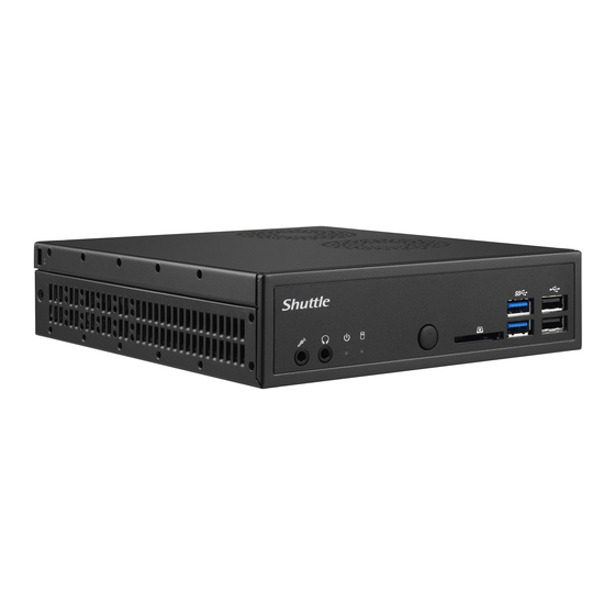
Front Panel
F1. MIC-in
F2. Headphone
F3. Power LED
F5
F6
F7
F8
F4. HDD LED
F5. Power Button
F6. SD Card Reader
F7. USB 3.0 Port
F8. USB 2.0 Port
F1 F2 F3
F4
Back Panel
B1. COM1 Port
(RS232/RS422/RS485)
B2. COM2 Port (RS232 only)
B1
B2
B3. Power Jack (DC IN)
B4. HDMI Port
B5. DisplayPort
B6. LAN Port
B7. USB 3.0 Port
B8. USB 2.0 Port
B3
B4
B5
B6
B7
B8
B9
B9. Clear CMOS & Power
Button
Left / Right Panel
®
Kensington
Lock Port
Kensington
Motherboard Illustration
Power Button-SW2
SD Card Reader Slot
USB 3.0 (x2) Port
USB 2.0 (x2) Port
AC Back Auto
Power ON-JP2
J1
Fan Connector
J2
-FAN1
SATA 3.0 6Gb/s
Connector
LGA1151 Package
CPU Socket
Intel Q170 Chipset
DC IN
HDMI Port
DisplayPort
Jumper Settings
AC Back Auto Power ON
J1
DEFAULT =>Disable, short 1-2
2
JP2
Pin
Signal Name
1
U26C_pin10
2
GND
Fan Connector
J2
4 3 2 1
FAN1
Pin
Signal Name
1
Ground
2
+12V
3
SPEED_SENSE
4
PWM_CTRL
Audio Connector
J3
13
14
12
11
10
9
8
7
6
5
4
3
1
2
AUDIO1
Pin
Signal Name
Pin
Signal Name
1
AGND
2
LINE-R
3
NA
4
LINE-L
5
AGND
6
FRONT_L
7
NULL
8
FRONT_SENSE
9
AGND
10
FRONT_R
11
BK_AUDIO-JD
12
MIC1_R
13
AGND
14
MIC1_L
®
Lock Port
SATA Power Connector
J4
1
2 3
4
PW1
Pin
Signal Name
1
GND
HDD LED
2
GND
Power LED
3
+5V
Headphone
4
+5V
MIC-in
Audio Connector
J3
-AUDIO1
COM Port
J5
SATA Power
J4
Connector-PW1
2
4
6
8 10
DDR3L SODIMM
1
3
5
7
9
Slot
COM1&COM2
COM1 & COM 2
J6
Power Switch-JP1
Pin
Signal Name
Pin
Signal Name
1
DCD
2
RX
COM Port-
J5
COM1,COM2
3
TX
4
DTR
5
GND
6
DSR
Debug Header-DBG1
7
RTS
8
CTS
9
RI(NA)
10
NA
USB Header
J7
Mini PCIe Slot
VGA Connector-CN6
Safety Information
M.2 Slot
Read the following precautions before setting up a Shuttle XPC.
Battery
Connector-CN1
CAUTION
Clear CMOS&Power
J8
Button-SW1
Incorrectly replacing the battery may damage this computer.
USB 2.0 (x2) Port
Replace only with the same or equivalent as recommended by Shuttle.
USB 3.0 (x2) Port
Dispose of used batteries according to the manufacturer's instructions.
LAN Port-LAN1,LAN2
62R-DQ1700-5201
English.Spanish.Korean.
Traditional Chinese.Japanese.
French. German Quick Guide
COM1 & COM2 Power Switch
J6
Pin 9 "Ring Indicator" (RI) configuration
Configure COM 1 with the first jumper:
- short Pin 1-2: Pin 9 = RI (default)
- short Pin 5-7: Pin 9 = +5V
- short Pin 7-9: Pin 9 = +12V
1
Configure COM 2 with the second jumper:
- short Pin 3-4: Pin 9 = RI (default)
- short Pin 6-8: Pin 9 = +5V
- short Pin 8-10: Pin 9 = +12V
JP1
Pin
Signal Name
Pin
Signal Name
1
-XRI1(NA)
2
COM_-XRI1(NA)
3
-XRI2(NA)
4
COM_-XRI2(NA)
5
+5V
6
+5V
7
COM1_PWR
8
COM2_PWR
9
+12V
10
+12V
A. Begin Installation
For safety reasons, please ensure that the power cord is
disconnected before opening the case.
1. Unscrew the two screws of the chassis cover.
2. Slide the cover backwards and upwards.
2
1
3. Unfasten the rack mount screw and remove the rack.
B. CPU and ICE Module Installation
1. Unfasten the four ICE module attachment screws and unplug the fan
connector.
2. Remove the ICE module from the chassis and put it aside.
Please note the pins of the LGA 1151 socket bend easily.
Always apply extreme care and little force when installing a CPU
and limit the number of times you remove or exchange it. Before
installation, make sure to turn off the computer and unplug the
power cord from the mains to avoid damage.
Follow the steps below to correctly install the CPU into the
motherboard CPU socket.
3. First unlock and raise the socket lever.
4. Tear off the protective membrane from the metal load plate. Lift the
metal load plate from the CPU socket.
The product's colour and specifications may vary from the actually shipping product.
L
USB Header
J7
Pin
Signal Name
1
5V_USB
10
9
3
USB A-
8
7
5
USB A+
6
5
7
GND
4
3
9
NULL
2
1
Clear CMOS & Power Button
J8
Pin
Signal Name
1
RTCRST-
3
GND
DO NOT touch socket contacts. To protect the CPU socket, always
replace the protective socket cover when the CPU is not installed.
5. Please orientate the CPU correctly and align the CPU notches with the
socket alignment keys. Make sure the CPU sits perfectly horizontal,
then push it gently into the socket.
Triangle Pin1
Marking on the CPU
Socket
1151
CPU
Notch on the CPU/
Alignment Key of the
CPU Socket
Please be aware of the CPU orientation, DO NOT force the CPU into
the socket to avoid bending of pins and damage of the CPU!
6. Close the metal load plate, lower the CPU socket lever and lock in place.
7. Spread thermal paste evenly on the CPU surface.
Metal load plate
Thermal Paste
application area
Retention tab
Load lever
Please do not apply excess amount of thermal paste.
8. Screw the ICE module to the mainboard. Note to press down on the
opposite diagonal corner while tightening each screw.
HDD Rack
9. Connect the fan connector.
3
1
2
4
Fan connector
Fan connector
C. Memory Module Installation
This mainboard does only support 1.35V DDR3L SO-DIMM
memory modules.
1. Locate the SO-DIMM slot on the mainboard.
2. Align the notch of the memory module with the one of the memory slot.
SO-DIMM slot
notch
3. Gently insert the module into the slot in a 45-degree angle.
4. Carefully push down the memory
module until it snaps into the
locking mechanism.
1
Tear off the protective
membrane.
Metal load plate
2
45-degree
angle
USB3
2
4
6
8 10
Pin
Signal Name
2
5V_USB
4
USB B-
1
3
5
7
9
6
USB B+
8
GND
10
GND
SW1
2
4
Pin
Signal Name
1
3
2
+5V
4
PWRSW-
3
Latch
Latch
5. Repeat the above steps to install additional memory modules, if required.
D. Component Installation
1. As shown, unfasten the screw first.
Mini PCIe Slot
M.2 Slot
2. Install the Mini PCIe card / M.2 SSD into the Mini PCIe slot / M.2 slot
and secure with the screw.
3. Place a HDD or SSD in the rack and secure with the four screws from
the side.
4. Connect the Serial ATA and power cables to the HDD or SSD.
Slide the rack into the chassis and refasten the screws.
Serial ATA Cable
Serial ATA Power Cable
E. Complete
1. Replace the cover and refasten the screws.
2 . Complete.
Please press the "Del" key while booting to enter BIOS. Here,
please load the optimised BIOS settings.
53R-DQ1703-H001
Advertisement


