
Related Manuals for YOKOGAWA 51011


Summary of Contents for YOKOGAWA 51011
- Page 1 User’s 51011, 51012, 51021 Manual Digital Lux Meter Store this manual in an easily accessible place for quick reference. IM 51011-01EN 4th Edition: Oct. 2017 (YMI)
-
Page 2: Introduction
Please read all manuals. IM 51011-01E User's Manual (this manual) IM 51011-93Z2 Document for Korea Contact information of Yokogawa offices worldwide is provided on the following sheet. PIM 113-01Z2 Inquiries List of worldwide contacts Notes •... - Page 3 • October 2013 2nd Edition • May 2013 3rd Edition • October 2017 4th Edition 4th Edition: October 2017 (YMI) All Rights Reserved, Copyright © 2013, Yokogawa Meters & Instruments Corporation, 2017, Yokogawa Test & Measurement Corporation Printed in Japan IM 51011-01EN...
-
Page 4: Checking The Contents Of The Package
If the wrong items have been delivered, if items are missing, or if there is a problem with the appearance of the items, contact your nearest YOKOGAWA dealer. Digital Lux Meter Check that the product that you received is what you ordered by referring to the model name on the name plate. -
Page 5: Conventions Used In This Manual
Note Calls attention to information that is important for the proper operation of the instrument. IM 51011-01EN... -
Page 6: Safety Precautions
This manual is an essential part of the product; keep it a safe place for future reference. YOKOGAWA assumes no liability for the customer’s failure to comply with these requirements. The following symbols are used on this instrument. - Page 7 • Do not wipe the meter with organic solvents. Dirt or dust adhering to the light-detecting surface of the meter decreases measurement accuracy. Wipe the surface clean with a soft, dry cloth. • Do not separate the light-detector from the main unit with the power on. IM 51011-01EN...
-
Page 8: Measurement Category
For measurement performed in Distribution board, CAT III the building installation. circuit breaker, etc. For measurement performed at Overhead wire, CAT IV the source of the low-voltage cable systems, etc. installation. IM 51011-01EN... -
Page 9: Table Of Contents
21. Illuminance Measurement Method ..... . . 52 22. For the Pollution Control of Electronic and Electrical Products of the People's Republic of China..55 IM 51011-01EN... -
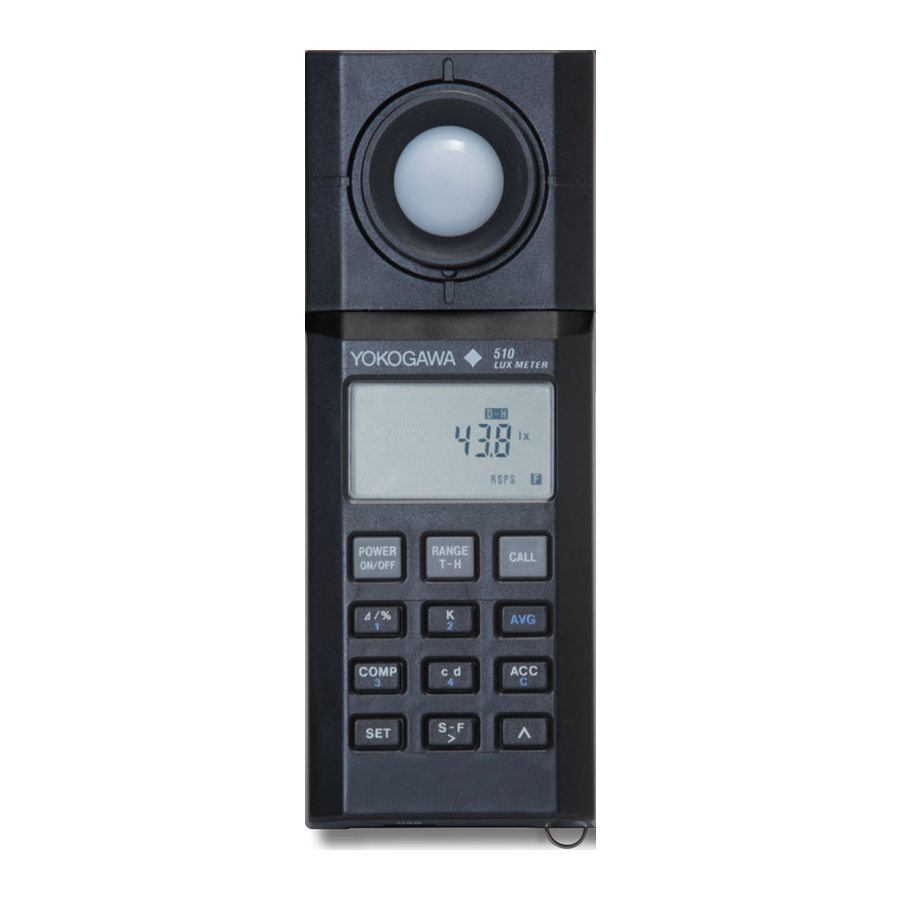
Page 10: Component Names And Functions
Light-detecting surface (using an extension cable) Main unit Display POWER key Turns the power Keys on and off Hand strap USB port (mini B type) Use the USB cable to communicate to the PC and supply power. IM 51011-01EN... - Page 11 K Key Use this key in color correction measurement. Color corrected results are displayed. A switch is made between normal measurement and color correction measurement each time you press this key. You can also set the color correction factor. IM 51011-01EN...
- Page 12 A switch is made between normal measurement and ripple measurement each time you press the key. SET Key Use this key to configure various settings. Key and Use these keys to move the setting position and change values. IM 51011-01EN...
- Page 13 Eject button Used to separate the light detector from the main unit Hold switch Battery cover Response selector Holds the measured switch data reading Switches the light detector response speed between FAST and SLOW IM 51011-01EN...
- Page 14 Timer hold-time unit (seconds) Unit for illuminance measurement Unit for integral time of totalized intensity of illumination Deviation display % Unit for the distance to the light source Unit for luminous intensity; lights during light source luminous intensity measurement IM 51011-01EN...
-
Page 15: Before Operation
Only the color correction function can be used in combination with another function. Operation of other measurement functions are not allowed except for the normal luminance measurement and color correction measurement screens. 2.2 Turning the Power On and Off CAUTION Check that the meter operates normally. IM 51011-01EN... -
Page 16: Setting The Response
(automatic zero-adjustment mode). Then, the display shows the luminance measurement [0.00 lx] display. ([0.0 lx] appears on Model 51011 and 51012.) If you press the POWER key again, the meter will turn off. (See chapter 3, “Normal Illuminance Measurement,” and section 17.1, “Error Messages.”) -
Page 17: Checking And Replacing Batteries
The automatic power-off function is disabled while the totalized intensity of illumination or comparator function is being executed or when a plug is inserted in the recorder output connector. When the automatic power-off function is enabled, [AUTO POWER OFF] is displayed. IM 51011-01EN... - Page 18 Cover the light-detecting surface with the cap. (Check that the HOLD switch is not locked.) Press the POWER key again to turn on the power. After the initial display, [AUTO POWER OFF] appears, and the automatic power-off function returns. IM 51011-01EN...
-
Page 19: Notes On Illuminance Measurement
• When you measure for long period of time, the zero point may change due to large changes in the ambient temperature. In such a case, turn off the power once and then turn it on again. (See the procedure in chapter 3, “Normal Illuminance Measurement.”) IM 51011-01EN... -
Page 20: Normal Illuminance Measurement
When the adjustment is finished, [--CAL--] disappears. (Initial display end) The illuminance measurement [0.00 lx] display appears. ([0.0 lx] appears on Model 51011 and 51012.) Note: If the [--CAP--] display persists, the cap may not be on correctly. Put the cap on correctly. (The cap may be broken.) Starting to Measure Remove the cap, and start measuring. -
Page 21: Color Correction Measurement (K Key)
* The color correction factors are calculated based on the relative spectral distribution values of JIS Z 8719, JIS Z 8720, and CIE No. 53TC.2 lamps. JIS: Japanese Industrial Standards CIE: Commission Internationale de l'Éclairage (International Commission on Illumination) IM 51011-01EN... - Page 22 • The color correction factors on the previous page—(1) FLd 0.994 to (8) Wt 0.997—are typical values.Each meter product has its own color correction factors (different from typical values), which have been memorized before shipping according to its characteristics. IM 51011-01EN...
-
Page 23: Timer Hold (Hold And T-H Keys)
51011 and 51012 timer setting: 5 seconds (fixed) 51021 timer setting: 000 to 999 seconds (as specified) Setting the Timer (on Model 51021) - Page 24 When the specified time elapses, the meter beeps and holds the measured value at that point. [D-H] stops blinking. To make another measurement, press again. HOLD To release the timer hold, press again. [D-H] disappears, and the meter returns to normal measurement mode. IM 51011-01EN...
-
Page 25: Range Hold (Range Key)
RANGE To return to auto range mode, hold down for at least 1 second. [R-H] disappears. Note To view the range during measurement, cover the light-detecting surface with the cap so that the illuminance is zero. IM 51011-01EN... -
Page 26: Average Illuminance (Avg Key)
If you hold down a number key for a location in which a value is stored for more than 1 second, the value is deleted, and the location number disappears from the display. IM 51011-01EN... - Page 27 • To view the value of a location while the measured result is displayed, hold down the number for the location. IM 51011-01EN...
-
Page 28: Deviation Display (Δ/% Key)
Δ/%. CALL To view the reference value, hold down Δ/% To return to the normal measurement display, hold down for at least 1 second. Note If the measured value falls outside the measurement range, [OL] will appear. IM 51011-01EN... -
Page 29: Light Source Luminous Intensity (Cd Key)
Face the light-detecting surface of the lux meter towards the light source. Take a measurement at the specified distance. CALL To view the distance that you have specified, hold down Read the value. To return to normal measurement, press . [cd] disappears. IM 51011-01EN... -
Page 30: Totalized Intensity Of Illumination (Acc Key)
To use the comparator function, set the limit value. Note If the battery runs low during long-term totalization, an error may be introduced in the calculation. To perform long-term totalization, we recommend that you supply power through USB. IM 51011-01EN... - Page 31 Example of how to set 1230000 Display for setting Display for setting the top digits the remaining (lowest) digits After entering the value, press [SET] disappears, and the setting is complete. IM 51011-01EN...
- Page 32 To return to the normal illuminance measurement, hold down for at least 1 second. Note If the totalized intensity of illumination or integral time reaches its maximum value, totalization stops. [D-H] appears. IM 51011-01EN...
-
Page 33: Comparator (Comp Key)
. The display for setting the high limit appears. Set the high limit in the same manner as in step 2. COMP (Press to switch between high and low limits.) After entering the values, press . The setting is complete, and [SET] disappears. IM 51011-01EN... -
Page 34: Ripple Measurement (S-F Key)
This method is disadvantageous in that taking measurements at the same location and height when the lamps are turned on and when they are turned off is difficult, which results in errors. IM 51011-01EN... - Page 35 Illuminance = DC component (Lr) × Ripple ratio The ripple ratio must be determined in advance through the measurement of the total illuminance of the room and ambient light Lg. The lux meter can use the ripple ratio and AC component measurements to calculate illuminance. IM 51011-01EN...
- Page 36 The set ripple ratio is retained even when the power is turned off (the ratio is retained until it is changed). Ripple Measurement Press . [S-F] appears, and measurement starts. CALL To view the ripple ratio, hold down To return to normal measurement, press . [S-F] disappears. IM 51011-01EN...
-
Page 37: Communication Functions
Installing the USB Driver To connect the lux meter to a PC, you must first install the appropriate USB driver. USB specifications: Conforms to version 1.1 Download the driver from the YOKOGAWA’s lux meter website. http://tmi.yokogawa.com/products/portable-and-bench- instruments/luxmeters/digital-lux-meters/ Communication settings Baud rate:... -
Page 38: List Of Commands
Selects how to send data from the lux meter to the PC Enables automatic power-off Sets auto range mode Requests to send measured data Sets the range hold function Checks unsent (measured) data in buffer Sets the transmitted delimiter IM 51011-01EN... -
Page 39: Detailed Description Of Commands
= integral time: 00000.0 to 10000.0 h Yes Starts and stops the measurement of the totalized intensity of illumination Start totalized intensity of illumination: IS,m<delimiter> m = 0: OFF, 1: ON → Response: IS,m<delimiter> m = 0: successful, 1: error IM 51011-01EN... - Page 40 Note: If this command is received while totalized intensity of illumination or comparator measurement is in progress, the command will be executed after the meter returns to normal measurement. → Response: PO,m<delimiter> m = 0: successful, 1: error IM 51011-01EN...
- Page 41 = 0: no unsent data, 1: unsent data available Yes Sets the transmitted delimiter Set the delimiter: TM,m<delimiter> m = 0: CRLF (default) 1: LF 2: 0x03 → Response: 0<delimiter that was set before the TM command was received > IM 51011-01EN...
-
Page 42: Recorder Output (Analog Output)
Set the appropriate range. For details on setting the range, see chapter 6, “Range Hold”. Cover the light-detecting surface with the cap, and adjust the zero level of the monitoring instrument. Remove the cap and start measuring. IM 51011-01EN... -
Page 43: Separating The Light Detector
You can supply power through USB (5 VDC ± 5%) from external by connecting a off-the-shelf USB cable (mini B type) to the USB port of the lux meter. Note You can supply power through USB even when batteries are installed. IM 51011-01EN... -
Page 44: After-Sales Service
• Was the cap broken during zero adjustment? • Is the battery (voltage) appropriate? (Does Err: 2 occur even when the batteries are replaced with new ones?) 17.2 Calibration If repair or calibration is necessary, contact your nearest YOKOGAWA dealer. IM 51011-01EN... -
Page 45: Specifications
60° ± 10% 80° ± 30% Characteristics of relative visible-spectrum response: Deviation from the standard spectrum luminous efficiency f1’: within 9% Fatigue characteristics: ±2% Temperature characteristics: ±5% (at 23°C reference and a range of –10 to 40°C) Humidity characteristics: ±3% IM 51011-01EN... - Page 46 60° ± 7% 80° ± 25% Characteristics of relative visible-spectrum response: Deviation from the standard spectrum luminous efficiency f1’: within 6% Fatigue characteristics: ±1% Temperature characteristics: ±3% (at 23°C reference and a range of –10 to 40°C) Humidity characteristics: ±3% IM 51011-01EN...
- Page 47 ±3% (at 23°C reference and a range of –10 to 40°C) Humidity characteristics: ±3% Ripple measurement: Illuminance measurement of fluorescent lamps (except for high-frequency lighting) in the daytime Measuring range: 100 to 3000 lx Accuracy: at 23°C ± 2°C ± 7% of reading ± 1 digit IM 51011-01EN...
- Page 48 Common Specifications for 51011, 51012, and 51021 Photoelectric element: Silicon photodiode Display: 7-digit liquid crystal display (LCD) with function and unit displays Maximum effective display (for illuminance measurement): 999 + 0’s for place holders Overrange display: [OL] Low battery voltage display: [...
- Page 49 Approx. 40 h (when using alkaline dry cells) Input rating: Battery: 3 VDC (0.3 W) USB: 5 VDC ± 5% (0.5 W) Dimensions: Approx. 67 (W) × 177 (H) × 38 (D) mm Weight: Approx. 260 g (including batteries) USB port: mini B type IM 51011-01EN...
-
Page 50: Characteristics Of Relative Visible- Spectrum Response
Normally, the relative spectral response of a lux meter is slightly off from V(λ). So when a light source with a different spectral distribution than the source that was used to calibrate the lux meter is measured, the readings will be slightly off. IM 51011-01EN... - Page 51 The following figure shows the characteristics of the relative spectral response. Standard spectral luminous efficiency Relative spectral response 350 400 450 500 550 600 650 700 750 800 850 Wavelength (nm) IM 51011-01EN...
-
Page 52: Characteristic Of Oblique Incident Light
The following figure shows the characteristic of oblique incident light. Tolerance for Class AA –10 –20 –30 –80 –70 –60 –50 –40 –30 –20 –10 0 10 20 Angle of oblique incidence (°) IM 51011-01EN... -
Page 53: Illuminance Measurement Method
The middle of each side (the m point) and the center of gravity (the g point) shall be measured to obtain illuminances Em and Eg, and then the average illuminance for each area shall be determined according to the following expression: +2Eg) = (∑Em+2Eg) IM 51011-01EN... - Page 54 If you use Model 51021, measurements using the 4-point and 5-point methods are easy. (See chapter 7, “Average Illuminance.”) There is another method in which the average illuminance of multiple partitioned areas can be determined directly. For details, see JIS C 7612. IM 51011-01EN...
- Page 55 IM 51011-01EN...
-
Page 56: For The Pollution Control Of Electronic And Electrical Products Of The People's Republic Of China
91001, 91002 框架(塑料) × × × × ○ ○ 线路板 ASSY × × × × ○ ○ CABLE × × × × ○ ○ 环保使用期限 : 该标识适用于 SJ/T 11364 中所述,在中华人民共和国销售的电子电气 产品的环保使用期限。 只要您遵守该产品相关的安全及使用注意事项, 在自制造日起算的年限内,则不会因产品中有害物质泄漏或突发变异, 而造成对环境的污染或对人体及财产产生恶劣影响。 注) 该年数为“环保使用期限” ,并非产品的质量保证期。 零件更换的推荐周期,请参照使用说明书。 IM 51011-01EN...
Need help?
Do you have a question about the 51011 and is the answer not in the manual?
Questions and answers