Table of Contents
Advertisement
Advertisement
Table of Contents

Related Manuals for jobmate JMBMS210G


Summary of Contents for jobmate JMBMS210G
- Page 1 SAFETY AND OPERATING MANUAL 210mm MITRE SAW JMBMS210G...
-
Page 2: General Power Tool Safety Warnings
GENERAL POWER TOOL use common sense when operating a power tool. Do not use a power tool while you are SAFETY WARNINGS tired or under the influence of drugs, alcohol or medication. A moment of inattention while WARNING! Read all safety warnings and all operating power tools may result in serious instructions. -
Page 3: Safety Instructions For Mitre Saws
accessories, or storing power tools. Such placed too close to the saw blade, there is an preventive safety measures reduce the risk of increased risk of injury from blade contact. starting the power tool accidentally. c) The workpiece must be stationary and d) Store idle power tools out of the reach of clamped or held against both the fence children and do not allow persons unfamiliar... - Page 4 SYMBOLS adjustable fence is set correctly to support the workpiece and will not interfere with the blade or the guarding system. Without To reduce the risk of injury, user must turning the tool “ON” and with no workpiece read instruction manual on the table, move the saw blade through a complete simulated cut to assure there will be no interference or danger of cutting the fence.
-
Page 6: Component List
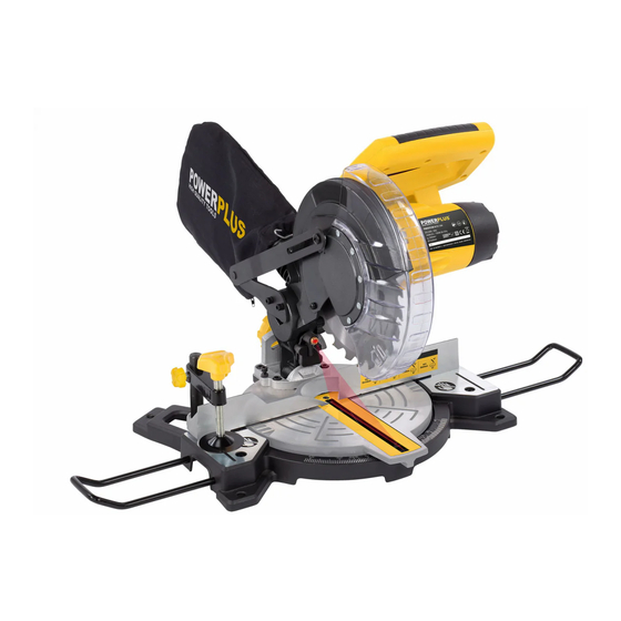
COMPONENT LIST Handle 12. Work clamp Safety release lever 13. Dust bag Carbon brush cap 14. Upper blade guard Retractable safety guard 15. Transportation handle Fence 16. Dust extraction port (See Fig. A) Rotary table 17. Left & Right extension rail (See Fig. B1, B2) Rotary table locking knob 18. -
Page 7: Intended Use
OPERATING INSTRUCTIONS NOTE: Before using the tool, read the instruction book carefully. INTENDED USE The electro-tool is intended as a stationary machine for making straight lengthways and crossways cuts in wood. Horizontal mitre angles of -45° to +45° as well as vertical bevel angles of 0°... - Page 8 Fig.B2 THE SUPPORT STAND (SEE FIG. C1,C2) Pull the support stand to its extreme, as shown in Fig. C1,C2 WARNING: Always keep the support stand at its extreme out position when using the product. 3. WORK CLAMP (SEE FIG. D) 1) The work clamp can be fitted on either side of the saw and is fully adjustable to suit the size of the workpiece.
-
Page 9: Operation
Fig.E OPERATION 1. RELEASING THE SAW HEAD (SEE FIG. F1, F2) When boxed or during storage, transportation, the saw head is locked in the down position. To release the head ready for operation, apply downward pressure and pull out the lock pin(a) The head will be raised gently to upper position. - Page 10 3. CHOP CUT (See FIG. H1, H2) Chop cut is used mainly for narrow pieces, i.e. the lock screw of slide rod is tightened and the head assembly is lowered to cut through the workpiece. 1) Connect the machine to power outlet, ensure that the mains cable is clear of the blade and base plate.
-
Page 11: Maintenance
Fig.I2 5. MITRE CUT (SEE FIG. J1, J2) A bevel cut is made at 0° mitre and any bevel angle in the range of 0° to 45° left. The saw can be moved from the normal 0° perpendicular position to an angled position down to 45° from the horizontal, on the left only. - Page 12 Fig.K2 in transit. (Ensure power is disconnected while making these adjustments). To confirm the 0o rotary table setting, set the rotary table at 0o and tighten the rotary table locking knob. Check that the angle between the straight guide and the blade is 90o using a try square (b, not supplied) as shown in Fig.
- Page 13 2. CHANGING THE SAW BLADE (SEE FIG. M1-M5) Disconnect the saw from the power supply. Remove the linkage screw with a screwdriver. Press the blade spindle lock (22) and rotate the blade until it is locked, then rotate clockwise to loosen and remove the blade securing bolt, the outer flange with the hex key.
-
Page 14: Moving The Saw
Fig.M4 3. REPLACING THE CARBON BRUSHES(SEE FIG. N1-N3) Check the carbon brushes regularly. If the carbon brushes are worn down to about 4mm, replace them with the new set (not supplied). It must be replaced in pairs. With a suitable slotted screwdriver turn the cap anti- clockwise until the carbon brush is released, replace the brush and make sure that they locate well and are secured within the brush retainer. -
Page 15: Troubleshooting
TROUBLESHOOTING Problem Probable cause Suggested remedy motor will not run 1. Switch in OFF position 1. Make sure saw is plugged in and switch is 2. No electrical power at wall pressed outlet 2. Check circuit breaker or fuse at electrical 3.
Need help?
Do you have a question about the JMBMS210G and is the answer not in the manual?
Questions and answers