Table of Contents
Advertisement
Quick Links
Advertisement
Table of Contents

Subscribe to Our Youtube Channel
Related Manuals for INTELLICYT iQue SCREENER

Summary of Contents for INTELLICYT iQue SCREENER
- Page 1 ® iQue SCREENER ® hardware manual October 2014...
-
Page 3: Table Of Contents
Table of Contents INTRODUCTION Published By Copyright Trademarks Statement of Proper Use End User Use Agreement for iQue Screening System IntelliCyt Corporation Software License Agreement Declaration of Conformity USING THIS MANUAL Conventions Terminology Text Conventions Text Symbols Safety Symbols Accessing Tech Support... - Page 4 IQUE OPERATION Introduction Cleanliness and Best Practices Safety Articles iQue Fluids Overview Preparing the Fluids Filling the Bottles Filling the Troughs A Note on Fluid Fill Level Daily Startup Overview Referenced Procedures Steps Daily QC Overview Required Materials Preparing QC Samples Creating the Daily QC Experiment Running the Water Test Interpreting the Water Test...
- Page 5 Changing the Probe and Tubing Overview Required Materials Launch the Change Probe and Tubing Wizard Replacing the Probe: Gen 1 Probe Assembly Replacing the Probe: Gen 2 Probe Assembly Attaching the New Tubing Re-Calibrating Deck Height Cleaning the New Tubing Adjusting Pump Head Tension Fluidics Maintenance Overview...
- Page 6 SPECIAL TOPICS Introduction Safety Articles First-Time Startup Checklist Overview Referenced Procedures Steps Long-Term Shutdown Checklist Overview Referenced Procedures Steps Connecting iQue Power and Data Cables Overview The iQue Uninterruptible Power Supply Connecting iQue Power Cables Connecting iQue Data 110V Power and Data Connection Diagram 220V Power and Data Connection Diagram Moving an iQue Overview...
-
Page 7: Introduction
® ® of IntelliCyt Corporation under license from the Science and Technology Corporation at the University of New Mexico. Microsoft, Windows 7, and Windows 8 are trademarks or registered trademarks of Microsoft Corporation. Other products or company names mentioned in this document may be trademarks or registered trademarks of their respective owners and are treated as such. -
Page 8: End User Use Agreement For Ique Screening System
IntelliCyt; or (c) has not been maintained in accordance with the Documentation; or (d) if the Product’s serial number has been removed or defaced; or (e) has been incorporated into a system without IntelliCyt’s review and written approval. - Page 9 This indemnification applies only to the Product delivered by IntelliCyt and shall not apply if the Product has been modified by a party other than IntelliCyt, or if the Product has been combined with (or used in connection with) other products and used as a part of an infringing process or method which, but for the combination, would not infringe the intellectual property rights of such third party.
-
Page 10: Intellicyt Corporation Software License Agreement
IntelliCyt Corporation Software License Agreement This Software License Agreement (“Agreement”) for the iQue Screener System software is entered into in conjunction with the purchase of the license to the Software. By installing and using the Software, Licensee accepts the Software and agrees to be bound by the terms of this Agreement. -
Page 11: Declaration Of Conformity
Declaration of Conformity iQue Hardware Manual: Part Number 10554 Rev C., Introduction ®... - Page 12 THIS PAGE INTENTIONALLY LEFT BLANK iQue Hardware Manual: Part Number 10554 Rev C., Introduction ®...
-
Page 13: Using This Manual
Using This Manual Conventions This guide assumes basic knowledge of computers using Microsoft Windows operating systems and familiarity with windows, menus, commands, buttons, tabs, dialog boxes, and other Microsoft Windows elements. The terminology, conventions, and symbols used in this guide are described next. Terminology Term Definition... -
Page 14: Text Symbols
Text Symbols Symbols are used in iQue documentation to draw attention to important information, such as operating tips and suggestions, as well as the presence of hazards. Symbol Description NOTE A tip, suggestion, or additional information. WARNING Indicates information that is necessary for proper Instrument or software operation. Safety Symbols The following symbols may appear adjacent to safety precaution statements. -
Page 15: Accessing Tech Support
Accessing Tech Support For help with a technical question that is not addressed within the documentation, please contact support@intellicyt com or IntelliCyt Customer Service at (505) 345-9075 Opt 2. Before contacting us, please be prepared to answer the following questions: •... - Page 16 THIS PAGE INTENTIONALLY LEFT BLANK iQue Hardware Manual: Part Number 10554 Rev C., Using This Manual ®...
-
Page 17: Safety
BEFORE CAREFULLY READING ALL INSTRUCTIONS. ALWAYS FOLLOW PRODUCT LABELING AND MANUFACTURER’S RECOMMENDATIONS. IF THERE IS ANY QUESTION AS TO HOW TO PROCEED, CONTACT INTELLICYT. IF THIS INSTRUMENT IS USED IN A MANNER NOT SPECIFIED BY THE MANUFACTURER, THE PROTECTION PROVIDED BY THE INSTRUMENT MAY BE IMPAIRED. -
Page 18: Operator Safety
Operator Safety WARNING: There is a risk of operator injury if: • The covers are not opened and/or closed with care. • All covers and panels are not closed and secured in place prior to and during instrument operation. • Contact is made with moving parts. -
Page 19: Safety Symbols And Labels
Safety Symbols and Labels Safety symbols and labels draw attention to potentially dangerous conditions. These symbols, together with text, apply to specific procedures and appear as needed on the instrument and throughout this user guide. Do not remove these labels. Biohazard/Biological Risk: Consider all materials (specimens, reagents, controls, etc.) and the areas these materials come into contact with as being potentially infectious and/or life threatening. -
Page 20: Biological Handling Precautions
Biological Handling Precautions Biological samples are potentially dangerous and/or life threatening. Adhere to proper handling procedures for samples and reagents at all times. Depending on the laboratory environment, there could be a risk of biological, chemical, or radiological contamination resulting from contact with samples, sample tubes, sample waste, the waste container, and/or associated tubing. -
Page 21: Operational Precautions
Keep cords away from heat, oil, or sharp edges. Damaged cords increase the risk of electric shock. CAUTION: The instrument must be plugged into an IntelliCyt approved uninterruptable power supply (UPS). The UPS must be plugged into a standard, grounded, or earthed mains electrical outlet, conforming to local codes. Non- grounded or non-earthed mains outlet adaptors must not be used. - Page 22 THIS PAGE INTENTIONALLY LEFT BLANK iQue Hardware Manual: Part Number 10554 Rev C., Safety ®...
-
Page 23: Getting To Know The Ique
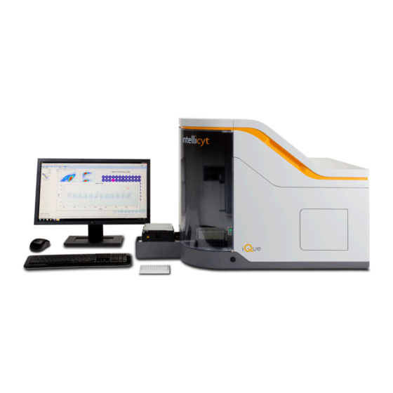
Know the iQue Overview IntelliCyt’s iQue Screener and iQue Screener HD are platforms for screening suspension cells, beads, microbes and ® mixtures. These systems consist of a robotic plate rail with an orbital shaker, robotic plate sampler, detector, and ForeCyt software to design, run, and analyze screening assays. -
Page 24: Specifications
Sensitivity 7 Decade Dynamic Range using Fixed Optics iQue Screener: 96- and 384-Well Microplates, Tubes Sample Formats iQue Screener HD: 384- and 1536-Well Microplates, Tubes Sample Volumes, Sampling Rate 1μL and Higher (no dead volume), 10,000 Objects/Second Plate Processing Speed As Low as 3 Minutes/96-Wells, 12 Minutes/384-Wells Control &... -
Page 25: Fluorescence Channels
Fluorescence Channels The following table lists the configurations of the four fluorescent channels of the iQue Screener in its default laser and filter configuration along with examples of some flourophores that can be used with the iQue. Note that this is not meant to be a comprehensive list of all available fluorophores that work with the iQue. -
Page 26: Variations
Variations There are three variations of the iQue: Variation Distinguishing Features Non-contact sensing 8” probe assembly. Four fluid stations marked Gen 1 iQue S1, S2, S3 and S4. 96- and 384-well plate capable. Contact sensing and piercing probe assembly. Fluid stations labeled Gen 2 iQue Buffer, Markers, Decon, Clean and Water. -
Page 27: Doors Open View
Doors Open View Pump Area Top Door Detector Cover Sampling Area Bottle Drawer Connection Area Sampling Area Door Detector Inlet iQue terminology - 4/26/2013 Shaker Detail View Shaker Deck Gripper Release Lever Gripper (1 of 2) Status Light Cable Guide Plate Rail iQue Hardware Manual: Part Number 10554 Rev C., Getting to Know the iQue... -
Page 28: Sampler Detail View - Gen 1
Sampler Detail View – Gen 1 Sampler Z Arm Probe Locking Outer Probe Adapter Outer Probe Sampler XY Arm Probe Guide Probe Tip Sampler Detail View – Gen 2 Sampler XY Arm Probe Locking Nut Probe Assembly Cover Outer Probe Probe Guide Sampler Z Arm Probe Tip... -
Page 29: Fluid Station View - Gen 1
Fluid Station View – Gen 1 Fluid Station Detail View – Gen 2 iQue Hardware Manual: Part Number 10554 Rev C., Getting to Know the iQue ®... -
Page 30: Top Down View
Top Down View Sheath Filter Sample Area Pass Through Sampler Tubing Tubing Stop Detector Cover Pump Pump Release Trigger Pump Rollers Compression Adjustment Knob Connection Area Pass Through iQue terminology - 4/26/2013 Detector Area Detail View Sheath Pump Excitation Lasers Tubing Clip Waste Pump Tubing Disconnect... -
Page 31: Back View
Back View Ventilation Fans Fuse Compartment Main Power Switch Power Socket Rear Service Panel Computer Connection Manufacturer’s Label iQue terminology - 4/26/2013 System Status Light System Status Light The iQue system status is displayed on the hardware and in the ForeCyt software. The system status light can be one of three colors (green, yellow, or red) that corresponds to the current state of the iQue (ready, warning, and not The iQue system status is displayed on the hardware and in the ForeCyt software. - Page 32 Indicator System Status Description Ready The system is ready to prime, run, or clean The system has warnings that may prevent priming, Warning running, or cleaning but is not faulted Not Ready The system cannot prime, run, or clean due to a fault For detailed messages about the system status press the Show Details button on the Controller console.
-
Page 33: Ique Operation
iQue Operation Introduction The following articles provide detailed instructions for the day-to-day operation of the iQue. Cleanliness and Best Practices Proper start-up, shut-down, and adherence to other best practices are necessary to maximize instrument performance and to minimize clogs and repairs. Please become familiar with these procedures and implement labratory protocols to ensure that the following best practices are followed. - Page 34 THIS PAGE INTENTIONALLY LEFT BLANK iQue Hardware Manual: Part Number 10554 Rev C., iQue Operations: Cover Page ®...
-
Page 35: Ique Fluids
Decontamination Concentrate Part #: 90077 A mildly acidic and surfactant solution used to Cleaning Solution 200 mL water* + 3 mL pipetted IntelliCyt neutralize the decontamination solution and Part #: 90079 Cleaning Concentrate clean the system. For all iQue fluids, HPLC reagent grade filtered, distilled water (0.22 μm filter), or equivalent is recommended. Unfiltered distilled water is acceptable. -
Page 36: Filling The Bottles
Use only IntelliCyt approved fluids in the iQue screener. Use of unapproved fluids CAUTION can damage the instrument. In particular, the use of sheath fluid or cleaners designed for other flow cytometers as well as the use of household bleach or other caustic agents are strictly prohibited. -
Page 37: Filling The Troughs
Close the bottles and place them back in the drawer. Reconnect the fluid lines, matching the color of the connector to the color of the bottle. NOTE Close bottles securely, but do not over-tighten. The iQue screener is a non- pressurized system. Carefully close the drawer making sure that the bottle lines are not pinched. -
Page 38: A Note On Fluid Fill Level
NOTE Dirty fluid troughs are a common source of contamination. Replace troughs as needed and always use fresh fluids. A Note on Fluid Fill Level With a Gen 2 probe, the probe depth in the fluid stations is pre-set. Fluid stations should be filled to approximately 14 mm above the top of the “V”... -
Page 39: Daily Startup
Daily Startup Overview This procedure explains how to perform a proper daily startup. This entire procedure should take no longer than 20 minutes assuming the system was shut down properly and all the required fluids are prepared. Referenced Procedures • Fluidics Maintenance •... - Page 40 NOTE If the iQue detector takes longer than 5 minutes to reach the Ready state, this indicates either an improper shutdown or possible fluidics issues such as clogging. Perform Daily QC as described in the Daily QC procedure. Attach the sampler tubing to the Detector Inlet. Click Prime and allow the system to prime for 3 minutes.
-
Page 41: Daily Qc
Daily QC Overview Running daily quality control is highly recommended for the iQue Screener. A daily QC check not only ensures that system performance is within specifications, but is also a useful diagnostic tool if issues arise. IntelliCyt makes the QC process easy by providing reagents and pre-configured analysis templates. -
Page 42: Creating The Daily Qc Experiment
Click the Browse button and choose the Daily QC template that matches the bead lot being used. NOTE Contact IntelliCyt Tech Support to obtain the latest Daily QC Template for any specific bead lot. Give the Daily QC experiment a name and click OK. -
Page 43: Interpreting The Water Test
Interpreting the Water Test The Water Test is a gauge of system cleanliness. Use the following guidelines to interpret the results. Event Count for 2 Minute Water Run System Clogged 1–250 Clean 251–1000 Operational > 1000 Needs Cleaning If the system appears to need cleaning see Standard Cleaning Procedures. -
Page 44: Running The 6 Peak Beads Test
Running the 6 Peak Beads Test Perform a Backflush by clicking the Clean button on the controller console, choosing the Backflush option, and following the wizard. Place the 6 Peak Bead sample on the detector inlet. Select the 6 Peak Beads tube in the experiment. Click Run. -
Page 45: Interpreting The 6 And 8 Peak Bead Tests
On each plate, switch to the Metrics tab and note the values of the Test Metrics. For each Metric, 1 means pass and 0 means fail. If any of the tests fail, contact IntelliCyt Tech Support. Passing 6 Peak Beads QC Metric iQue Hardware Manual: Part Number 10554 Rev C., iQue Operations: Daily QC... - Page 46 THIS PAGE INTENTIONALLY LEFT BLANK iQue Hardware Manual: Part Number 10554 Rev C., iQue Operations: Daily QC ®...
-
Page 47: Daily Shutdown
Daily Shutdown Overview This procedure explains how to properly shut the iQue down at the end of the day. This procedure can be initiated and left to run unattended. It takes approximately 45 minutes to complete. Steps Click Clean in the ForeCyt Controller Console window. In the Clean wizard, select Clean Type = Daily Clean and check Shutdown after Clean and then click Next. - Page 48 THIS PAGE INTENTIONALLY LEFT BLANK iQue Hardware Manual: Part Number 10554 Rev C., iQue Operations: Daily Shutdown ®...
-
Page 49: Ique Maintenance
iQue Maintenance Introduction The following chapters provide detailed instructions for the routine maintenance procedures required to keep the iQue running. Cleanliness and Best Practices Regular cleaning and maintenance are necessary to maximize instrument performance and to minimize clogs and repairs. Please become familiar with these procedures and implement labratory protocols to ensure that the following best practices are followed. - Page 50 THIS PAGE INTENTIONALLY LEFT BLANK iQue Hardware Manual: Part Number 10554 Rev C., iQue Maintenance: Cover Page ®...
-
Page 51: Recommended Maintenance Schedule
Recommended Maintenance Schedule Overview iQue Maintenance involves several procedures that need to be performed regularly. What follows are guidelines for typical usage scenarios. Moderate Usage is defined as less than 15 hours of run time per week. Heavy Usage is defined as more than 15 hours of run time per week. - Page 52 THIS PAGE INTENTIONALLY LEFT BLANK iQue Hardware Manual: Part Number 10554 Rev C., iQue Maintenance: Recommended Maintenance Schedule ®...
-
Page 53: Standard Cleaning Procedures
Standard Cleaning Procedures Overview The ForeCyt software supports several standard cleaning procedures. This article explains what each one does and when to use it. All of the standard cleaning procedures are accessed by clicking the Clean button and using the Clean wizard. -
Page 54: Daily Clean
Daily Clean The Daily Clean is performed daily, typically at the end of the day during the shutdown procedure. Unlike the other cleaning cycles, this clean is done with the tubing attached and it cleans the entire fluidics path from probe to detector. In the default configuration (recommended) the Daily Clean runs 5 minutes of... -
Page 55: Monthly Clean
Monthly Clean The Monthly Clean is a special cleaning procedure that should be done once a month. This clean works by filling the flow cell with an enzymatic cleaner and letting it soak overnight. To perform the Montly Clean, choose Monthly Clean for the Clean Type. Place a tube of Extended Flow Cell Cleaner on the detector inlet and follow the wizard instructions. - Page 56 THIS PAGE INTENTIONALLY LEFT BLANK iQue Hardware Manual: Part Number 10554 Rev C., iQue Maintenance: Standard Cleaning Procedures ®...
-
Page 57: Changing The Probe And Tubing
As the iQue runs, the main sample tubing is worn by the rollers of the peristaltic pump. To ensure proper sample collection, IntelliCyt recommends that the probe and tubing assembly be changed after 15 hours of usage. This article describes the proper way to perform this procedure. - Page 58 Detach the Old Tubing In the Detector area, disconnect the tubing from In the Pump area, press the pump head release the detector inlet. trigger to unlock the pump head. Draw the loose end of the tubing up out of the Working in the main sampling area, draw the Detector area tubing through the sampler area pass-through.
-
Page 59: Replacing The Probe: Gen 1 Probe Assembly
Replacing the Probe: Gen 1 Probe Assembly Lift the probe and tubing assembly out of the Unscrew the brown fitting from the probe holder upper probe guide. assembly. Pull the inner probe out of the probe holder and discard, using appropriate disposal container. Carefully insert a new inner probe into the probe holder and finger tighten the brown fitting. -
Page 60: Attaching The New Tubing
Carefully insert the probe from the new probe Screw the black fitting into the probe holder and and tubing assembly into the probe holder. finger tighten. Do not use a tool to tighten. Attaching the New Tubing Thread the new tubing back through the sampler area passthough into the pump area. Route the tubing into the pump head as shown. - Page 61 Feed the tubing down through the hole leading into the detector area. Re-attach the tubing to the detector inlet. iQue Hardware Manual: Part Number 10554 Rev C., iQue Maintenance: Changing the Probe and Tubing ®...
-
Page 62: Re-Calibrating Deck Height
Re-Calibrating Deck Height Whenever the probe and tubing is changed, it is important to re-calibrate the deck height to account for any possible variation in probe lengths. At the end of the Change Probe and Tubing wizard, a prompt will appear: Click Yes and follow the Deck Height Calibration wizard. - Page 63 Pump Head Tension Screw Slowly loosen the screw by turning in a counterclockwise motion until the sample slugs appear to stop. Then slowly tighten the screw until the movement towards the iQue detector resumes. Note that changes in screw tension can take up to 30 seconds to appear. Make small adjustments and wait to see their effect. Loosen the screw again very slowly until sample just starts to stop.
- Page 64 THIS PAGE INTENTIONALLY LEFT BLANK iQue Hardware Manual, iQue Maintenance ®...
-
Page 65: Fluidics Maintenance
Fluidics Maintenance Overview The iQue detector has several parts that are designed to be regularly replaced in order to keep the system running in optimal condition. These include various filters as well as the peristaltic pump tubes. Frequency At a minimum, fluidics maintenance should be performed every two months (bi-monthly). In a heavy usage situation, this maintenance may need to be performed more frequently. -
Page 66: Removing The Optics Cover
Removing the Optics Cover Prior to performing the first two steps of the fluidics maintenance procedure, the optics cover must be removed from the detector. It is not necessary to shut down the detector before doing this as the optics cover contains an interlock that automatically keeps the system from running when the cover is off. -
Page 67: Changing The In-Line Sheath Filter
Changing the In-Line Sheath Filter Locate the in-line sheath filter on the left of the detector. In-line Sheath Filter Untighten the Luer lock fittings. Remove and dispose of the old filter. Remove the new in-line sheath filter from its package and write the current date on the filter with a permanent marker. -
Page 68: Changing The Detector Peristaltic Tubes
Changing the Detector Peristaltic Tubes Locate the sheath and waste pumps on the top of the detector. Sheath Pump Waste Pump Disconnect the Luer locks to the tubing on the outside of the peristaltic pumps by unscrewing them. The blue tubing is connected to the sheath pump and the red tubing to the waste pump. iQue Hardware Manual: Part Number 10554 Rev C., iQue Maintenance: Fluidics Maintenance ®... - Page 69 Squeeze the grip marks on the pump element retainer clip and slide the clip to remove it. Slide the Luer lock fittings laterally out of the grooves holding them to the pump head and remove the peristaltic tubing assembly. Discard the old tubing assembly. Remove the new peristaltic tube assembly from its package and write the current date on the side with a permanent marker.
- Page 70 Impinging Correct Cross Slotted Correct Kinked Correct Examples of improperly and properly installed peristaltic tube assemblies iQue Hardware Manual: Part Number 10554 Rev C., iQue Maintenance: Fluidics Maintenance ®...
-
Page 71: Changing The Bottle Filters
Changing the Bottle Filters Remove the Sheath, Decontamination Fluid and Cleaning Fluid bottles from the bottle drawer. Carefully remove the lid from each bottle. Unscrew the three filters and discard them in the same way as a biological sample. Locate the new sheath filter. This is the large disk filter. Install the new sheath filter with the printing side down. - Page 72 THIS PAGE INTENTIONALLY LEFT BLANK iQue Hardware Manual: Part Number 10554 Rev C., iQue Maintenance: Fluidics Maintenance ®...
-
Page 73: Wetting Procedure
Place a 5 mL tube containing 3 mL of 70% reagent grade ethanol on the detector inlet. Create a new Test Tube experiment. On the Protocol tab, set the IntelliCyt Cytometer Speed to Fast Set The Test Tube Time Limit to 10 minutes. -
Page 74: Running Water On Fast For 10 Minutes
Running Water on Fast for 10 minutes Place a 5 mL tube containing distilled water on the detector inlet. Add another test tube to the experiment and set the Test Tube Time Limit to 10 minutes. Run the experiment. Backflush Click the Clean button. -
Page 75: Managing Plate Models
Managing Plate Models Overview For different experiments, researchers use different kinds of plates with different shapes, depths and characteristics: v-bottom vs. round-bottom vs. flat bottom; shallow vs. deep; circular vs. square. This article discusses how to set up and maintain a “library” of plate models that can be used when defining an experiment protocol. Understanding Plate Model Calibration The plate model controls the sampling depth. -
Page 76: Plate Model Selection Is Part Of Protocol
Plate Model Selection is Part of Protocol Each plate on each experiment has a set of Protocol settings that control how the plate is run. On the Sample section, there is a field for Plate Model. This is where the plate model is selected: By default, the system comes with only two plate models listed: the Generic 96 Well Plate and Generic 384 Well Plate models. - Page 77 In the Manage Plate Models screen, click Add and enter the name, manufacturer and type for the new plate model. Click Save. A confirmation prompt will appear for callibrating the plate model. Click Yes. Follow the instructions in the Plate Model Calibration wizard. Once the plate model is calibrated, it will show up in the Manage Plate Models screen and will be available as a choice in the Experiment Protocol.
-
Page 78: Calibrating A Plate Model: Gen 1 Probe Assembly
Calibrating a Plate Model: Gen 1 Probe Assembly Click Device > Manage Plate Models. Highlight the Plate Model to be calibrated and click Calibrate. This will bring up the Plate Model Calibration wizard. Follow the wizard instructions carefully. Place the plate being calibrated on the deck and click Next. Use the Vertical Movement controls to lower the probe to the proper sampling depth. -
Page 79: Calibrating A Plate Model: Gen 2 Probe Assembly
Calibrating a Plate Model: Gen 2 Probe Assembly Click Device > Manage Plate Models. Highlight the Plate Model to calibrate and click Map. This will bring up the Plate Model Mapping wizard. Follow the wizard instructions carefully. Place the plate being calibrated on the deck and click Next. The next step in the wizard allows for the configuration of an optional X-Y offset. -
Page 80: Optional X-Y Offset
Optional X-Y Offset The normal sample position is from the center of the well. When using flat bottom plates, however, the vortexing action of the shaker causes sample to accumulate on the edges of the well so it becomes necessary to sample from the side or corner of the well. -
Page 81: Setting The Default Plate Model For Each Plate Type
Setting the Default Plate Model for each Plate Type When creating a blank experiment (i.e., not from a template) a default plate model for the format (96 or 384 well) is chosen. To customize which plate model is used as the default follow the steps below. Click Device >... - Page 82 THIS PAGE INTENTIONALLY LEFT BLANK iQue Hardware Manual: Part Number 10554 Rev C., iQue Maintenance: Managing Plate Models ®...
-
Page 83: Clog Prevention And Management
The use of cleaning cycles between plates and within a plate as needed. Recommended Sample Concentrations For rapid sampling using common suspension cell lines, IntelliCyt recommends a final cell concentration of between 1-3 x10 cells/mL. Cell densities that are higher or lower are possible, but should be tested and optimized. -
Page 84: Rinsing During A Plate
Rinsing During a Plate It is possible to configure a rinse at regular intervals while sampling wells on a plate. To configure a rinse, follow these steps: In the Rinse section of the Protocol tab, check the box to Enable Probe Rinse and set the amount of wells after which a rinse should occur. -
Page 85: Cleaning During A Plate
Cleaning During a Plate It is possible to configure a “mini-clean” to happen at various intervals within a plate. To configure a clean within the plate, follow these steps: In the Rinse section on the Protocol tab, check the box to Enable Probe Rinse and set the amount of wells after which a clean should occur. - Page 86 Repeat again selecting Water for 2000 ms (2 seconds): Repeat one last time selecting Buffer for 1000 ms (1 second): This will create a standard Decon-Clean-Rinse mini-clean. The purpose of the final rinse in Buffer is to re-prime the line and make sure that proper pH and osmality are maintained prior to running the next sample. iQue Hardware Manual: Part Number 10554 Rev C., iQue Maintenance: Clog Prevention and Management ®...
-
Page 87: Using The Clog Detection Feature
Using the Clog Detection Feature By default, every new iQue Experiment has the Clog Detection feature enabled in the Protocol of every plate: This is a software feature that works by monitoring the event rate during data acquisition. If the event rate fall below a certain threshold for longer than expected, taking into account shakes and cleans which naturally lower the event rate, then the clog detector triggers a warning: Click Yes to stop the run immediately. -
Page 88: Signs And Symptoms Of Clogging
Troubleshooting a Clog The first step in troubleshooting a clog is to contact IntelliCyt tech support so that we may help assess the seriousness and nature of the problem and recommend remediation steps. These may include performing standard cleaning procedures such as the Backflush, Unclog, Quick Clean and Long Clean procedures. -
Page 89: Special Topics
Introduction This following articles provide detailed instructions for handling special situation that may arise with an iQue. It is strongly recommended that iQue users contact IntelliCyt Tech Support prior to performing any of these procedures. Safety Always wear appropriate safety attire, such as protective gloves and eye wear when performing operations where contact with chemical or biological agents is possible. - Page 90 THIS PAGE INTENTIONALLY LEFT BLANK iQue Hardware Manual: Part Number 10554 Rev C., Special Topics: Cover Page ®...
-
Page 91: First-Time Startup Checklist
First-Time Startup Checklist Overview This is a quick-start guide for first time startup. It should be used the very first time an iQue is installed and started and also when re-commissioning an instrument that has been idle or setting an instrument up after it has been moved. - Page 92 THIS PAGE INTENTIONALLY LEFT BLANK iQue Hardware Manual: Part Number 10554 Rev C., Special Topics: First-Time Startup Checklist ®...
-
Page 93: Long-Term Shutdown Checklist
Long-Term Shutdown Checklist Overview Use this procedure when shutting down the iQue prior to a pause in operation of more than a week. Referenced Procedures • Standard Cleaning Procedures Steps Perform the Daily Clean as shown in Standard Cleaning Procedures but DO NOT select the Shutdown Detector option. - Page 94 THIS PAGE INTENTIONALLY LEFT BLANK iQue Hardware Manual: Part Number 10554 Rev C., Special Topics: Long-Term Shutdown Checklist ®...
-
Page 95: Connecting Ique Power And Data Cables
Each iQue comes with an Uninterruptible Power Supply (UPS). This UPS is required equipment and the instrument’s CE Mark is invalid unless the iQue Screener power connection is connected to the UPS. The iQue comes with one of two UPS units depending on the power system of the target locale. -
Page 96: Connecting Ique Power Cables
Connecting iQue Power Cables Plug the UPS into a grounded socket. Check the UPS for warnings or alarms that indicate faulty or inadequate power or a defective UPS batter. Plug the iQue main power into one of the protected and battery backed up sockets on the UPS as shown in the diagram below. -
Page 97: 110V Power And Data Connection Diagram
110V Power and Data Connection Diagram 220V Power and Data Connection Diagram iQue Hardware Manual: Part Number 10554 Rev C., Special Topics: Connecting iQue Power and Data Cables ®... - Page 98 THIS PAGE INTENTIONALLY LEFT BLANK iQue Hardware Manual: Part Number 10554 Rev C., Special Topics: Connecting iQue Power and Data Cables ®...
-
Page 99: Moving An Ique
Described the procedure for safely moving an iQue from one location to another within the same lab or building. This does not include instructions for packaging the iQue for shipment. If the need to package and ship an iQue arises, contact IntelliCyt Tech Support. Referenced Procedures Standard Cleaning Procedures •... -
Page 100: Moving The Instrument
Moving the Instrument Prepare the destination location. Make sure there is adequate space, ventilation and power. Avoid shocks to prevent disturbing the optics. Use a cart with cushioned tires if possible. Alternatively, place the unit on a thick piece of foam. Be gentle when setting the system down. -
Page 101: Re-Calibrating Deck Positions
Required Materials The iQue Screener comes with a special Calibration Tool which is required for recalibrating deck positions. One side of the tool is for calibrating the well positions used for sampling a plate. The other is side is used for calibrating fluid station positions. -
Page 102: Gen 1 Vs Gen 2 Calibrations
A confirmation prompt will appear warning that this procedure that needs to be done with the assistance of a technician. If this procedure has not been performed previously, contact IntelliCyt Tech Support for assistance. Click OK. iQue Hardware Manual: Part Number 10554 Rev C., Special Topics: Re-Calibrating Deck Positions... -
Page 103: Deck Height Calibration: Gen 1 Probe
This brings up the Calibrate iQue screen which contains links for the various deck locations that can be calibrated. Note that for a Gen 1 iQue, there is no Testing Point and the first menu item only says Calibrate Deck Height. Deck Height Calibration: Gen 1 Probe The Calibrate Deck Height wizard begins with this screen: iQue... - Page 104 Use the vertical movement controls to lower to probe until it just touches the shaker deck surface as shown: Probe just touching deck Be sure that the probe itself is not sliding up in the guide. If the probe has been pushed upward, the deck height calibration value will be incorrect (too low) which will cause the probe to strike the bottom of the plate during sampling.
-
Page 105: Deck Height Calibration: Gen 2 Probe
The contact sensing probe will descent and measure the deck height. CAUTION Proper test point calibration is essential for proper iQue functioning. Do not attempt this procedure without assistance from IntelliCyt Tech Support or proper training. Calibrate Well Plate Coordinates Click Calibrate Well Plate Coordinates and carefully follow the wizard instructions. -
Page 106: Calibrate Fluid Stations And Depths
Follow the wizard to locate the four calibration points on the deck, Top Left, Top right, Bottom Left and Bottom Right. These points must be defined exactly to ensure proper sampling, particularly in higher density formats. Note that during Well Plate calibration, depth is not recorded. Sampling depth is a function of deck height and Plate Model. - Page 107 Move the probe to a position over each one of the test points in turn until all the wizard steps are completed. iQue Hardware Manual: Part Number 10554 Rev C., Special Topics: Re-Calibrating Deck Positions ®...
- Page 108 THIS PAGE INTENTIONALLY LEFT BLANK iQue Hardware Manual: Part Number 10554 Rev C., Special Topics: Re-Calibrating Deck Positions ®...
- Page 109 IntelliCyt Tech Support IntelliCyt® Corporation 9620 San Mateo NE Albuquerque, NM 87113 USA www.intellicyt.com Telephone: 505-345-9075 opt 2 E-mail: support@intellicyt com...
Need help?
Do you have a question about the iQue SCREENER and is the answer not in the manual?
Questions and answers