Table of Contents
Advertisement
Quick Links
YMGI, Engineered Comfort Products for A Sustainable and Efficient Green World!
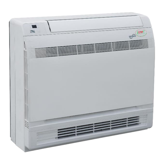
Multi Variable Air Conditioners Console Indoor Type Unit
VRFI-07EL-D2B(55)5
VRFI-09EL-D2B(55)5
VRFI-12EL-D2B(55)5
VRFI-18EL-D2B(55)5
Thank you for choosing this YMGI product. Please read the user's manual carefully before installation/operation and retain for
your records and future reference. If you need a replacement copy, please contact your local agent or visit www.ymgigroup.com
to download a current electronic version.
This product is designed and manufactured to be free from any defects in material and workmanship during normal use and
maintenance. Installation, operation, maintenance and repairs must follow all standards and professional practices for regular
cooling and heating equipment, such as NEC, State, or Local Codes and all related documents/manuals provided by YMGI.
Failure to follow and adhere to all codes and documentation can cause damage to equipment, property or even personal injury.
Installer: Must be currently licensed/certified HVAC technicians only. Must Read the manual and all provided documents prior
to installation. Complete and fill out all required information on the Warranty Registration Card.
User: Retain this manual and all supplied documents for your records and future reference.
Servicer: Use this manual for information concerning servicing and maintenance of this product.
Only qualified technicians should install and service this equipment. The installation, startup, operation and servicing of this
equipment can be hazardous and requires a HVAC professional who has been trained, licensed and certified. Installations,
adjustments or any equipment alterations done by an unqualified person could result in serious injury and even death. When
working on the equipment, observe all precautions in the provided documents, on the tags, stickers, and labels that are attached
to or placed on the equipment.
NOTICE
SAFETY WARNING
1
Advertisement
Table of Contents

Related Manuals for YMGI VRFI-07EL-D2B(55)5


Summary of Contents for YMGI VRFI-07EL-D2B(55)5
- Page 1 VRFI-12EL-D2B(55)5 VRFI-18EL-D2B(55)5 Thank you for choosing this YMGI product. Please read the user’s manual carefully before installation/operation and retain for your records and future reference. If you need a replacement copy, please contact your local agent or visit www.ymgigroup.com to download a current electronic version.
-
Page 2: Table Of Contents
Limited Product Warranty ............................8 Limited Product Warranty Registration Card ....................... 9 Why Does YMGI Group Require Installation and Service to Be Performed 100% By Currently Licensed or Certified HVAC Technicians/Contractors ..............10 Suggestions to Aid You in Hiring an HVAC Contractor ..................... 10 Safety Precautions .............................. -
Page 3: Introduction
Refrigerants that contain Chlorine, Fluorine and Carbon (CFCs) and those containing Hydrogen, Chlorine, Fluorine and Carbon (HCFCs), may affect the ozone layer. Not all refrigerants have the same potential impact on the environment. YMGI Group advocates for the responsible handling of all refrigerants including industry replacements for CFCs such as HCFCs and HFCs. - Page 4 All NEC, state, local codes and installation instructions must be followed for all units, otherwise, the unit warranty will be void and could result in serious damage to people or property. YMGI Group is not responsible for any damage or loss due to Do-It-Yourself(DIY), self-installation or any improper installation, operation, service or natural disasters of any kind.
-
Page 5: Note From Ymgi - Must Read
YMGI Group is the MEDIA AUTHORITY: YMGI Group, located in O'Fallon, MO 63366 is the author of all media produced for its products and is the only party able to give any additional explanation for any data, definitions and or descriptions found within any of its media, including but not limited to YMGI product brochures, manuals, pamphlets, catalogs, and videos. - Page 6 With the information provided above, you will know some things to look for and questions you can ask. If at any time you feel there may be an issue with the installation, please have your technician contact YMGI at...
-
Page 7: Installing Technician/Contractor's Responsibilities
Make sure you have all the materials you need to properly, completely and correctly finish the installation. The YMGI units and accessories may be just a portion of what you will need for the project. When support issues arise, remember YMGI employees and YMGI distributors/sales, dealers and agents are not installers and may only provide suggestions. -
Page 8: Limited Product Warranty
At no time does YMGI Group warrant labor cost of any type. Warranty will start from the date of a successful installation at the original installation location, or 90 days as of original shipping date from YMGI Group, whichever comes first. -
Page 9: Limited Product Warranty Registration Card
YMGI Technical support the exact part(s) needed to fix the problem(s). 2. YMGI will check the customer's warranty filing. There will be no charge for Parts with a validated and approved warranty. Any Parts needed for warranties that have not been validated and approved or have an invalid warranty filing (resulting in an unapproved warranty request), will be charged accordingly. -
Page 10: Why Does Ymgi Group Require Installation And Service To Be Performed 100% By Currently Licensed Or Certified Hvac Technicians/Contractors
6. Some contractors/technicians may not feel comfortable about installing equipment that has been purchased by someone other than themselves. You can contact YMGI directly to check and see if there are contractors in your area who have installed our products or any similar products. -
Page 11: Safety Precautions
YMGI Group recommends that only properly trained and authorized personnel be allowed to repair or service the unit. Improper repairs or servicing can result in electric shock or fire hazards. Please contact YMGI Group if you need help locating a qualified repair or service technician. -
Page 12: Installation Of Indoor Unit
Installation of the Indoor Unit Selection of The Installation Location Select a location where cool air can be distributed throughout the room. Select a location where condensation water can be easily drained. Select a location on the wall or floor that can support the weight of the indoor unit. ... - Page 13 Location for securing the installation pane. Schematic drawing of hooks.
- Page 14 Refrigerant Piping Drill a hole (65mm or 2-9/16 inches in diameter) in the spot indicated in the illustration below. The location of the hole is different depending on which side of the unit the pipe is taken out. ...
- Page 15 Drain Piping For the drain pipe, use commercially available rigid polyvinyl chloride pipe general VP 20 pipe with an outer diameter of 26mm or 1 inch and an inner diameter of 20mm or 13/16 inch. The drain hose with an outer of diameter 18mm or 3/4 inch at connecting end and is 220mm or 8-11/16 inches long, is supplied with the indoor unit.
- Page 16 For Moldings Remove the Side and Top Casings. (Remove the slit portions on the bottom frame, if necessary, using nippers.) For Side Piping Remove the Side and Top Casings. 1. Remove the 9 screws securing the casings. 2. Remove the upper casing by depressing the 2 tabs. 3.
- Page 17 Installation For floor installations, secure the unit to the floor using 6 screws. (Do not forget to secure the unit to the wall.) For wall installations, secure the mounting plates using 4 screws and the indoor unit using 4 screws. The mounting plates must be installed on a wall capable of supporting the entire weight of the indoor unit.
- Page 18 Do not use mineral oil on the flared part. Prevent mineral oil from getting into the system as this would reduce the life expectancy of the units. Never use piping that has been used for previous installations. Only use parts which are delivered with the unit. ...
- Page 19 Selection of Copper and Heat Insulation Materials When using commercial copper pipes and fittings, observe the following: Insulation material: Polyethylene foam: heat transfer rate:0.041 to 0.052W/mK (0.035 to 0.045kca/(mh℃ ) Refrigerant gas pipe’s surface temperature reaches 110℃ (230℉ ) max.. Choose heat insulation materials that will withstand this temperature.
- Page 20 Insulate the joint of the pipes and secure. Incomplete or improper insulation may lead to condensate leakage. Push the pipe inside to prevent it from placing undue force on the front grille. Connecting the Drain Hose Insert the supplied drain hose into the socket of the drain pan. ...
- Page 21 The power of every indoor unit should be on its own circuit/power supply. Do not use tapped wires, stranded wires, extension cords, or starburst connections, as they may cause overheating, electrical shock, or fire. Do not use locally purchased electrical parts inside the unit. (Do not branch the power for the drain pump, etc., from the terminal block.) Doing so may cause electric shock or fire.) 1.
-
Page 22: Component Identification
Install the drainage pipe (1). For correct draining, the drain hose should be slanted downward. (2). Do not wrench or bend the drain hose or place the open end into water. (3). Wrap with heat resistant material when connecting the longer drainage tube though to the indoor unit. Install the Refrigeration Pipes Connect the refrigeration pipes with the two relative leading pipes, tighten the nut on the refrigeration pipes securely. -
Page 23: Working Temperature Range
This switch is useful when the remote controller is missing. 15. Signal receiver: a. It receives signals from the remote controller. b. When the unit receives a signal, you will hear a short beep. c. Settings change the beep. 16. -
Page 24: Remote Controler
Remote Controller YAP1F Button Name and Function Introduction Button name Function ON/OFF Turn on or turn off the unit TURBO Set turbo function MODE Set operation mode Set up & down swing status I FEEL Set I FEEL function Switch temperature displaying type on the unit’s display TEMP Set health function and air function LIGHT... - Page 25 Preparation Before Operation When using the remote controller for the first time or after replacing the batteries, please set the time of the system according to current time in the following steps: 1. Pressing CLOCK button, is blinking. 2. Pressing button, the clock time will increase or decrease rapidly.
- Page 26 Setting up and down SWING: 1. Under simple SWING status, press button to adjust up and down SWING status; 2. Under fixed-angle SWING status, press button to adjust up and down SWING angle circularly as below: Note: Operate continuously left and right SWING in 2 seconds, swing states will change accordingly to above- mentioned order, or switch closed state and state;...
- Page 27 11. Setting sleep function: In unit on status, press SLEEP button to turn on or turn off sleep function. When is displayed, the sleep function is on. When is not displayed, the sleep function is off. Notes: Sleep function cannot be set in auto and fan mode; When turning off the unit or switching mode, sleep function is cancelled.
-
Page 28: Maintenance Method
4. Absence function: In unit on status and under heat mode, press CLOCK and TEMP buttons simultaneously to enter absence function. Temperature displaying zone displays 8 and Press CLOCK and TEMP button simultaneously again to exit absence function. Temperature displaying zone resumes previous display and is not displayed. - Page 29 Front Panel 1. Open the front panel. 2. Remove the air filter. Slide the two stoppers on the left and right sides inward until they click. 3. Remove the front panel. Remove the string. Allow the front panel to fall forward and then you can remove it. 4.
- Page 31 Filters 1. Open the front panel. 2. Remove the air filter. I. Press the tabs down slightly on the air filter frame, located on the right and left, while pulling air filter away from the unit. 3. Take off the Titanium Apatite Photocatalytic Air-Purifying Filter. I.
- Page 32 6. Wash the air filters with water or clean them with vacuum cleaner If the dust does not come off easily, wash them with a neutral detergent and lukewarm water, then allow the filter to air dry thoroughly in a place not exposed to direct sunlight. It is recommended to clean the air filter every week.
-
Page 33: Function Description
Function Description of Functional Dial Switch S7 1. The 3-bit dial switch must be set before energizing the main board and it determines running state of indoor unit. 2. Function of it is as follow: Dial switch Silk screen Function Dial ON Dial OFF Selection of memory mode:... -
Page 34: Recommended Tools For Installation
Service Center When the following phenomena appeared, stop operating immediately, turn off the main power supply of unit and contact qualified service center or technician to check the unit. Harsh sound heard when running. The fuse or protector trips frequently. ... -
Page 35: User Notes And Installation/Service/Maintenance Notes
Please list any questions or issues you may have with this unit: Date Noes Asked Your Did You Ask YMGI Technician for Help? Tech. for Help? USER NOTES Please list any questions or issues you may have with this unit:... - Page 36 SERVICE / MAINTENANVE NOTES Please list any questions or issues you may have with this unit: Technician’s Company Name, Technician Date Contents of Service / Maintenance Name, Phone & HCAC License # After-Sales/Service When having quality or other problems when purchasing the air conditioner, please contact the local service center.
Need help?
Do you have a question about the VRFI-07EL-D2B(55)5 and is the answer not in the manual?
Questions and answers