Table of Contents
Advertisement
Quick Links
Advertisement
Table of Contents

Subscribe to Our Youtube Channel
Related Manuals for White International DP 81


Summary of Contents for White International DP 81
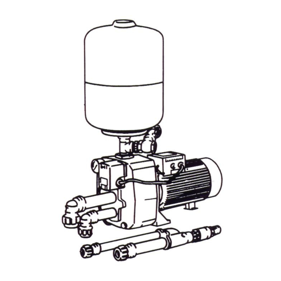
- Page 1 INSTALLATION AND OPERATING MANUAL FOR DAB DEEP WELL JET PUMPS...
-
Page 2: General Data
0°C to +40°C for other uses - Maximum ambient temperature: +40°C - Maximum operating pressure: DP 81 - DP 100 6 bar (600 kPa) DP 151 - DP 251 8 bar (800 kPa) - Installation: fixed in a horizontal position... - Page 3 DEEP WELL AND SHALLOW WELL CONVERTABLE 151 - 251 DP 81 – DP 100 Warning: Pumps must not operate below their minimum “Delivery Pressure” as shown in the accompanying charts, as pumps will cavitate (loss of prime, air in water, fluctuating pressure gauge and extra pump noise are indications of cavitation), causing damage to pump components including bearings.
- Page 4 DP 151 – 251 Warning: Pumps must not operate below their minimum “Delivery Pressure” as shown in the accompanying charts, as pumps will cavitate (loss of prime, air in water, fluctuating pressure gauge and extra pump noise are indications of cavitation), causing damage to pump components including bearings. E.g.1.
-
Page 5: Preliminary Considerations
PRELIMINARY CONSIDERATIONS Location Pump can be located at the bore or well, or can be offset some distance away from the water source. For best performance, the pump should be located as close as possible to the water source. Ventilation, cover and drainage must be provided to prevent damage from moisture to the motor and switches if fitted. -
Page 6: Installation
Do not use piping of sizes smaller than those listed in Chart 1, or pump will not operate correctly. Chart 1 Pipe Sizes Required between Water Source and Pump Distance: DP81 DP100 DP151 DP251 Water to Suction Pressure Suction Pressure Suction Pressure Suction Pressure Pump 0-30m 32 mm... - Page 7 Note: Illustrated parts list at end of this manual. Injector Kit Assembly All threaded joints should be sealed appropriately either by Teflon tape or approved sealant. Note: The entire system must be air and water tight for efficient operation. Screw venturi into injector body. Assemble poly pipe pieces and poly end connectors onto injector body,...
-
Page 8: Electrical Connection
Water to Pump Piping For pipe size recommendations refer to Chart 1 on page 6. Always seal pipe ends during installation to stop debris entering the drive and suction pipes, as blockages in the injector body and jet will seriously affect performance. Add sufficient pressure (drive) pipe and suction pipe to submerge the injector 3 to 5 metres below the pumping water level, making certain that the non-return valve plus strainer (foot valve) are at least 2 metres from the bottom of the bore. - Page 9 START UP Check motor shaft rotation. Before power is connected and pump started, it must be checked that the rotating parts turn freely. For this purpose remove the fan cover from its seat in the motor end cover. Insert a screwdriver in the notch on the motor shaft from the ventilation side. If there is a blockage, turn the screwdriver, tapping it gently with a hammer.
- Page 10 If fitted with a pressure switch, adjust to the required pressures. Cut in pressure must not be lower that the minimum drive pressure. If the control valve is opened too far, pump damaging cavitation will occur, and will be noticeable by cavitation noise and pressure fluctuations.
-
Page 11: Troubleshooting
TROUBLESHOOTING FAULT CHECKS (possible cause) REMEDY 1. The motor does not start A. Check the electric connections. and makes no noise. B. Check the motor is live. C. Check the protection fuses. C. If they are burnt out, change them. N.B. If the fault is repeated immediately, this means that the motor is short cycling.
Need help?
Do you have a question about the DP 81 and is the answer not in the manual?
Questions and answers