Table of Contents
Advertisement
Vislink, Waterside House, Earls Colne Business Park, Colchester, Essex, CO6 2NS, UK
Telephone: +44 (0)1442 431300 ● Facsimile: +44 (0) 1494 775356 ● Email: sales@vislink.com ● Website: www.vislink.com
Company Registered in England & Wales no. 10523708 ● VAT registration no. GB 260 012 169
Registered Office: Waterside House, Earls Colne Business Park, Colchester, Essex, CO6 2NS, UK
Advertisement
Table of Contents

Related Manuals for Vislink FCDT-ASSY-7002


Summary of Contents for Vislink FCDT-ASSY-7002
- Page 1 Vislink, Waterside House, Earls Colne Business Park, Colchester, Essex, CO6 2NS, UK Telephone: +44 (0)1442 431300 ● Facsimile: +44 (0) 1494 775356 ● Email: sales@vislink.com ● Website: www.vislink.com Company Registered in England & Wales no. 10523708 ● VAT registration no. GB 260 012 169...
- Page 2 The information contained in this manual remains the property of Vislink and may not be used, disclosed or reproduced in any other form whatsoever without the prior written permission of Vislink. Vislink reserves the right to alter the equipment and specification appertaining to the equipment described in this manual without notification.
- Page 3 Included Grass Valley RS422 Multiplexing cable Included G Valley OCP400 Multiplex cable and defined the Non-Multiplex cable in Table 7-2. 14/09/2017 Corrected Section 3.4 to update the software menu list Issue No: M Page: iii Ref: FOCL-ASUM-8xxx Copyright © 2017 Vislink plc...
-
Page 4: Table Of Contents
Interface Unit to Interface Unit - Ethernet Connection ............27 3.4.14. Grass Valley Configuration ....................28 3.4.15. Grass Valley Send All Operation .................... 29 3.4.16. Transparent Mode ......................... 29 Issue No: M Page: iv Ref: FOCL-ASUM-8xxx Copyright © 2017 Vislink plc... - Page 5 Sample Control Screen ......................49 Useful Part Numbers....................51 Camera Control Data Receiver Cables ..............55 8.1. Grass Valley LDK – Clip-on4 ....................55 8.1.1. External Camera Control Cable ..................... 55 Issue No: M Page: v Ref: FOCL-ASUM-8xxx Copyright © 2017 Vislink plc...
- Page 6 9.3. Ikegami OCP Cable ......................... 60 9.4. Panasonic ENG RCP Cable ...................... 60 9.5. Vislink OCP5 Cable ......................... 61 9.6. Grass Valley OCP Cable - RS232 (Non-Multiplexing) ............. 61 9.7. Grass Valley OCP Cable – RS422 (Multiplexing) ..............62 Issue No: M...
- Page 7 OCP5-ASSY-7XXX CAMERA TYPES................47 TABLE 7-1 USEFUL UNIT PART NUMBERS ..................52 TABLE 7-2 USEFUL CABLE PART NUMBERS .................. 53 TABLE 7-3 WIRELESS CAMERA RECEIVERS ID TABLE ..............53 Issue No: M Page: vii Ref: FOCL-ASUM-8xxx Copyright © 2017 Vislink plc...
- Page 8 This page is intentionally unused. Issue No: M Page: viii Ref: FOCL-ASUM-8xxx Copyright © 2017 Vislink plc...
-
Page 9: General Information
WARNING: Avoid standing in front of high gain antennas (such as a dish) and never look into the open end of a waveguide or cable where RF power may be present. WARNING: We strongly recommend returning equipment requiring RF servicing to Vislink. WARNING: GaAs / BIO Hazard - Certain internal components contain Gallium Arsenide and Beryllium Oxide, which are toxic substances. -
Page 10: Emissions
WARNING: DO NOT incinerate Batteries. Batteries can suddenly explode under extreme temperature and cause personal injury. Vislink offer a battery disposal service. Before shipping, you are required to advise the Vislink sales team (Hemel Hempstead, UK) of your intent to return any batteries. - Page 11 WARNING: DO NOT allow the antenna to come close to or touch the eyes, face or any exposed body parts while the equipment is transmitting. WARNING: DO NOT operate the equipment near electrical blasting caps or in an explosive atmosphere. Issue No: M Page: 3 Ref: FOCL-ASUM-8xxx Copyright © 2017 Vislink plc...
- Page 12 Industry Canada certification number and any other certification designations. RSS-119 Changes or modifications not expressly approved by Vislink could void the user’s authority to operate this equipment. Notice Shielded cable must be used with this equipment in order to ensure that it meets the emissions limits for which it was designed.
- Page 13 FCC Authorizations 11K2F1D IC (Industry Canada) ID 3163A-TS4000EH (450 - 470 MHz) IC Authorizations 11K2F1D, 20K0F1D Transmit Power 1 to 5 watts (programmable), Attack Time 21ms Issue No: M Page: 5 Ref: FOCL-ASUM-8xxx Copyright © 2017 Vislink plc...
- Page 14 User Manual Focal Point General Information This page is intentionally unused. Issue No: M Page: 6 Ref: FOCL-ASUM-8xxx Copyright © 2017 Vislink plc...
-
Page 15: Wireless Camera Control System
Compact UHF telemetry transmitter unit with copper and fiber connectivity. The unit is configurable via the front panel or via the web browser GUI. NOTE: The default web browser Password is ‘Gigawave’. Issue No: M Page: 7 Ref: FOCL-ASUM-8xxx Copyright © 2017 Vislink plc... -
Page 16: Typical System Configuration
User Manual Focal Point Wireless Camera Control System Figure 2-1 Typical System Configuration Issue No: M Page: 8 Ref: FOCL-ASUM-8xxx Copyright © 2017 Vislink plc... -
Page 17: Frequency Programming And Available Frequency Bands
25.0 KHz Table 2-1 Frequency Programming and Available Frequency Bands For further advice on re-programming channels or changing frequency bands please refer to Vislink customer support directly or contact your local Vislink agent. Standard frequency Issue No: M Page: 9 Ref: FOCL-ASUM-8xxx Copyright ©... - Page 18 User Manual Focal Point Wireless Camera Control System This page is intentionally unused. Issue No: M Page: 10 Ref: FOCL-ASUM-8xxx Copyright © 2017 Vislink plc...
-
Page 19: Camera Control Interface Unit - Criu-Assy-7Xxx
Camera Control Interface Unit and the camera mounted Data Receiver unit. NOTE: Each OCP/RCP input requires an ‘Address/ID’, this must also match the relevant Data Receiver. (Do not duplicate allocated Addresses/ID’s) Issue No: M Page: 11 Ref: FOCL-ASUM-8xxx Copyright © 2017 Vislink plc... -
Page 20: Compatible Ocp Type Cameras
Hitachi RU-1500* Panasonic ENG AJ-RC10G* AW-RP50E* Panasonic PTZ AW-RP120G* OCP-100* Ikegami OCP-300* OCP-399* Grass Valley OCP-400* Table 3-2 Compatible OCP Type Cameras *Single Channel multiplexed operation also supported. Issue No: M Page: 12 Ref: FOCL-ASUM-8xxx Copyright © 2017 Vislink plc... -
Page 21: Specifications
12.5 KHz / 20.0 KHz / 25.0 KHz Modulation GMSK Power Parameters Unit Power Supply 100V – 240V AC 50/60Hz 0.5A max. Power Output Configurable in 0.1 W steps. Table 3-4 CRIU-ASSY-7XXX Specifications Issue No: M Page: 13 Ref: FOCL-ASUM-8xxx Copyright © 2017 Vislink plc... -
Page 22: Camera Control Interface Unit
USB_+ USB_- +5V_OUT Connector 3-pin XLR Plug (5-pin XLR Socket for older unit) Signal TX+/D+ TX-/D- Connector 6-Pin, 1-Key LEMO Socket Signal TX+/D+ TX-/D- 12V Out (500mA max) Issue No: M Page: 14 Ref: FOCL-ASUM-8xxx Copyright © 2017 Vislink plc... -
Page 23: Camera Control Interface Unit
Ch. 4. Red Wet A Ch. 4. Red Wet B Ch. 5. Red Wet A Ch. 5. Red Wet B Ch. 6. Red Wet A Ch. 6. Red Wet B Issue No: M Page: 15 Ref: FOCL-ASUM-8xxx Copyright © 2017 Vislink plc... - Page 24 Ch. 5. Green Wet B Ch. 6. Green Wet A Ch. 6. Green Wet B Connector 7-Pin, 1-Key LEMO Socket Signal TX D (From Unit) RX D (Into Unit) Issue No: M Page: 16 Ref: FOCL-ASUM-8xxx Copyright © 2017 Vislink plc...
- Page 25 RF Setup Configuration Bandwidth 12.5 KHz 20.0 KHz 25.0 KHz Number of Heads 1..8 Head Scanning Enabled Disabled Head X Status Connected/ Not Connected Head ID x Enabled Disabled Issue No: M Page: 17 Ref: FOCL-ASUM-8xxx Copyright © 2017 Vislink plc...
- Page 26 HDC1500, HXC100, HSC300, HDC-P1, HDC2400, HDC1700, HDC2500*** PMW-F55, PDW-F800, PXW- X500, PXW-X320, PMW-500, PMW- 400, HDC4300, PDW- 700*** OTHER*** SK-HD1000, SK- HD1200, SK-HD1500 DK-HD100 *** PTZ AW-HE40, PTZ AW-HE130*** Issue No: M Page: 18 Ref: FOCL-ASUM-8xxx Copyright © 2017 Vislink plc...
- Page 27 Yes/No Tally Enabled* Yes/No/OCP*** Clear Scene Files*** Sync Scene Files*** Copy Settings*** <Press OK> Ethernet Port Configuration IP Configuration Manual DHCP IP Address Subnet Mask Gateway Receive Setup Issue No: M Page: 19 Ref: FOCL-ASUM-8xxx Copyright © 2017 Vislink plc...
- Page 28 Midnight White Out Purest Green Numbers Wrap-around Increment Unit Name Name ABC..123 Remote/Data Port State Enabled/Disabled IP Allocation DHCP Manual IP Address Subnet Mask Gateway Web GUI Port Issue No: M Page: 20 Ref: FOCL-ASUM-8xxx Copyright © 2017 Vislink plc...
- Page 29 Advanced Mode State Enabled/Disabled*** Change Pin USB Upgrade NOTE: *OCP Channel Enabled **Not available with OCP5 ***OCP Brand Specific (Sony, Hitachi, Ikegami) ****Not supported *****Default access code = 0000 Issue No: M Page: 21 Ref: FOCL-ASUM-8xxx Copyright © 2017 Vislink plc...
- Page 30 Additional Licenses can be requested and installed via the web browser or manually entered via the unit menu. The serial number of the unit or ‘Unit Key’ may be requested by Vislink to generate new licenses. Vislink Unit Key and Licenses are recorded in four parts (four sets of encrypted/scrambled numbers/symbols).
-
Page 31: Additional Transmitter Units
You can connect one transmitter to the fiber connections directly to the Interface unit. Any additional Transmitters must be connected either using the Vislink Expander Module (one additional Tx unit per Module) or the Vislink 1U Multiway Expander Module (four additional Tx units per Module). - Page 32 You can set the Data Receiver to scan between two to eight different frequencies. These frequencies will be the same as set by the Camera Control Interface unit (Transmitting frequencies). Issue No: M Page: 24 Ref: FOCL-ASUM-8xxx Copyright © 2017 Vislink plc...
- Page 33 When the timer has completed its countdown, an automatic Send All (RCP Paint settings) will be sent to the camera when the next Return Data packet is received (once the Wireless Camera is switched on). Issue No: M Page: 25 Ref: FOCL-ASUM-8xxx Copyright © 2017 Vislink plc...
- Page 34 LCD on the F55 camera). The Hitachi RU units have a dedicated Send All button. This button is used while connected to the Vislink FocalPoint IDU. This function sends all the main Paint configuration settings from the RU to the camera.
- Page 35 4. Set the Destination IP and Port number as the OCP(s) Interface Unit, using the following menus: Ethernet Port > Transmit Setup: Dest. IP: XXX.XXX.XXX.XXX Port: XXX.XXX.XXX.XXX Issue No: M Page: 27 Ref: FOCL-ASUM-8xxx Copyright © 2017 Vislink plc...
- Page 36 The Grass Valley Camera and OCP require the latest software installed, with the Serial Basic (Ser_Basic) functionality. Set the Grass Valley OCP400 to the following required settings: Setup Menu> OCP> Conn.Mode> Ser_Basic Setup Menu> OCP> Ser.Level> RS-422 Issue No: M Page: 28 Ref: FOCL-ASUM-8xxx Copyright © 2017 Vislink plc...
-
Page 37: Transparent Mode
Data Receiver. This will allow the Grass Valley Ser_Full to pass through the FocalPoint system with a Return Data baud rate of 9600. NOTE: Vislink must approve specific use of Transparent Mode (various RS232 operated cameras/systems). Issue No: M... - Page 38 User Manual Focal Point Camera Control Interface Unit - CRIU-ASSY-7XXX This page is intentionally unused. Issue No: M Page: 30 Ref: FOCL-ASUM-8xxx Copyright © 2017 Vislink plc...
-
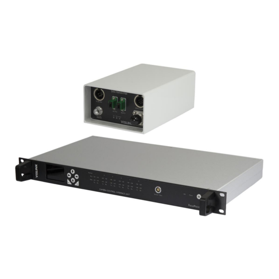
Page 39: Camera Control Data Transmitter - Fcdt-Assy-7Xxx
WARNING: This unit contains a class 1 laser module. Lasers can cause irriversable eye damage. Do not stare directly or indirectly at the laser beam. Figure 4-2 FCDT-ASSY7xxx Connectors and Indicators Overview Issue No: M Page: 31 Ref: FOCL-ASUM-8xxx Copyright © 2017 Vislink plc... -
Page 40: Specifications
The FocalPoint system is capable of connecting one to eight Data Transmitter units to a single Control Interface unit. Each unit must have a separate address allocated. The Data connection is RS485 2-wire only. Issue No: M Page: 32 Ref: FOCL-ASUM-8xxx Copyright © 2017 Vislink plc... - Page 41 The Data Transmitter requires an antenna system suitable to the frequencies in use. A Vislink Flat Plate Directional antenna may be supplied for this purpose. However, other antennas in the appropriate frequency range are acceptable and may be used to provide increased gain if required.
- Page 42 User Manual Focal Point Camera Control Data Transmitter - FCDT-ASSY-7XXX This page is intentionally unused. Issue No: M Page: 34 Ref: FOCL-ASUM-8xxx Copyright © 2017 Vislink plc...
-
Page 43: Data Receiver
OCP/RCP. All of the Data Receivers have a Carrier LED. This will only flash when data is received e.g. when the OCP/RCP joystick is moved. Issue No: M Page: 35 Ref: FOCL-ASUM-8xxx Copyright © 2017 Vislink plc... -
Page 44: Data Receiver
NOTE: Return data is available to the OCP5 if the user data out from the MVL Receiver is connected directly to the OCP5 @ 115200 baud. You can control the camera from a PC with Windows™ OS installed, using the Vislink software IncamProgrammer.exe. User instructions are available from the user guide, which is accessed from the GUI. - Page 45 BNC 75Ω BNC 75Ω BNC 75Ω Connector 3-Pin XLR Socket Signal Hot+ Cold- Connector 5-Pin, 1-Key LEMO Socket Signal +12V Tally Connector 3-Pin Binder Socket Signal Data Issue No: M Page: 37 Ref: FOCL-ASUM-8xxx Copyright © 2017 Vislink plc...
- Page 46 OCP5 @ 115200 baud. NOTE: One-way data or return data is available when using the Sony RCP 750/1500/1530. You can control the camera from a PC with Windows™ OS installed, using the Vislink software IncamProgrammer.exe. User instructions are available from the user guide, which is accessed from the GUI.
- Page 47 The Data connector allows Remote connectivity to various camera manufactures and models by using the correct Data Cable. The FocalPoint Camera Control system offers control to various camera manufactures and models using one-way data with the Vislink OCP5 and one-way or return data using any of the following: ...
- Page 48 The data connector allows remote connectivity to various camera manufactures and models using the correct data cable. The FocalPoint Camera Control system offers control to various camera manufactures and models using one-way data with the Vislink OCP5 and one-way or return data using any of the following: ...
- Page 49 Green Tally Signal TTL TX (TTL CC Hitachi) TTL RX (TTL CC Hitachi) Connector 2-Pin, 1-Key LEMO Socket Signal 9-18V DC Input Connector 2-Pin, 1-Key LEMO Socket Signal Data Out Issue No: M Page: 41 Ref: FOCL-ASUM-8xxx Copyright © 2017 Vislink plc...
- Page 50 L17xx with FocalPoint Camera Control Configuration Options NOTE: FocalPoint ‘Scan Mode’ is not available with the L17xx Camera Control. Refer to the L1700 manual for full product information and safety awareness. Issue No: M Page: 42 Ref: FOCL-ASUM-8xxx Copyright © 2017 Vislink plc...
-
Page 51: Operators Control Panel (Ocp5) Ocp5-Assy-7Xxx
Operators Control Panel (OCP5) OCP5-ASSY-7XXX Figure 6-1 Operators Control Panel Overview The Vislink Operator’s Control Panel (OCP) is designed for use in conjunction with the FocalPoint Camera Control system and Data Receiver. The unit is designed to fit a standard OCP/RCP slot. -
Page 52: Ocp5 Control Functions
Use the Data in/out connector to handle the Data input from the camera to the OCP5. NOTE: When used for return data to the Vislink OCP5, set the User Data port on the microwave video link (transmitter and the receiver) to a baud rate of 115,200. - Page 53 TXD- TXD+ This port is used for Return data from the User Data port of the MVL Receiver (if used). Connector XLR 5-Pin Signal TXD- TXD+ RXD- RXD+ Issue No: M Page: 45 Ref: FOCL-ASUM-8xxx Copyright © 2017 Vislink plc...
-
Page 54: Dc Input
Ethernet port for remote control and monitoring. USB port for unit software upgrade. Connector 8-pin LEMO Connector EGG.1B.308.CLN Signal Function Ethernet 0V GND USB_+ USB_- +5V out Issue No: M Page: 46 Ref: FOCL-ASUM-8xxx Copyright © 2017 Vislink plc... -
Page 55: Camera Types
Grass Valley LDX 80, LDX 86, LDX C80 DK-H100 Hitachi DK-H100 HD-1200E Hitachi SK-HD1200E, SK-900E, SK-HD1000 AJ-HPX2000 Panasonic AJ-HPX2000E, AJ-HPX3100G JVC D29 JVC KY-D29 GW HDMC Vislink ‘HDMC’ Table 6-2 OCP5-ASSY-7XXX Camera Types Issue No: M Page: 47 Ref: FOCL-ASUM-8xxx Copyright © 2017 Vislink plc... -
Page 56: Ocp5 Menu Structure
User Manual Focal Point Operators Control Panel (OCP5) OCP5-ASSY-7XXX Figure 6-3 OCP5 Menu Structure Issue No: M Page: 48 Ref: FOCL-ASUM-8xxx Copyright © 2017 Vislink plc... - Page 57 Next or Previous To access these screens from the main operator screen press Menu and Next as required to reach the required sub-menu. Figure 6-5 Example Setup Screens Issue No: M Page: 49 Ref: FOCL-ASUM-8xxx Copyright © 2017 Vislink plc...
- Page 58 User Manual Focal Point Operators Control Panel (OCP5) OCP5-ASSY-7XXX This page is intentionally unused. Issue No: M Page: 50 Ref: FOCL-ASUM-8xxx Copyright © 2017 Vislink plc...
-
Page 59: Useful Part Numbers
User Manual Focal Point Useful Part Numbers Figure 7-1 Useful Part Numbers Issue No: M Page: 51 Ref: FOCL-ASUM-8xxx Copyright © 2017 Vislink plc... - Page 60 RCP1530 OCP/RCU Units OCP400 RU1500 OCP300 INCAM-S Sony HDC 2500 INCAM-G Grass Valley LDX 80 UHF Data Receivers DR07 L1700 ClipOn4 CCCU Table 7-1 Useful Unit Part Numbers Issue No: M Page: 52 Ref: FOCL-ASUM-8xxx Copyright © 2017 Vislink plc...
- Page 61 Useful Cable Part Numbers Figure 7-2 Wireless Camera Receivers Wireless Camera Receiver Return Data Cable Part No. CARK-ASSY-2025 L2174 CARK-ASSY-2024 MTV-HD3 CARK-ASSY-2027 MVL-HD3 Table 7-3 Wireless Camera Receivers ID Table Issue No: M Page: 53 Ref: FOCL-ASUM-8xxx Copyright © 2017 Vislink plc...
- Page 62 User Manual Focal Point Useful Part Numbers This page is intentionally unused. Issue No: M Page: 54 Ref: FOCL-ASUM-8xxx Copyright © 2017 Vislink plc...
- Page 63 User Manual Focal Point Camera Control Data Receiver Cables Vislink cable part number: CCCU-ASSY-2035 Data Receiver Camera Connector 5-Pin LEMO Plug 9-way, D-type Socket FGG.0B.305.CLAD52Z Vislink cable part number: DR07-ASSY-2020 Data Receiver Camera Connector 5-Pin LEMO Plug FGG.0B.305.CLAD52Z 9-way, D-type Socket 2-pin LEMO Plug FGG.0B.302.CLAD52...
- Page 64 User Manual Focal Point Camera Control Data Receiver Cables Vislink cable part number: DR07-ASSY-2003. NOTE: Optional 3-meter cable part number: DR07-ASSY-2014. Data Receiver Camera Connector 5-Pin LEMO Plug FGG.0B.305.CLAD52Z 8-Pin Hirose Plug HIROSE, MXR–8P–8P 6 2-pin LEMO Plug FGG.0B.302.CLAD52 Connector...
- Page 65 User Manual Focal Point Camera Control Data Receiver Cables Vislink cable part number: DR07-ASSY-2012. Data Receiver Camera Connector 6-Pin LEMO Plug FGG.0B.306.CLAD52Z 4-Pin Hirose Plug 2-pin LEMO Plug HR107P4P FGG.0B.302.CLAD52 Connector 6-Pin 2-Pin Vislink cable part number: CCCU-ASSY-2034 Data Receiver...
- Page 66 User Manual Focal Point Camera Control Data Receiver Cables Vislink cable part number: CCCU-ASSY-2032 Data Receiver Camera Connector 5-Pin LEMO Plug 10-Pin Hirose Plug FGG.0B.305.CLAD52Z HIROSE, HR10A-10P-10P 6-Pin LEMO Plug 4-Pin Hirose Plug FGG.0B.306.CLAD52 HR107P4P Connector Connector 10-Pin 10-Pin 5-Pin...
-
Page 67: Camera Control Interface To Ocp/Rcp Cables
User Manual Focal Point Camera Control Interface to OCP/RCP Cables Vislink cable part number: CARK-ASSY-2022 Camera Control Interface OCP/RCP Connector 8-Pin Hirose Plug 15-Way D-Type Plug HIROSE, MXR–8P–8P 6 12 – 15 Link 15 – 12 Link Vislink cable part number: RHD9-ASSY-2018... - Page 68 User Manual Focal Point Camera Control Interface to OCP/RCP Cables Vislink cable part number: CARK-ASSY-2029 Camera Control Interface OCP/RCP Connector 8-Pin TAJIMI Connector 15-Way D-Type Plug PRC90-199-P9-P8F Vislink cable part number: CARK-ASSY-2028 Camera Control Interface OCP/RCP Connector 10--Pin Hirose Plug 15-Way D-Type Plug HIROSE, HR10–10P–10S(73)
- Page 69 User Manual Focal Point Camera Control Interface to OCP/RCP Cables Vislink cable part number: RHD9-ASSY-2014 Camera Control Interface OCP/RCP Connector 15-Way D-Type Plug 9-Way D-Type Socket 3-Pin XLR Plug Connector Connector 9-Way 9-Way 9-Way 15-Way 9-Way 3-Pin 9-Way 3-Pin 9-Way...
- Page 70 User Manual Focal Point Camera Control Interface to OCP/RCP Cables Vislink cable part number: CARK-ASSY-2032 Camera Control Interface OCP/RCP Connector 9-Way D-Type Plug 15-Way D-Type Plug 4-Pin XLR Socket Connector Connector 4-Pin XLR 9-Way 9-Way 9-Way 9-Way 15-Way 4-Pin XLR...
Need help?
Do you have a question about the FCDT-ASSY-7002 and is the answer not in the manual?
Questions and answers