
Related Manuals for ISG Allegro LW-AL-CMV2000C-USB3 COLOR

Summary of Contents for ISG Allegro LW-AL-CMV2000C-USB3 COLOR
- Page 1 Technical Manual Allegro USB3 Vision™ Cameras Version 2.0.2 Last Revision 6/20/2018 1387 Fairport Road, Suite 890 | Fairport, NY 14450 | P: 585-388-5220 | F: 585-388-5223 | isgcameras.com...
-
Page 2: Table Of Contents
Table of Contents Introduction ..............................5 About This Guide ............................5 Support ................................5 FCC Compliance ............................6 Hardware Warranty ............................6 WEEE ................................6 Trademarks ..............................6 Allegro USB3 Specifications ..........................7 General Specifications ..........................7 Handling Precautions and Camera Care ....................10 Case Temperature and Heat Dissipation .................... - Page 3 Rolling Shutter with Global Reset ......................18 Allegro USB Software and Control ....................... 19 Using the Medley SDK ..........................19 Custom Applications Built Using the ISG Legacy API ................19 Allegro USB3 Operation using GenICam ....................20 Using GenICam Applications ........................20 GenICam Acquisition Control ........................
- Page 4 Camera Trigger Details ..........................44 Camera Strobe Details ..........................45 Page 4 of 45 isgcameras.com...
-
Page 5: Introduction
Introduction Allegro smart cameras are the Intelligent Solution for your needs. Allegro cameras feature compact form factors, high resolution and high performance, along with unmatched programmability and flexibility for vision system designers. We put more intelligence in the camera with large FPGAs, huge image buffers and other features to improve performance and simplify integration. -
Page 6: Fcc Compliance
FCC Compliance This device complies with Part 15 of the FCC rules. Its operation is subject to the following two conditions: 1. This device may not cause harmful interference 2. This device must accept any interference received, including interference that may cause undesirable operation. -
Page 7: Allegro Usb3 Specifications
Allegro USB3 Specifications Building on the success of the original LightWise 1394 camera series, the Allegro camera offers many new features, including enhanced opto-isolated GPIO, an on-camera frame buffer, non-volatile flash memory for data storage, new trigger modes and improved imaging performance. General Specifications Camera Name Technology... - Page 8 LW-AL-IMX253M-USB3 MONO Sony CMOS IMX253 12.3 MP 4096 x 3.45 Color 3000 µm LW-AL-FK160K-USB3-COLOR Omnivision CMOS OV6946 160k 400 x 400 1.75 µm Color Page 8 of 45 isgcameras.com...
- Page 9 Mass Power Consumption 5V via USB3.0 interface, maximum <4.5W Machine Vision Standard IIDC v 1.32, USB3 Vision v1 Camera Control Via ISG SDK, CSRs, or third party software Camera Updates In-field firmware updates Lens Mount C-mount Temperature Operating: 0 to 5o C; Storage -30 to 70 C Humidity Operating: 20 to 80% (no condensation);...
-
Page 10: Handling Precautions And Camera Care
Handling Precautions and Camera Care Opening the camera housing will cause damage and will void the hardware warranty detailed in the beginning of this document. Since the Allegro Camera is a precisely manufactured device it must be handled with care. Some tips for device care are below: 1. -
Page 11: Allegro Usb3 Installation
4. Tripod adapter (optional) (see Mounting with the Case or Optional Tripod Mount) 5. Interface card ISG sells a number of the additional parts required for installation. To purchase, please visit the ISG Web Site. www.isgcameras.com Page 11 of 45... -
Page 12: Do You Have The Required Software
4. Documentation Installing your Software Overview In order to operate the ISG USB3 camera, please visit the ISG website (http://www.isgcameras.com) for the software downloads and installation instructions. For more information see Allegro USB Software and Control in this document. Installing Your Camera 1. -
Page 13: Camera Firmware
Camera Firmware Firmware is programming that is inserted into the programmable memory (programmable ROM) of ISG cameras. Firmware is created and tested like software. When ready, it can be distributed like other software and installed in the programmable memory by the user. -
Page 14: Allegro Usb3 Attributes
Allegro USB3 Attributes Pixel Formats The pixel formats describe the encoding scheme of the pixels in the camera output images. Pixel formats describe each pixel in terms of color encoding, bit depth and formatting within the data stream. Pixel formats conform to the GenICam Pixel Format Naming Convention (PFNC) v2.0. The full PFNC can be found on the EMVA.org website and contains more details than provided below. -
Page 15: Image Format Control
Image Format Control Name Display Name Description Value Width Width Width of the image provided Sensor Dependent by the device (in pixels) Height Height Sensor Dependent Height of the image provided by the device (in pixels Offset X X Offset Horizontal offset from the origin to the region of interest (in pixels) -
Page 16: Shutter Types
Shutter Types Global Shutter For each frame in cameras with a global shutter sensor the start and stop time for exposure is the same. The length of time for exposure is also the same. For cameras with a global shutter sensor, for each frame all of the lines start and stop exposure at the same time. The exposure time for each line is the same. -
Page 17: Rolling Shutter
Rolling Shutter For each frame in cameras with a rolling shutter sensor the exposure for each line begins at an offset equal the readout time for each line. While the exposure time for each line is the same, the start and stop times are staggered. Each line’s data readout begins immediately following the exposure. -
Page 18: Rolling Shutter With Global Reset
Rolling Shutter with Global Reset For each frame in cameras with a rolling shutter with global reset, the lines have the exposure start time while the stop time for exposure is delayed by the offset of the previous line’s readout. For each line the exposure time gradually lengthens and data readout begins immediately following the line’s exposure. -
Page 19: Allegro Usb Software And Control
Custom Applications Built Using the ISG Legacy API The ISG API that allows customers to create custom applications to control ISG Imaging Products. Included in downloads that are available on the ISG web site are a number of source code examples to help programmers get started. -
Page 20: Allegro Usb3 Operation Using Genicam
Allegro USB3 Operation using GenICam Using GenICam Applications USB3 Vision is a communication interface for vision applications based on the USB 3.0 technology. All cameras supporting USB3 Vision interact the same way with software also supporting USB3 Vision. The standard defines required elements for camera identification, control, and output. It uses GenICam, a programming interface for camera attribute control. - Page 21 Specifies the delay in microseconds (us) to apply after the trigger reception before activating it. TiggerInterval Tigger Interval ISG custom register that specifies the time between the start of Burst frames in useconds TriggerSoftware Generate Software Trigger Generates an internal trigger. TriggerSource must be set to Software.
-
Page 22: Transfer Mode Summary
Transfer Mode Summary For the various transfer modes in the table below, the following are always set: AcquisitionMode - Continuous TriggerActivation - RisingEdge, FallingEdge TriggerSource - Software (use TriggerSoftware to activate), Line0 TriggerDelay - D elay value (usec) TriggerInterval - Interval value for Burst Frames mode only (usec) Transfer Mode TriggerMode TriggerSelector... -
Page 23: Trigger And Strobe Control
TriggerDelay – Specifies the delay in microseconds to apply after the trigger reception before activating it. TriggerInterval – An ISG Custom register that specifies the time between the start of frames in useconds. The user should set this to be greater than the higher of either integration time or readout time. -
Page 24: Standard External Trigger
Standard External Trigger In this mode, camera frames are generated using an external signal. When the input signals selected edge is detected, the image sensor begins integration followed by image readout. Figure 7.1: Standard External Trigger Mode GenICam—Acquisition Control Acquisition Mode Continuous Trigger Selector Frame Start... -
Page 25: Bulb Shutter Trigger
Bulb Shutter Trigger Also known as Bulb Shutter mode, the camera starts integration with the leading edge of the input trigger. Integration time terminates on the trailing edge of the input trigger. Figure 7.2: Bulb Shutter Trigger GenICam—Acquisition Control Acquisition Mode Continuous Trigger Selector Frame Start... -
Page 26: Burst Mode Trigger (Edge Detect)
Burst Mode Trigger (Edge Detect) This trigger mode allows x number of frames to be generated with one trigger input (hardware or software). The frames are generated when the selected trigger edge is detected. The trigger interval value will determine frame rate. -
Page 27: Burst Mode Trigger (Level Detect)
Burst Mode Trigger (Level Detect) In this trigger mode sensor triggers will be generated as long as the input trigger is active. NOTE: Depending on the sensor, the maximum frame rate in triggered mode may not be the same as in continuous mode. Frames are generated while trigger is active Sensor Exposure... -
Page 28: External Trigger Timing
External Trigger Timing The time from the external trigger firing to the start of shutter is shown below: 1. Trigger Pulse 2. Propagation Delay 3. Exposure Time 4. Sensor Readout 5. Data Transfer Figure 7.4: External trigger timing characteristics Asynchronous Software Triggering Shutter integration can be initiated by a software trigger by setting the Trigger Source to Software in the GenICam features. -
Page 29: Programmable Strobe Output
Programmable Strobe Output The camera has two independent programmable strobe outputs. The strobe control input can be driven by the sensor (sensor integration active) or the hardware trigger input. This allows for very flexible strobe control. By default, the strobe_1 output is a positive going pulse during sensor integration and the strobe_2 output is an inverted version of strobe_1. -
Page 30: Genicam Additional Features
GenICam Additional Features Features that control, monitor and query camera operation are included in the XML device description file on the camera. Since not all operations can be controlled using the XML file those not included are controlled via CSRs. Except where noted, these features conform to the GenICam Standard Features Naming Convention (SFNC) v2.3. - Page 31 used to create the device`s GenICam DeviceManifsetXMLMajorVersion XML Major Version Indicates the major version number of the GenICam XML file of the selected manifest entry DeviceManifsetXMLMinorVersion XML Minor Version Indicates the minor version number of the GenICam XML file of the selected manifest entry DeviceManifsetXMLSubMinorVersion XML Subminor Version...
-
Page 32: Digital Io Control
Digital IO Control Name Display Name Description Value LineSelector Strobe Selector Selects the physical line (or pin) of the Strobe1 external device connector to configure Strobe2 LineMode Line Mode Controls if the physical Line is used to Output Input or Output a signal LineInverter Invert Strobe Output Controls the inversion of the signal of the... -
Page 33: Analog Control
Analog Control Name Display Name Description Value GainSelector Gain Selector Selects which Gain is DigitalAll controlled by the various Gain features Gain Gain Controls the selected gain as an absolute physical value. This is an amplification factor applied to the video signal BlackLevelSelector Black Level Selector... -
Page 34: Transport Layer Control
Transport Layer Control Name Display Name Description Value PayLoadSize Pay Load Size Provides the number of bytes transferred for each image or chunk on the stream channel. This includes any end-of-line, end-of-frame statistics or other stamp data. This is the total size of data payload for a data block CurrentSpeed Current Speed... -
Page 35: User Sets
User Sets The camera can save and restore settings and imaging parameters via on- board user configuration sets, also known as User Sets. This is useful for saving default power-up settings, such as gain, shutter, video format and frame rate, and others that are different from the factory defaults. UserSet0 stores the factory default settings that can always be restored. -
Page 36: Genicam User Set Control
In most instances the CMV12000 will need additional power. If you experience the insufficient power issue, there are a few options to choose from to sufficiently power the camera. For further details and information on the solutions listed below, please visit the accessories section of ISG’s website (http://www.isgcameras.com/). -
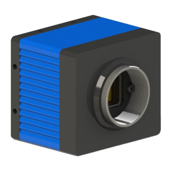
Page 37: Allegro Usb3 Physical Description
Allegro USB3 Physical Description 1. Lens holder C Mount Lens ready. (CS Mount available by special order. 2. Glass/IR filter system Dust protective glass on monochrome cameras, IR Cut filter on color models. Removable and mounted behind Lens Holder Page 37 of 45 isgcameras.com... - Page 38 3. M3x.5 THD x 5 DP mounting holes Eight locations on camera case for multiple mounting options. 4. General purpose I/O connector The 12 – pin Trigger/Strobe connector. See Trigger and Strobe Control 5. Status LED This light indicates the current state of the camera operation. See Status Indicator LED 6.
-
Page 39: Allegro Usb3 Dimensions
Allegro USB3 Dimensions LW-AL-CMV-4000/2000 shown below Drawings and 3D models for all model numbers available on the ISG Web Site FRONT PANEL SIDES BOTTOM REAR PANEL Page 39 of 45 isgcameras.com... -
Page 40: Mounting With The Case Or Optional Tripod Mount
Mounting with the Case or Optional Tripod Mount The case provides the following mounting holes: 1. Eight (8) M3 x .5 mounting holes on the top bottom and sides of the case. 2. The two M3 x .5 mounting holes on the front bottom of the case can be used to attach the optional tripod mount. -
Page 41: Infrared Cutoff Filters
Infrared Cutoff Filters ISG color camera models are shipped with an infrared (IR) cut- off filter. This filter can reduce sensitivity in the near infrared spectrum and help prevent smearing. The properties of this filter are illustrated in the transmission curve below. -
Page 42: Usb 3.0 Connector
USB 3.0 Connector The camera is equipped with a USB 3.0 Micro-B connector that is used for data transmission, camera control and power. For more detailed information, consult the USB 3.0 specification available from http://www.usb.org/developers/docs/. Figure 4.5: USB 3.0 Micro B Connector Signal Name Description VBUS... -
Page 43: Interface Cables
Interface Cables Because there is not a standard maximum cable length specified in the USB 3.0 standard you may need to purchase a recommended cable. To do so please visit the ISG web site. www.isgcameras.com. Interface Card In order to achieve optimum benefits of the USB 3.0 the camera must connect to a USB PCIe 2.0 card. - Page 44 Camera Trigger Details The external interface consists of one isolated programmable Trigger Input and two isolated programmable Strobe outputs. 1. Trigger input: The camera receives one optically isolated trigger input. The interface consists of 2 wires a. Trigger In (signal) b.
- Page 45 Camera Strobe Details Strobe1-2 outputs: The camera provides two optically isolated Strobe outputs (NPN transistor). The output modes (level high or level low and pulse duration) are programmable. The following diagram shows the interface circuit for each of the Strobe outputs. Note: the amount of current flow, IC, is the function of User-resistor- Load and User-VCC.
Need help?
Do you have a question about the Allegro LW-AL-CMV2000C-USB3 COLOR and is the answer not in the manual?
Questions and answers