Advertisement
Table of Contents
- 1 Table of Contents
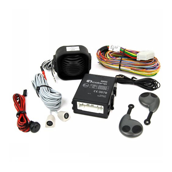
- 2 Kit Contents
- 3 System's Configuration
- 4 How to Prepare the Pin Code Card
- 5 Installation Procedure
- 6 ACTIVE FUNCTIONALITIES (Descriptions)
- 7 PROGRAMMABLE FUNCTIONS (See the "Functions Programming Tables" Manual)
- 8 (See 'PAGE 2' of the "Functions Programming Tables" Manual)
- 9 NEW REMOTE CONTROLS and / or DRIVER CARDS (Optionals) SELF LEARNING PROCEDURE
- 10 Functional Test
- 11 Self Learning Procedure Required to Replace the Main Unit or the Wireless Siren Replacement
- 12 Documents Handover
- 13 System Technical Specifications
- Download this manual
Advertisement
Table of Contents

Related Manuals for Cobra 4693


Summary of Contents for Cobra 4693
- Page 1 4693-4698 INSTALLATION MANUAL...
-
Page 2: Table Of Contents
(see ‘PAGE 2’ of the “Functions programming tables” manual) ................18 9. FUNCTIONAL TEST ..............................18 10. SELF LEARNING PROCEDURE REQUIRED TO REPLACE THE MAIN UNIT OR THE WIRELESS SIREN REPLACEMENT ................................18 11. DOCUMENTS HANDOVER ............................19 12. SYSTEM TECHNICAL SPECIFICATIONS ........................19 13. UK MARKET ................................19 INSTALLATION MANUAL 4693-4698... -
Page 3: Kit Contents
This manual contains all information required to fi t the system on 12 V battery vehicles with the negative pole connected to the vehicle body. HOW TO ACCESS TO THE VEHICLE SPECIFIC TECHNICAL DOCUMENTS. Access to the web site www.cobra-es.com > Professional area and register yourself to be allowed to download the technical documentation. HOW TO DEFINE THE INSTALLATION SOLUTION. -
Page 4: How To Prepare The Pin Code Card
4. - HOW TO PREPARE THE PIN CODE CARD. Remove the separate PIN Code label from the back of the system main unit and place onto the supplied PIN Code Card. CODE 1122 4C4415A2A S/N 0003 050524 PERSONAL IDENTIFICATION CODE CODE 1122 INSTALLATION MANUAL 4693-4698... -
Page 5: Installation Procedure
The RF antennas positioning (for both the main unit and the siren) is crucial for a proper system’s performance. They must not be cut, wrapped, connected to any other cables or to the vehicle body and they must be kept separate from the main wiring harness and as far as possible from metallic parts. INSTALLATION MANUAL 4693-4698... - Page 6 Pay attention when joining two or more wires. Avoid to make “quick connections” that do not ensure a good quality. Also make sure that the wires of the Cobra 469X are routed so that they follow the original wiring of the vehicle to which they should be joined with the raps.
- Page 7 0,25 m. Vedi schema " " THE FUSES ARE NOT SUPPLIED IN THE KIT See " " diagram YELLOW-BLUE BLACK J-15 COBRA BUS J-14 GREEN max 20 A (1 s) GREEN 6 A cont. YELLOW...
- Page 8 COLLEGAMENTI SIRENA NO WIRELESS (5362) PULSANTE COFANO NO WIRELESS SIREN CONNECTIONS (5362) BONNET PUSH-BUTTON See the car fitting instructions J-21 BLACK BLUE Ø YELLOW-BLUE YELLOW-BLUE Ø Ø BLACK BLACK PANNELLINO LED LED PANEL COLLEGAMENTI SIRENA WIRELESS (5365) WIRELESS SIREN CONNECTIONS (5365) See the car fitting instructions BLUE...
- Page 9 Filo BIANCO WHITE wire J17 BLACK (TX) BLACK WHITE (RX) U.S. sensors, LED panel Install the jumper wire (see the catalogue) and antenna connections. between the U.S. TX and RX, if you don't use the volumetric sensor. Filo BIANCO WHITE wire J17 Filo BIANCO WHITE wire J17 30 86 85 1N4004...
- Page 10 CHIUSURE CENTRALIZZATE CENTRAL DOOR LOCKING ORANGE ADDITIONAL MOTOR BLUE ORANGE VIOLET VIOLET 7,5 A BROWN ORANGE-WHITE 7,5 A ORANGE-WHITE 7,5 A VIOLET-WHITE 7,5 A VIOLET-WHITE YELLOW-BLACK YELLOW-BLACK NOT USED (TO ISOLATE) GREY-BLACK GREY-BLACK VEHICLES WITH NEGATIVE CDL PULSE VEHICLES WITHOUT ACTUATOR IN THE DRIVER’S SIDE DOOR ORANGE 7,5 A VIOLET...
- Page 11 The input is 7 s delayed after the system arming. J-23 Negative input for additional modules: to be used as a triggering input for the connection of compatible Cobra modules. J-24 (see central door locking diagrams).
-
Page 12: Active Functionalities (Descriptions)
The LED main scope is to show the system arming and disarming conditions. When the system is armed the LED gets ON and remains illuminated until the 25 s arming period has elapsed. After that it starts blinking. It goes OFF as soon as the system is disarmed. INSTALLATION MANUAL 4693-4698... - Page 13 9 fl ashes Not used. 10 fl ashes Not used. 11 fl ashes Immobilizer 1 module connected to the Cobra Bus. 12 fl ashes Immobilizer 2 module connected to the Cobra Bus. 13 fl ashes Not used. 14 fl ashes Not used.
-
Page 14: Programmable Functions (See The "Functions Programming Tables" Manual)
G. Turn the ignition key OFF and disconnect the BLU wires of the main unit and of the siren from GND (if grounded through the additional pushbutton simply open the bonnet). Check the system functionality arming the system and triggering the alarm to check the proper sounding of the siren. INSTALLATION MANUAL 4693-4698... -
Page 15: Documents Handover
- Central dimensions 91x69x35 mm - Siren dimensions 113x79x45 mm Trasmitter battery / Cobra Driver Card Lithium Battery 3 V CR2032 13. - FOR MARKET ONLY Category 1,2 or 2-1 systems permanently installed as aftermarket equipment by import or distribution centres, vehicle dealers, or by Independent Installers, shall be installed by companies and technicians who are trained, qualifi... - Page 16 Cobra Automotive Technologies via Astico 41 - 21100 VARESE - ITALY www.cobra-at.com 06DE3796A - 03/13...
Need help?
Do you have a question about the 4693 and is the answer not in the manual?
Questions and answers