Table of Contents
Advertisement
Quick Links
Advertisement
Table of Contents

Related Manuals for Vericom VC4000


Summary of Contents for Vericom VC4000
-
Page 2: Table Of Contents
Modes ................... 10 Tools ..................... 13 3. ACCIDENT RECONSTRUCTION USE ........14 Initial Setup ................... 14 Get VC4000 Ready ..............15 Measuring Drag Factor ..............18 Testing Brake Performance ............19 Measuring Coefficient of Friction ..........20 Light Impact Testing ..............23 Avoiding False Triggering ............. - Page 3 Measuring Slope ................60 7. VC4000 SETUP ................61 Setup Flowchart ................63 G Threshold .................. 65 Vehicle ID ..................65 Set Defaults .................. 66 Date/Time ..................67 Pitch/Roll Factors ................. 67 User Type ..................69 English/Metric ................71 RS232 Port ................... 72 Brake MPH ...................
- Page 4 USB Port ..................95 11. UPDATING FIRMWARE ............96 12. CHARGING THE BATTERY ............. 98 13. CUSTOMER SERVICE .............. 99 Warranty ..................99 Repairs ..................99 Options, Upgrades and Accessories .......... 100 14. TROUBLESHOOTING ............. 101 15. SPECIFICATIONS ..............103...
-
Page 5: Introduction
1. INTRODUCTION ecades of refinement make the VC4000 the best yet. The VC4000 has been designed for ease of use and simplicity of operation for quick and easy results, yet has advanced features for doing much more. The unit is preprogrammed with standard defaults so that it is ready to operate immediately. -
Page 6: Features
If you can’t find what you are looking for, go to our web site’s support pages for more detailed information. This manual covers the VC4000 Brake Meter and the VC4000PC. When you see “(PC)” means it applies to the VC4000PC model only. -
Page 7: What It Comes With
What it comes with Check to see that the following items are supplied with your VC4000: VC4000 with single cup mounting assembly Power cord (to cigarette lighter) AC wall adapter USB interface cable (PC) VC4000 manual Profile CD (PC) Carrying case Optional Accessories: ... -
Page 8: Operation Basics
VC4000. Mounting The VC4000 does not have to be level to get accurate results. It uses a 3 axis accelerometer and calculates the vector sum of all 3 axes to calculate G force, speed and distance. G “Summation 3D (XYZ)”... - Page 9 Figure 2: Single mount on side window The VC4000 uses a single mounting arm and a pump up vacuum cup to attach to the windshield or side window. The VC4000 and the suction cup each have a plate with a ball that the arm attaches to.
- Page 10 Figure 4: Dual cups mount If you do not wish to use the batteries, plug the power cord into the back of the VC4000 and into the vehicle's cigarette lighter. Plug external accessories such as VSI or GPS into VC4000.
-
Page 11: Powering Up
Sometimes when a sensor is plugged in when the VC4000 power is on the unit will shut off due to the inrush current when the sensor first powers on. This is why we recommend plugging in all accessories with the power off. -
Page 12: Display And Keypad
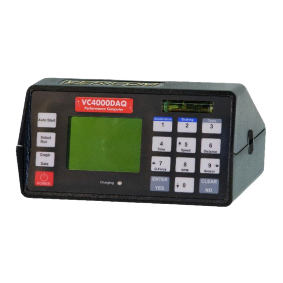
Display and Keypad Display The VC4000 uses a graphic and text display. It has large letters so it is easy to see from a distance, such as on a windshield when viewing from the drivers’ seat. The display and keypad are lighted for viewing in low light. - Page 13 GPS or VSI graphs. Sensor Enter the numeric 0 or scroll down. Enter information, select a menu item or respond YES ENTER to a prompt. Clear memory, clear information, go back to previous CLEAR screen or respond NO to a prompt. VC4000 Manual...
-
Page 14: Menus
See page 79 in setup for more details on zeroing. The VC4000 will zero adjust the accelerometers to the current angle the unit is facing. Press the “Auto Start”... - Page 15 Basic steps for brake testing: 1. Connect GPS or VSI if you are using them. (PC) 2. Mount the VC4000. 3. Position the vehicle on the same incline as the test is being performed. 4. Press the Braking key. Unit will zero adjust itself.
- Page 16 Acceleration key. The VC4000 will use the zero reference from the previous test or if zeroing was turned off it will use the zero reference established at the factory.
-
Page 17: Tools
Tools Tools The VC4000 has several tools available. Press the key to bring up a list of available tools. Below is a list of the tools and a short description of each tool. Monitor Crash Mode Cal. Check Setup Delete Run... -
Page 18: Accident Reconstruction Use
5. Press CLEAR / NO to get back to the READY screen. Or use Profile to change the setup in the VC4000 from your PC: 1. Start the Profile program 2. Connect the VC4000 to your computer 3. Turn on the VC4000 4. -
Page 19: Get Vc4000 Ready
Please buckle up and drive safely. Mounting The VC4000 does not have to be level to get accurate results. It uses a 3 axis accelerometer and calculates the vector sum of all 3 axes to calculate G force, speed and distance. G “Summation 3D (XYZ)”... - Page 20 Either use X or X+Y summation if mounting flat and level. Use the bubble levels on the front and left side of the VC4000 to level it, if your vehicle is reasonably flat and level. Within 3 degrees of level is sufficient to get accurate data.
- Page 21 VC4000 will display -0.900 Ave G Attaching accessories It may be easier to plug in cables before mounting the VC4000. If you do not wish to use the batteries on the VC4000 plug the provided power cord into back of VC4000 and into vehicle's accessory jack if one is available.
-
Page 22: Measuring Drag Factor
2. To power on, press the key and hold for 1 second until the unit beeps. Bra king 3. From the “READY” screen press the key with the vehicle at a complete stop. The VC4000 will zero adjust the VC4000 Manual... -
Page 23: Testing Brake Performance
CLEAR / NO key and the VC4000 will retain the calibration for that grade. Press the “Braking” key and repeat step #4. Testing Brake Performance When testing the performance of a vehicles braking system, perform the tests on a flat and level surface. -
Page 24: Measuring Coefficient Of Friction
Bra king 3. From the “READY” screen press the key with the vehicle at a complete stop. The VC4000 will zero adjust the accelerometers, show the available record time in seconds, display the run number being saved, and then display:... - Page 25 Bra king 3. From the “READY” screen press the key with the vehicle at a complete stop. The VC4000 will zero adjust the accelerometers, show the available record time in seconds, display the run number being saved, and then display:...
- Page 26 While reviewing the data after a braking test if the braking key is pressed the VC4000 will start a new braking test using the zero reference established the last time the Braking key was pressed from the “READY”...
-
Page 27: Light Impact Testing
Only the above changes are made during the crash mode. When the test is finished Setup is restored to how it was previously. Up to 10 extra sensors can be turned on and recorded using GPS Speed and VSI sensors. The VC4000PC will record at least one VC4000 Manual... - Page 28 AUTO START READY 4. Accelerate the car to the desired initial speed. After reaching that speed, trigger the VC4000 using the external trigger or it will activate when it impacts an object and generates 4xG-Threshold or more. Using Monitor 1.
-
Page 29: Avoiding False Triggering
Bra king 3. From the “READY” screen press the key with the vehicle at a complete stop. The VC4000 will zero adjust the accelerometers, show the available record time in seconds, display the run number being saved, and then display:... -
Page 30: Measuring Slope
See Acceleration testing on the next page. Measuring Slope The Grade, or Slope, of the road can be very accurately measured using the VC4000. Use the built in Measure Slope tool to measure the slope in Percent Grade and in Degrees. Measure the slope 1. -
Page 31: Acceleration Testing
Acceleration Testing The VC4000 can be used to measure to a preset Time, Speed or Distance. This is useful for: 1. Measuring time and speed from a stop sign to a preset distance at an accident scene in an intersection. - Page 32 7. For a custom test, if you wish to do another test on the same slope (in the same direction) do not press the CLEAR / NO key and the VC4000 will retain the calibration for that grade and use the same custom distance. Press the Acceleration key, select Repeat Last Run and repeat step #5.
-
Page 33: Accel/Brake Run
1800 meters Maximum acceleration Accel/Brake Run The VC4000 can be used to measure an acceleration test then a brake test from one run. This is useful for measuring the acceleration to a point then getting a drag factor without having to come to a stop and re-zero. - Page 34 6. Then it will display 'Auto-Start-Ready' and the current G reading. 7. Accelerate the vehicle until the VC4000 beeps indicating it has reached the preset. 8. Now apply the brakes to perform a brake test. The unit will beep 5 short times when activated and beep again when at a complete stop.
-
Page 35: Transit Use
5. Press CLEAR / NO to get back to the READY screen. Or use Profile to change the setup in the VC4000 from your PC: 1. Start the Profile program 2. Connect the VC4000 to your computer 3. Turn on the VC4000 4. -
Page 36: Get Vc4000 Ready
Please buckle up and drive safely. Mounting The VC4000 does not have to be level to get accurate results. It uses a 3 axis accelerometer and calculates the vector sum of all 3 axis to calculate G force, speed and distance. G “Summation 3D (XYZ)”... - Page 37 Figure 11: Dual cups mount Attaching accessories It may be easier to plug in cables before mounting the VC4000. If you do not wish to use the batteries on the VC4000 plug provided power cord into back of VC4000 and into vehicle's accessory jack if one is available.
- Page 38 6. Press CLEAR / NO twice to get back to the READY screen Or use Profile to change the setup in the VC4000 from your PC: 1. Start the Profile program 2. Connect the VC4000 to your computer 3. Turn on the VC4000 4.
-
Page 39: Testing Brake Performance
Bra king 3. From the “READY” screen press the key with the vehicle at a complete stop. The VC4000 will zero adjust the accelerometers and applicable sensors, show the available record time in seconds, display the run number being saved,... - Page 40 G-Force. While reviewing the data after a braking test if the braking key is pressed the VC4000 will start a new braking test using the zero reference established the last time the Braking key was pressed from the “READY”...
-
Page 41: Engineering Use
Please buckle up and drive safely. Mounting The VC4000 does not have to be level to get accurate results. It uses a 3 axis accelerometer and calculates the vector sum of all 3 axis to calculate G force, speed and distance. G “Summation 3D (XYZ)”... - Page 42 Figure 14: Dual cups mount Attaching accessories It may be easier to plug in cables before mounting the VC4000. If you do not wish to use the batteries on the VC4000 plug provided power cord into back of VC4000 and into vehicle's accessory jack if one is available.
- Page 43 Figure 15: VC4000 back panel (PC) Turn on external sensors if using them Each GPS or VSI sensor must be turned on for the VC4000 to record data from it. 1. Press the Tools key 2. Scroll to Setup and press ENTER / YES Sensors…...
-
Page 44: Testing Brake Performance
Bra king 3. From the “READY” screen press the key with the vehicle at a complete stop. The VC4000 will zero adjust the accelerometers and applicable sensors, show the available record time in seconds, display the run number being saved,... - Page 45 Avg. Gx: Average longitudinal G force from when the VC4000 was activated to stop. Avg. Gy: Average lateral G force from when the VC4000 was activated to stop. Peak Gx: The maximum longitudinal G-Force obtained from activation to stop and the time where it occurred.
-
Page 46: Acceleration Testing
VC4000 will start a new braking test using the zero reference established the last time the Braking key was pressed from the “READY” screen. Acceleration Testing The VC4000 can be used to measure to a preset Time, Speed or Vericom’s term button Distance. - Page 47 Acceleration 3. From the “READY” screen press the key with the vehicle at a complete stop. The VC4000 will zero adjust the accelerometers, show the available record time in seconds, display the run number being saved, and then display: 4. For ¼ mile testing use QuickSet™ mode by pressing the Auto Start key, or scroll down to “AutoStart 1/4 mile”...
- Page 48 8. For a custom test, if you wish to do another test on the same slope (in the same direction) do not press the CLEAR / NO key and the VC4000 will retain the calibration for that grade and use the same custom speed. Press the Acceleration key, select Repeat Last Run and repeat step #6.
-
Page 49: Monitor Data
1800 meters Maximum acceleration Monitor Data The VC4000 can continuously display and store the 3 internal accelerometers and GPS speed and any VSI (OBDII) sensors that are turned on. You may choose to not save the data to conserve memory space if you only require on-screen viewing. -
Page 50: Tools
This section explains the available tools in the VC4000. Tools The VC4000 has several tools available. Press the key to bring up a list of available tools. Below is a list of the tools and a short description of each. -
Page 51: Monitor Data
Data may also be transmitted directly to Profile (PC). To use the “Data Streaming” feature in Profile, leave the VC4000 at the “READY” screen and in Profile click on “Import/Data Streaming”... - Page 52 OBDII Storing Data while monitoring There are two ways to store the data: 1. Start monitor mode on the VC4000 and choose to save in internal flash memory. 2. (PC) Start Data Streaming from Profile and store the data to your computer’s hard drive.
- Page 53 The USB connection is recommended since RS232 may be too slow if many sensors are turned on. To use Data Streaming leave the VC4000 at the READY screen and in Profile click on “Import/Data Streaming”.
- Page 54 Note that when tilting the VC4000 and using gravity the vector sum will not equal 1.000 G when tilted 90°. This is because the Z axis accelerometer is also zeroed when the X axis accelerometer is zeroed. (PC) Monitor OBDII A vehicles OBDII available sensors can be monitored and checked to make sure the VC4000 has a connection to the vehicle.
-
Page 55: Crash Mode
Extra OBDII sensors limit is 10 since the sample rate is changed to 1000. GPS start speed is recorded when the VC4000PC is activated at the 4xG-Threshold and shown in Profile on the “Header…” tab. GPS speed every 5Hz can be turned off using setup. VC4000 Manual... -
Page 56: Calibration Check
Cal. Check from the list. The VC4000 will prompt you to turn it onto its back, front, each side, top and bottom. The VC4000 does not need to be periodically calibrated. Vericom offers calibration certificates for those that require annual calibration. - Page 57 The first prompt is to set the VC4000 on its back, with the longitudinal accelerometer reading gravity, -1Gx. Turn the unit so its back panel where the connectors are located is facing down flat on the desk and the display is facing up. Hold it there until the unit beeps.
- Page 58 Next turn the unit so its top is flat on the level surface, so the vertical accelerometer is reading gravity, -1Gz. The top is the area with the VERICOM logo. Hold it there until the unit beeps. Figure 20: Calibration check on top Finally turn the unit so the bottom is flat on the level surface with the vertical accelerometer reading gravity, +1Gz.
-
Page 59: Deleted Run
Figure 21: Calibration check on bottom The VC4000 will show the X, Y and Z axis calibration information. The total range for the X and Y accelerometer should be 1.000 ±0.010 and the Z should be 1.000 ±0.020. X = 0.999 Y = 1.000... -
Page 60: Sd Card Options
Print If you purchased Vericom’s portable thermal printer, one run or all the runs stored in memory can be printed on it from the VC4000. The data printed will be the summary information such as Time, Speed, Distance, Average G and Peak G along with a graph of the acceleration vs. - Page 61 SD Card then erased the VC4000PC run memory, then made more runs in the VC4000PC run memory, then copied the new runs to the SD Card. Most SD Cards work with the VC4000PC, but SanDisk has been found to not work with the VC4000PC. VC4000 Manual...
-
Page 62: Accel/Brake Runs
Perform an acceleration test followed by a brake test without stopping to re-zero. Using the Accel/Brake tool reduces the time it takes to make two tests. The VC4000 will perform the acceleration test first then create a new file number for the subsequent brake test. -
Page 63: Enter Suffix
6. Then it will display 'Auto-Start-Ready' and the current G reading. 7. Accelerate the vehicle until the VC4000 beeps indicating it has reached the preset. 8. Now apply the brakes to perform a brake test. The unit will beep 5 short times when activated and beep again when at a complete stop. -
Page 64: Measuring Slope
Measuring Slope The Grade, or Slope, of the road can be very accurately measured using the VC4000. Use the built in tool to measure the slope in Grade and the angle in Degrees. Measure the slope 1. Drive to the slope you want to measure, facing directly uphill. -
Page 65: Vc4000 Setup
VC4000. Each setting is described in detail. Setup The VC4000 has many settings that can be changed to suit your needs. The unit will operate in default mode without any operator intervention. Usually only the sensors need to be turned on or off. - Page 66 Tools To change setup using the VC4000 keypad, click the and select “Setup”. The VC4000 will store the settings when setup is exited and confirm with a message at the bottom of the screen. VC4000 Manual...
-
Page 67: Setup Flowchart
OBDII Sensors (PC) OBDII PIDS All OFF OBDII Delay OBDII Port See PID list Analog Out Long Accel (Gx) Lat Accel (Gy) Vert Accel (Gz) G-Summation Speed GPS Speed (PC) GPS Speed GPS Sensors (PC) GPS Location GPS Altitude VC4000 Manual... - Page 68 Pitch/Roll Factors = G Adjust 0.000 to 1.000 Graph Range 0.0 to 9.9 0.0 to 9.9 Alarm Threshold 1, 10, 100, 500, 1000 Sample Rate (PC) Vehicle Weight Performance... Countdown On/Off Unit Information Maintenance... Run Tests Discharge Battery Factory Maintenance VC4000 Manual...
-
Page 69: G Threshold
0.100 G. Vehicle ID The VC4000 allows the user to insert a vehicle ID for each test. The I.D. will print on the thermal printer and will also display in the vehicle field when imported to Profile. -
Page 70: Set Defaults
Set Defaults If your VC4000 is not working properly it may be that some of the settings were inadvertently changed. A common problem is when the G-Threshold gets changed to some small number the unit will activate too soon. Try setting defaults to see if that restores it to normal operation. -
Page 71: Date/Time
Enter the pitch and roll factors. The default is 1 for each. Pitch is the front-to-back tilt, and roll is the side-to-side tilt. If G summation is either 2D (XY) or 3D (XYZ) the VC4000 will use the Gx pitch factor for the adjustment. Gy (roll) and Gz adjust will have no effect. - Page 72 The VC4000 is set at a common pitch and roll factor (factor 1) for all vehicles with useful suspension systems. The VC4000 is shipped with Pitch factor and Roll factor of 1, which is an adjustment of 0.9700. The Pitch and Roll adjustment can be finely adjusted using G adjust.
-
Page 73: User Type
Peak ± Gy (only if summation off) G every 0.10 sec. Display – Acceleration mode: Time to programmed parameter Speed to programmed parameter Distance to programmed parameter Avg. G or avg. Gx if summation not on VC4000 Manual... - Page 74 Avg. G or avg. Gx if summation not on General: Display – Brake mode: Reaction Time Reaction Time distance Elapsed Time Speed Distance Adjusted Distance to predetermined speed Avg. G or avg. Gx if summation not on VC4000 Manual...
-
Page 75: English/Metric
Setup menu 2. Select user type 3. Press ENTER / YES. Imperial/Metric The VC4000 can give Imperial or metric data for braking or acceleration runs. The Metric data will be displayed in the following units: KPH: Kilometers Per Hour Meters Metric acceleration runs are limited to 511 KPH and 1800 meters and the start to stop speed must be 10 KPH apart. -
Page 76: Rs232 Port
RS232 Port The VC4000 has an RS232, or serial port. It can be configured to function as: Data Transfer Portable thermal printer output (Printer) (PC) GPS input (PC) VSI (OBDII) input Figure 26: VC4000 Back Panel Default is: ... -
Page 77: Sensors Setup
Sensors Setup The VC4000 has several sensors that can be configured. Sensor table 14 EPA mandated sensors on USA (PC) OBDII sensors spec vehicles Connect using VSI interface Output various sensors (see list) 1 Analog output port Connect to other data acquisition... -
Page 78: Analog Out
OBDII Port Choose Port 1 for the VSI connection. Analog Out The VC4000 can connect one of several of its own sensors to another data acquisition system using the Analog out port. The following sensors are available as analog outputs: ... -
Page 79: Gps Sensors
5Hz. Figure 27: GPS sensor To use it plug the GPS sensor into the RS232 port and the VC4000 will automatically recognize it and turn on GPS speed. When GPS speed is on it will store the location at the beginning and end of the run and also store GPS speed every 5Hz. -
Page 80: Accelerometer Setup
Set the accelerometer alarm for monitor G mode Sample Rate (PC) Choose 1, 10, 100, 500 or 1000Hz G Summation VC4000 mounted flat and level testing Summation OFF direction in line with the X axis Uses X axis only for calculations VC4000 mounted flat and level... - Page 81 X axis is not necessarily in line with the test direction, such as on an angled windshield like on a split window bus, or on a curved windshield where the VC4000 is mounted to one side. The VC4000 must be mounted with the front to back and side to side level with the road surface when using 2D summation.
-
Page 82: G Smoothing
3D summation uses all 3 axes to calculate a vector sum. This vector sum is then the new acceleration, “G”. Use 3D summation when mounting the VC4000 at an angle to the road surface, such as with the display tilted up or down. -
Page 83: Zeroing On/Off
Default range is 2G. G Adjust Use this to finely adjust the Pitch and Roll factors. The VC4000 is affected slightly by the tilt of the car caused by suspension shifts under acceleration or deceleration. This effect is slight and for the... -
Page 84: Graph Range
VC4000 is set at a common pitch and roll factor (factor 1) for all vehicles with useful suspension systems. The VC4000 is shipped with “Pitch factor” and “Roll factor” of 1, which is an adjustment of 0.9700 for X and Y axis and a factor of 0 which is an adjustment of 1.000 for the Z axis. -
Page 85: Performance Setup
5. Regardless of the sample rate, GPS will only sample every 5Hz and OBDII is limited depending on the vehicle. VC4000 Brake Meter is always 100Hz. To set the Sample Rate: Accelerometer…... -
Page 86: Countdown On/Off
Default countdown On/Off is Off. Maintenance Basic maintenance and information. Unit Information Displays the VC4000 model, Firmware version number, the date the firmware was released and when the VC4000 was last calibrated. Run Tests Tests some of the VC4000 hardware. -
Page 87: Sensor Input
Since there is only one RS232 port on the VC4000PC either the GPS or VSI can be connected, not both at the same time. If you require both you can have your VC4000PC upgraded to a VC4000DAQ which has 3 RS232 ports. VC4000 Manual... -
Page 88: Obdii Input
Figure 30: OBDII connector After locating the OBDII connector and with vehicle running connect the Vericom OBDII Vehicle Sensor Interface (VSI) to the vehicles OBDII connector. Figure 31: VSI connector The Vericom OBDII Vehicle Sensor Interface connects to the RS232 port on back panel marked “RS232/Analog out”. -
Page 89: Analog Output
Analog Output The VC4000 can connect one of several of its own sensors to another data acquisition system using the Analog out port. The following sensors are available as analog outputs: Longitudinal Accelerometer (Gx) Lateral Accelerometer (Gy) ... -
Page 90: Gps Input
GPS Input (PC) (PC) Vericom has a 5Hz GPS sensor that connects to the RS232 port on the VC4000PC. The VC4000PC will store GPS location, altitude and speed every sample period but the GPS data is only updated every 5Hz (0.20 seconds). -
Page 91: External Activation
5 – 36VDC input. Figure 35: External Activation Switch input Plug reaction timer or other 12VDC activation source here To install the external activation input use an External Activation cable available from Vericom Computers, Inc. Or make your own VC4000 Manual... - Page 92 2. Place the positive wire terminal into pin 1 of the housing. 3. Place the ground wire terminal into pin 2 of the housing. Figure 36: Molex crimp housing Insert the black 4-pin connector of the cable into the External Activation connector located in the back of the VC4000. VC4000 Manual...
- Page 93 You may need to set the G-Threshold high enough so it doesn’t activate before the external trigger. If the G-Threshold is not reached during the test, the VC4000 will run for a minimum of 10.00 seconds, so set the threshold to a value that will be reached during the test.
-
Page 94: Review - Print Data
ENTER / YES to select the last run. The data is displayed on the screen. Any changes to setup such as Pitch factor or User Type will change how the data is presented or change the calculated values. VC4000 Manual... -
Page 95: Print Runs
Print Runs Figure 37: Thermal printer The portable thermal micro printer must be connected to the VC4000 RS232 serial port. The RS232 port must be set up for printing using See “VC4000 Setup/RS232 ports” on page 72 for more Setup. -
Page 96: Pc Interface
USB driver installation. NOTE: Only VC4000PC models can transfer data to Profile. Brake meters can only use Profile’s VC4000 Setup utility, and can use the VC4000Reflash utility to update firmware. Only Profile can be used to transfer the data from the VC4000PC. -
Page 97: Rs232 Ports
RS232 Port To transfer data from the VC4000PC to Profile using a computers RS232 serial port, Vericom’s RJ12 to 9 pin DSub cable must be used, P/N 130409. If you must use the RS232 port on the VC4000PC and your computer does not have an RS232 port, you will have to buy an RS232 to USB converter. - Page 98 COM port to “Auto” or specifically choose the COM port (usually port 1). 3. To import data click on the menu Import/Auto (or click the icon). To set or get VC4000 settings click menu Tools/VC4000 Setup (or click the icon). VC4000 Manual...
-
Page 99: Usb Port
USB Port The Universal Serial Bus (USB) port built into the VC4000 is a slave device and uses a USB “B” type connector. A slave device means that it must have a master device, ie computer, to control it. To use... -
Page 100: Updating Firmware
CLEAR / NO key from the READY screen. b. Then press ENTER / YES twice. 6. Set the port to "Auto" or specify the port that the VC4000 USB is connected to. 7. Click the "Connect to VC4000" button. VC4000 Manual... - Page 101 VC4000 displays “Power off & on” 12. Reflashing firmware is complete. If power is lost in the middle of the reflash process, the VC4000 will have to be sent back to the factory for reflashing. VC4000 Manual...
-
Page 102: Charging The Battery
This section describes how to properly charge the battery. The battery charger inside the VC4000 requires 12 to 16 Volts DC at 800 milli Amps or greater to operate, so most regulated 12V battery chargers will work. Suitable chargers are available from Vericom Computers, Inc. -
Page 103: Customer Service
VC4000 computer and therefore will not be responsible for damage caused by installation. This warranty covers only the VC4000 computer and is not extended to equipment or component parts used in conjunction with the VC4000 computer. The manufacturer will not be liable for incidental and consequential damages or the loss of use of your vehicle. -
Page 104: Options, Upgrades And Accessories
Please include the following information when returning a VC4000: Your name Company name Shipping address Daytime telephone number Model and Serial number of unit being returned Description of problem Method of payment Description of any upgrades or repairs since purchased For service, repair or product information contact: Vericom Computers, Inc. -
Page 105: Troubleshooting
Cigarette lighter cord not making connection to VC4000. Push right angle plug all the way into VC4000. Dead battery. Plug into cigarette lighter or wall adapter. - Page 106 RUN-FILE-FULL Memory is full. Import data to Profile if necessary and clear memory RUN-FILE-LEN File is too long for memory capacity ARITHMETIC Divide by 0 error. Power off and back on EXCEPTION VC4000 Manual...
-
Page 107: Specifications
(center positive): 5 mm OD (Right angle Preferred): 10 mm L Fuse: 1.25 inches, 3 AG, 1 Amp Dimensions: 6.75 inches long, 3.50 inches high, 4.40 inches deep Manufacturer: Vericom Computers, Inc. 14320 James Rd Suite 200 Rogers, MN 55374... - Page 108 This page intentionally left blank VC4000 Manual...
Need help?
Do you have a question about the VC4000 and is the answer not in the manual?
Questions and answers