Table of Contents
Advertisement
Quick Links
ZIEGLER & BROWN
TRIPLE GRILL
MOBILE CART
Assembly INSTRUCTIONS
CART CODE: ZG3GCARTK
Tool Required:
1 x Phillips Head Screwdriver
Advertisement
Table of Contents

Subscribe to Our Youtube Channel
Related Manuals for Ziegler & Brown ZG3GCARTK


Summary of Contents for Ziegler & Brown ZG3GCARTK
- Page 1 ZIEGLER & BROWN TRIPLE GRILL MOBILE CART ASSEMBLY INSTRUCTIONS CART CODE: ZG3GCARTK Tool Required: 1 x Phillips Head Screwdriver...
-
Page 2: Parts List
ASSEMBLY INSTRUCTIONS PARTS LIST FIRST CHECK THAT YOU HAVE ALL THE PARTS: ITEM PART NAME PICTURE SPARE PART CODE LEFT FRONT LEG ZGTG0304A LEFT BACK LEG ZGTG0303A RIGHT FRONT LEG ZGTG0304B (WITH AXLE HOLE) RIGHT BACK LEG ZGTG0303B (WITH AXLE HOLE) BOTTOM MESH ZGTG0306 TABLE... - Page 3 ASSEMBLY INSTRUCTIONS FASTENERS QTY. PICTURE MARK ITEM DESCRIPTION M6 x 20mm Bolt Allen Key Head M6 x 50mm Bolt Allen Key Head M6 Nut Spacer Split Pin M6 Allen Key Spanner Spanner Self Tapping Screws...
- Page 4 ASSEMBLY INSTRUCTIONS Turn the TABLE (F) upside down onto a stable flat surface. Insert the four LEGS Step 1 (A), (B), (C), (D) as shown so that the legs all lean outwards. The RIGHT SIDE LEGS (C) AND (D) with axle holes need to be both on the same side as shown. Secure each leg with one M6 X 50mm BOLT (M) and one M6 NUT (N).
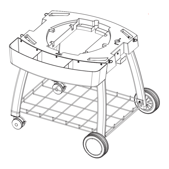
- Page 5 Fit the four LEG SUPPORTS (X & Y) as shown to brace the legs to the table us- Step 2 ing eight M6 x 20mm Bolts (L) and four M6 Nuts (N). Bolt the cylinder hook in place as shown using one M6 x 20mm Bolt (L) and one M6 Nut (N).
- Page 6 Fit the BOTTOM MESH (E) using four M6 X 20mm BOLTS (L). Step 3 Once all bolts are in place, fully tighten using a Phillips Head Screwdriver. Now tighten the bolts and nuts from the previous steps as well BOTTOM MESH (E) M6 X 20mm BOLT ALLEN KEY HEAD(L) 4 PCS...
- Page 7 Thread the AXLE (I) FIRST first through a WHEEL (H), then through a SPACER Step 4 (O), then through the legs, then through another SPACER (O), then through another WHEEL (H). Now fit the SPLIT PIN (P) into the axle, and clip the HUBCAPS (G) to the wheels. On the other two leg, fit WHEEL WITH LOCK (Z) on this leg and tighten firmly using SPANNER (S).
- Page 8 Turn the cart correct way up and lock each leg in place with one M6 X 20mm Step 5 BOLT (L) as shown. Tighten firmly using the ALLEN KEY (Q). Do not overtighten, the assembly will be very strong if these bolts are firm M6 X 20mm BOLT ALLEN KEY HEAD(L) 4PCS ALLEN KEY (Q) 1 PC...
- Page 9 Step 6 Hook the CONDIMENT TRAY (J) into place and secure firmly with five SELF TAPPING SCREWS (T). (INSIDE VIEW) CONDIMENT TRAY (J) FRONT SELF TAPPING SCREWS (T) 3PCS...
- Page 10 Step 7 Set all four leg locking pins to their “open” position by gently pulling outwards and twisting the rings to their “open” horizontal position as shown below. Place your Ziegler and Brown Triple Grill (SOLD SEPARATELY) in place on the table with the control panel at the front, cart wheels on the right as shown below.
- Page 11 Step 8 Refer to your Ziegler and Brown Triple Grill instruction manual for details on attaching and safety connecting the gas supply.
- Page 12 OPTIONAL ACCESSORIES STORAGE INSTRUCTIONS First Second Third Fourth Complete More Information? Need more information or assistance in any way? You can call your Barbeque Galore store where barbeque experts will be happy to help you. Just phone 1300 301 392 for your nearest store. www.barbequesgalore.com.au Or visit our website at:...
Need help?
Do you have a question about the ZG3GCARTK and is the answer not in the manual?
Questions and answers