Table of Contents
Advertisement
Quick Links
Advertisement
Table of Contents

Related Manuals for Cisco MDS 9396T


Summary of Contents for Cisco MDS 9396T
- Page 1 Cisco MDS 9396T Multilayer Fabric Switch Hardware Installation Guide First Published: 2018-05-08 Americas Headquarters Cisco Systems, Inc. 170 West Tasman Drive San Jose, CA 95134-1706 http://www.cisco.com Tel: 408 526-4000 800 553-NETS (6387) Fax: 408 527-0883...
- Page 2 Cisco and the Cisco logo are trademarks or registered trademarks of Cisco and/or its affiliates in the U.S. and other countries. To view a list of Cisco trademarks, go to this URL: https://www.cisco.com/go/trademarks. Third-party trademarks mentioned are the property of their respective owners. The use of the word partner does not imply a partnership relationship between Cisco and any other company.
-
Page 3: Table Of Contents
C H A P T E R 4 Installing the Cisco MDS 9396T Switch Preinstallation Installing the ESD Grounding Strap Unpacking and Inspecting the Switch Installation Options Cisco MDS 9000 Family Telco and EIA Shelf Bracket Cisco MDS 9396T Multilayer Fabric Switch Hardware Installation Guide... - Page 4 Connecting a Modem to a Console Port Connecting the Management Port Connecting to a Fibre Channel Port Removing and Installing SFP+ Transceivers Installing an SFP+ Transceiver Removing an SFP Transceiver Removing and Installing Cables into SFP Transceivers Cisco MDS 9396T Multilayer Fabric Switch Hardware Installation Guide...
- Page 5 Standard Power Cords Jumper Power Cords A P P E N D I X B Site Planning and Maintenance Records Site Preparation Checklist Contact and Site Information Chassis and Network Information Cisco MDS 9396T Multilayer Fabric Switch Hardware Installation Guide...
- Page 6 Contents Cisco MDS 9396T Multilayer Fabric Switch Hardware Installation Guide...
-
Page 7: Preface
C H A P T E R Preface This preface describes the audience, and conventions of the Cisco MDS 9396T Multilayer Fabric Switch Hardware Installation Guide. It also provides information on how to obtain related documentation. • Preface, on page 1 •... -
Page 8: Related Documentation
To find a document online, use the Cisco MDS NX-OS Documentation Locator at: http://www.cisco.com/c/en/us/td/docs/storage/san_switches/mds9000/roadmaps/doclocater.html Obtaining Documentation and Submitting a Service Request For information on obtaining documentation, using the Cisco Bug Search Tool (BST), submitting a service request, and gathering additional information, see What's New in Cisco Product Documentation. - Page 9 Preface Obtaining Documentation and Submitting a Service Request To receive new and revised Cisco technical content directly to your desktop, you can subscribe to the What's New in Cisco Product Documentation RSS feed. RSS feeds are a free service. Cisco MDS 9396T Multilayer Fabric Switch Hardware Installation Guide...
- Page 10 Preface Obtaining Documentation and Submitting a Service Request Cisco MDS 9396T Multilayer Fabric Switch Hardware Installation Guide...
-
Page 11: Product Overview
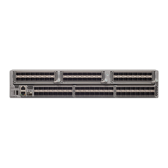
C H A P T E R Product Overview The Cisco MDS 9396T 32 Gbps 96 Port two rack unit Fibre Channel switch provides high speed Fibre Channel connectivity in the SAN. This switch offers analytics and telemetry capability built into its Application-Specific Integrated Circuit (ASIC) platform. - Page 12 Joint Test Action Group (JTAG) interface. Chassis Components Front View The following figure shows the front view of a Cisco MDS 9396T Switch: Figure 1: Front View of the Cisco MDS 9396T Switch Serial console port...
- Page 13 Power receptacle Fan module locking screw Power supply unit locking latch Grounding Point The rear of the Cisco MDS 9396T switch also contains the grounding point which is located under a label. Cisco MDS 9396T Multilayer Fabric Switch Hardware Installation Guide...
-
Page 14: Fan Modules
Linecard Expansion Module, on page 14 Fan Modules The Cisco MDS 9396T Multilayer Fabric switch supports two hot-swappable fan modules that allow the switches to continue to run if a fan module is removed, provided that the preset temperature thresholds have not been exceeded. -
Page 15: Power Supplies
Figure 4: Cisco MDS 9396T Fan Module Caution The Cisco MDS 9396T switch has internal temperature sensors that can shut down the system if the temperature at different points within the chassis exceeds certain safety thresholds. Temperature control within the chassis is dependant on airflow created by the fan modules;... -
Page 16: Switch Leds
Fan Modules, on page 8 section. Switch LEDs The following table describes the chassis activity LEDs for a Cisco MDS 9396T switch: Cisco MDS 9396T Multilayer Fabric Switch Hardware Installation Guide... - Page 17 • The operating system is not running. Green Solid On Both PSUs are installed and operating Solid On Either of the following conditions exists: • A PSU has failed. • A PSU has been removed. Cisco MDS 9396T Multilayer Fabric Switch Hardware Installation Guide...
- Page 18 Solid On Fan failure Green Solid on Fan module is operating Fan Status Faceplate of each Fan tray fan module health normally. Solid on The fan in the fan module has failed. Cisco MDS 9396T Multilayer Fabric Switch Hardware Installation Guide...
- Page 19 There is no activity. Right Blinking Indicates activity. Green The following table describes the Fibre Channel port LEDs for a Cisco MDS 9396T switch. Status State Solid Green The link is up. Regular Blinking Green The link is up and the port beacon is active.
-
Page 20: Linecard Expansion Module
Linecard Expansion Module Linecard Expansion Module The Linecard expansion module (LEM) is a pluggable expansion module for the Cisco MDS 9396T Switch. The switch is shipped with three LEMs. Each LEM has 16 32-Gbps ports that are automatically detected and enabled by the switch. - Page 21 A LEM should be removed only while replacing it with a new one in case of a fault condition. For more information on installing and removing the LEM, see the chapter Installing and Removing the Linecard Expansion Module. Cisco MDS 9396T Multilayer Fabric Switch Hardware Installation Guide...
- Page 22 Product Overview Linecard Expansion Module Cisco MDS 9396T Multilayer Fabric Switch Hardware Installation Guide...
-
Page 23: Cabinet And Rack Installation
Cabinet and Rack Requirements, on page 17 Cabinet and Rack Requirements This section provides the Cisco MDS 9000 Series switches requirements for the following types of cabinets and racks in an external ambient air temperature range of 0 to 40°C: •... -
Page 24: Requirements Specific To Perforated Cabinets
• The distance between the outside face of the front mounting rail and the outside face of the back mounting rail should be 23.5 to 34.0 in. (59.7 to 86.4 cm) to allow for installation with the Cisco rack mounting kit. -
Page 25: Requirements Specific To Solid-Walled Cabinets
• The open area of the floor air intake must be a minimum of 150 sq. in. (968 sq. cm). • The lowest piece of equipment should be installed at a minimum of 1.75 in. (4.4 cm) above the floor openings to prevent blocking the floor intake. Cisco MDS 9396T Multilayer Fabric Switch Hardware Installation Guide... - Page 26 Cabinet and Rack Installation Requirements Specific to Solid-Walled Cabinets Cisco MDS 9396T Multilayer Fabric Switch Hardware Installation Guide...
-
Page 27: Installing The Cisco Mds 9396T Switch
C H A P T E R Installing the Cisco MDS 9396T Switch This chapter describes how to install the Cisco MDS 9396T switch and its components. Note Before you install, operate, or service the system, see the Regulatory Compliance and Safety Information for the Cisco MDS 9000 Family for important safety information. -
Page 28: Preinstallation
The figures show how to cuff the ESD strap around the wrist and the ground cord that connects the cuff to the ground. ESD wrist straps are the primary means of controlling static charge on personnel. Cisco MDS 9396T Multilayer Fabric Switch Hardware Installation Guide... - Page 29 Installing the Cisco MDS 9396T Switch Installing the ESD Grounding Strap Note These images are for only representation purposes. The chassis' actual appearance and size may vary. Figure 7: Wearing the ESD Strap Cisco MDS 9396T Multilayer Fabric Switch Hardware Installation Guide...
-
Page 30: Unpacking And Inspecting The Switch
ESD socket is provided on the chassis. For the ESD socket to be effective, the chassis must be grounded through the power cable, the chassis ground, or the metal-to-metal contact with a grounded rack. Keep the shipping container in case the chassis requires shipping in the future. Cisco MDS 9396T Multilayer Fabric Switch Hardware Installation Guide... -
Page 31: Installation Options
Installing the Cisco MDS 9396T Switch Installation Options Note If you purchased Cisco support through a Cisco reseller, contact the reseller directly. If you purchased support directly from Cisco, contact Cisco Technical Support at this URL: http://www.cisco.com/c/en/us/support/web/tsd-cisco-worldwide-contacts.html Note The switch is thoroughly inspected before shipment. If any damage occurred during transportation or any items are missing, contact your customer representative immediately. -
Page 32: Cisco Mds 9000 Family Telco And Eia Shelf Bracket
This optional kit is not provided with the switch; to order the kit, contact your switch supplier. This section describes the procedure for installing a Cisco MDS 9396T switch in a rack or cabinet using the optional EIA Shelf Bracket Kit. - Page 33 Step 5 Insert the slider rails into the shelf brackets as shown in the above figure. Attach them to the rear rack-mounting rails using a minimum of four 12-24 or 10-24 screws. Cisco MDS 9396T Multilayer Fabric Switch Hardware Installation Guide...
- Page 34 Removing the Shelf Bracket Kit (Optional) The shelf bracket kit can be removed after the Cisco MDS 9396T switch has been installed in a four-post EIA rack, and both front rack-mount brackets and both C brackets are securely attached to the rack-mounting rails.
-
Page 35: Preinstallation Guidelines
Connection Guidelines for AC-Powered Systems To connect to the Cisco MDS 9396T switch AC power supply units to the site power source, follow these guidelines: • For power redundancy, each power supply should be connected to a separate power feed (at a minimum, separate branch circuits). -
Page 36: Installing The Switch
• 12-24 screws: 30 in-lb (3.39 N·m) Installing the Switch This section describes how to use the rack-mount kit to install the Cisco MDS 9396T switch into a cabinet or rack that meets the requirements described in the Cabinet and Rack Requirements, on page 17 section. -
Page 37: Attaching The Front-Mount Brackets To The Chassis
• You need to attach a right-angled bracket to each side of the chassis. This bracket holds the chassis in place on a four post rack. • You must have a Phillips-head torque screwdriver. Cisco MDS 9396T Multilayer Fabric Switch Hardware Installation Guide... -
Page 38: Installing The Switch
• The color of the stripe on fan trays and the color of the latch on power supplies determines which end of the switch must be positioned in the cold aisle as follows: Cisco MDS 9396T Multilayer Fabric Switch Hardware Installation Guide... - Page 39 Chassis stops for holding the chassis (installed by the hot aisle) Cisco MDS 9396T Multilayer Fabric Switch Hardware Installation Guide...
-
Page 40: Grounding The Switch
• Wire stripping tool to remove the insulation from the grounding wire. Step 1 Use a wire stripping tool to remove approximately 0.75 inch (19 mm) of the covering from the end of the grounding wire. Cisco MDS 9396T Multilayer Fabric Switch Hardware Installation Guide... -
Page 41: Installing And Remvoing Components
Gently slide the LEM into the LEM bay till it clicks into place with the help of the Linecard Expansion Module ejector. Step 4 Secure the Linecard Expansion Module ejector with the locking screw. Cisco MDS 9396T Multilayer Fabric Switch Hardware Installation Guide... -
Page 42: Removing The Linecard Expansion Module
Step 5 Physically insert the linecard expansion blank module to ensure proper system cooling. Installing and Removing AC Power Supplies This section provides instructions for installing and removing the AC power supplies for the Cisco MDS 9396T switch. Installing Power Supplies... -
Page 43: Removing Power Supplies
Installing and Removing Fan Modules This section provides instructions for installing and removing the fan modules for the Cisco MDS 9396T switch. You can replace one of the two fan modules even when the switch is operating so long as you perform the replacement within one minute of removing the old fan module. -
Page 44: Removing A Fan Module
Caution The Cisco MDS 9000 Family has internal temperature sensors that can shut down the system if the temperature at different points within the chassis exceed certain safety thresholds. To accurately monitor the system temperature, the temperature sensors require sufficient airflow through the chassis. -
Page 45: Connecting The Cisco Mds 9396T Switch
• Powering Up the Switch, on page 46 Preparing for Network Connections When preparing your site for network connections to the Cisco MDS 9396T switch, consider the following for each type of interface: • Cabling required for each interface type •... -
Page 46: Connecting The Console Port To A Pc
• Perform initial switch configuration • Perform password recovery Connecting the Console Port to a PC You can connect the console port to a PC serial port for local administrative access to the Cisco MDS 9396T switch. Note The PC must support VT100 terminal emulation. The terminal emulation software—frequently a PC application such as HyperTerminal Plus—makes communication between the Cisco MDS 9396T switch and your PC... -
Page 47: Connecting The Management Port
The autosensing 10/100/1000 Mbps Ethernet management ports are located on the left side of the front panel (labeled MGMT ETH0 and MGMT ETH1), below the console port. MGMT ETH0 is the default Ethernet management port (interface mgmt0). This port is used for out-of-band management of the Cisco MDS 9396T switch and data streaming to remote receivers. -
Page 48: Connecting To A Fibre Channel Port
SFP+ transceivers to prevent damage to the cable or transceiver. Note Use only Cisco SFP+ transceivers on the Cisco MDS 9396T switch. Each Cisco SFP+ transceiver is encoded with model information that enables the switch to verify that the SFP+ transceiver meets the requirements for the switch. -
Page 49: Installing An Sfp+ Transceiver
1. Record the cable and port connections for later reference. 2. Press the release latch on the cable, grasp the connector near the connection point, and gently pull the connector from the transceiver. Cisco MDS 9396T Multilayer Fabric Switch Hardware Installation Guide... -
Page 50: Removing And Installing Cables Into Sfp Transceivers
Remove the dust cover from the cable end of the transceiver. Step 4 Align the cable connector with the transceiver and insert the connector into the transceiver until it clicks into place. Cisco MDS 9396T Multilayer Fabric Switch Hardware Installation Guide... -
Page 51: Removing A Cable From An Sfp Transceiver
SFP transceivers and fiber-optic cables must be kept clean and dust-free to maintain high signal accuracy and prevent damage to the connectors. Attenuation (loss of light) is increased by contamination, and it should be kept below 0.35 dB. Follow these maintenance guidelines: Cisco MDS 9396T Multilayer Fabric Switch Hardware Installation Guide... -
Page 52: Powering Up The Switch
3. Verify that the LED is on and green. If the LED is off, check the AC power source circuit breaker to be sure that it is turned on. Step 2 If you are using the power supply (n+1) redundancy, you must connect the second power supply as follows: Cisco MDS 9396T Multilayer Fabric Switch Hardware Installation Guide... - Page 53 3. Verify that the LED is on and green. If the LED is off, check the AC power source circuit breaker to be sure that it is turned on. Cisco MDS 9396T Multilayer Fabric Switch Hardware Installation Guide...
- Page 54 Connecting the Cisco MDS 9396T Switch Powering Up the Switch Cisco MDS 9396T Multilayer Fabric Switch Hardware Installation Guide...
-
Page 55: Technical Specifications
Switch Specifications, on page 49 • Power Specifications, on page 50 Switch Specifications The following table lists the environmental specifications for the Cisco MDS 9396T switch. Table 1: Environmental Specifications for the Cisco MDS 9396T switch Description Specification Temperature, ambient operating 32 to 104°F (0 to 40°C) -
Page 56: Power Specifications
(15.2 cm) between two chassis to prevent overheating. Power Specifications General Power Supply Specifications The following table lists the specifications for the Cisco MDS 9396T switch AC power supply. AC Input Power Specification AC input voltage 90V to 305V... -
Page 57: Power Supply Requirements Specifications
Connection Guidelines for AC-Powered Systems For connecting the Cisco MDS 9396T switch AC power supplies to the site power source, follow these basic guidelines: • Each power supply should have its own dedicated branch circuit. - Page 58 Technical Specifications Connection Guidelines for AC-Powered Systems Cisco MDS 9396T Multilayer Fabric Switch Hardware Installation Guide...
-
Page 59: Appendix A Cable And Port Specifications
A P P E N D I X Cable and Port Specifications This appendix includes the cables and connectors used with the Cisco MDS 9396T Multilayer Fabric Switch. Caution We strongly recommend that power cable runs and other potential noise sources be located as far away as practical from network cabling that terminates on Cisco equipment. -
Page 60: Console Port
(depending on your computer serial port) to connect the console port to a computer running terminal emulation software. Console Port Pinouts The following table lists the pinouts for the console port on the Cisco MDS 9396T Switch. Table 4: Console Port Pinouts Signal 1. -
Page 61: Connecting The Console Port To A Computer Using The Db-9 Adapter
MGMT 10/100/1000 Ethernet Port Use a modular, RJ-45, straight-through UTP cable to connect the 10/100/1000 management Ethernet port to external hubs and switches. To connect to a router, use a crossover cable. Cisco MDS 9396T Multilayer Fabric Switch Hardware Installation Guide... - Page 62 The following figure shows a schematic of the 10/100/1000BASE-T cable. Figure 16: Twisted-Pair 10/100/1000BASE-T Cable Schematic The following table lists the connector pinouts and signal names for a 10/100BASE-T management port (MDI) cable. Cisco MDS 9396T Multilayer Fabric Switch Hardware Installation Guide...
-
Page 63: Supported Power Cords And Plugs
Supported Power Cords and Plugs Each switch power supply unit requires one power cord. Cisco approved cords may be ordered with the product. Standard power cords with a country specific plug can be used with wall outlets. Jumper power cords can be used with cabinet outlets.The user may also source their own power cords for the product, as long as... -
Page 64: Standard Power Cords
Standard Power Cords Cisco standard power cords for the Cisco MDS 9396T switch have an IEC C15 connector on the outlet end of the cord and a country specific plug on the inlet end of the cord. To see the list of supported standard power... -
Page 65: Appendix B Site Planning And Maintenance Records
A P P E N D I X Site Planning and Maintenance Records This section includes a site planning checklist and maintenance records to use when installing the Cisco MDS 9396T Multilayer Fabric Switch. Note For information about how to query the switch for configuration information, see the... - Page 66 Grounding evaluation: • Circuit breaker size • CO ground (AC- powered systems) Cable and interface equipment evaluation: • Cable type • Connector type • Cable distance limitations • Interface equipment (transceivers) Cisco MDS 9396T Multilayer Fabric Switch Hardware Installation Guide...
-
Page 67: Contact And Site Information
Data center location Floor location Address (line 1) Address (line 2) City State Zip code Country Chassis and Network Information Use the following worksheets to record chassis and network information. Contract Number : Cisco MDS 9396T Multilayer Fabric Switch Hardware Installation Guide... - Page 68 Site Planning and Maintenance Records Site Planning and Maintenance Records Chassis Serial Number: Product Number: Switch IP address Switch IP netmask Host name Domain name IP broadcast address Gateway/router address DNS address Modem telephone number Cisco MDS 9396T Multilayer Fabric Switch Hardware Installation Guide...
Need help?
Do you have a question about the MDS 9396T and is the answer not in the manual?
Questions and answers