
Related Manuals for TEL AFA 500


Summary of Contents for TEL AFA 500
- Page 1 AFA 500 FUME HOOD ALARMS Operating and Instruction Manual Model AFA 500 – Mk2 • Built-in or Remote sensor • 2 Relay inputs • 1 Relay output • Com port Used for alarm indication and monitoring on Fume Hoods Issue: Jan 08...
-
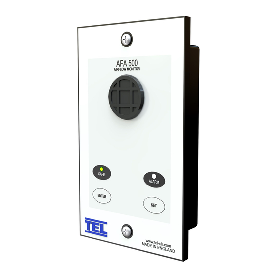
Page 2: Operator Display Panel
OPERATOR DISPLAY PANEL Built-in AIRFLOW SENSOR Not visible when Remote AIRFLOW SENSOR is used LED indicators Function buttons Calibration. ENTER – also used as Mute button for audible alarm... -
Page 3: Connection Details
REFER TO INSTALLATION 220V 50Hz -- Euro 2-pin INSTRUCTIONS Relay output 2 BEFORE 120V 60Hz -- USA 2-pin Rated 110V CONNECTING 2A AC1 AFA 500 15V DC POWER SUPPLY INPUT OPTIONAL Flying lead with plug REMOTE COMMS connection for PCB... -
Page 4: General Description
1.1 General Description All systems comprise of the following components :- 1 – AFA 500 Alarm unit, 1 – AC power supply If the Sash Alarm System option is ordered there will also be a sash micro switch or proximity switch. -
Page 5: Night Setback
External Connections -- the alarm unit will have the following connection points :- Input 1 --- volt free relay input – ( close contact to activate the input ) This input is configured as :- NIGHT SETBACK Output R1 --- volt free relay output - ( contact closes on activation ) This input is configured as :- LOW AIR ALARM Sash High Input --- a. -
Page 6: Alarm Configuration / Calibration
1.2 Alarm Configuration / Calibration The alarm is supplied with a factory configuration. The only part of the configuration that can be changed is the setting for the Sash High repeat timer time delay and the percentage figure for the Low Air alarm point when using the two point calibration mode-- if required these can be changed by connection to a Laptop or PC via the RS232 com port. -
Page 7: Events / Actions
1.4 Events / actions Safe airflow Airflow above alarm level ( eg > 80 fpm ) • Green LED on • Low airflow Airflow below alarm level for longer than the low air delay time ( 5 secs) • Red LED on ( Not flashing ) •... - Page 8 Follow the instructions below for installing and commissioning the unit. :- Before connecting the unit it is important to decide on the type of calibration that is to be used on the installation. The two methods are described in section 1.2 Alarm Configuration / Calibration above.
-
Page 9: Calibration Notes
a. Open the Sash to the normal operating height and adjust the face velocity to the normal operating value using a calibrated instrument to check the value. b. Press and hold the Enter button for 5 secs to go into the Calibration mode. This is indicated by both Red and Green LEDS flashing on/off together with the audible alarm sounding ( ‘Beep’... - Page 10 However because the AFA 500 does not have a digital display of the face velocity we can not enter particular values into the alarm. For this...
- Page 11 When using the Duct Connection method the ¼ inch connection tube acts as a flow restrictor ( due to the higher pressure in the duct ). Use a 6ft tube for pressures below 0.4 ins Wg and a 12ft tube for higher pressures...
-
Page 12: Installation Notes
It is very important to position the AFA 500 or SM6 airflow sensor in the correct position to give long term stable reading of the face velocity. Please read the INSTALLATION NOTES below and if in doubt contact us for further advice. -
Page 13: Typical Wiring Diagram
REFER TO INSTALLATION 220V 50Hz -- Euro 2-pin INSTRUCTIONS Relay output 2 BEFORE 120V 60Hz -- USA 2-pin Rated 110V CONNECTING 2A AC1 AFA 500 15V DC POWER SUPPLY INPUT OPTIONAL Flying lead with plug REMOTE COMMS connection for PCB... - Page 14 REFER TO INSTALLATION 220V 50Hz -- Euro 2-pin INSTRUCTIONS Relay output 2 BEFORE 120V 60Hz -- USA 2-pin CONNECTING Rated 110V 2A AC1 AFA 500 15V DC POWER SUPPLY OPTIONAL INPUT Flying lead with plug COMMS REMOTE connection for PCB...
-
Page 15: Limitation Of Warranty And Liability
6.0 Limitation of Warranty and Liability Seller warrants that this product, under normal use and service as described in the operator’s manual shall be free from defects in workmanship and material for a period of twelve (12) months, or the length of time specified in the operator’s manual, from the date of shipment to the customer.
Need help?
Do you have a question about the AFA 500 and is the answer not in the manual?
Questions and answers