
Related Manuals for TEL AFA 1000

Summary of Contents for TEL AFA 1000
- Page 1 AFA 1000 FUME HOOD ALARMS Operating and Instruction Manual Model AFA1000 / 1 • Digital display • 1 Output relay • 3 Input relays • Com port Used for alarm indication and monitoring on Fume Hoods 1/MK3/FH/USPSU 250804...
-
Page 2: Table Of Contents
Table of contents Section Description Page Operator display panel Connection details General description – overview 5 to 8 Installation Start-up / Calibration 9 to 11 Monitor configuration Events – actions 12 to 15 Dimensions 16 to 17 In-line sensor installation 18 to 19 Wiring diagram Spares... -
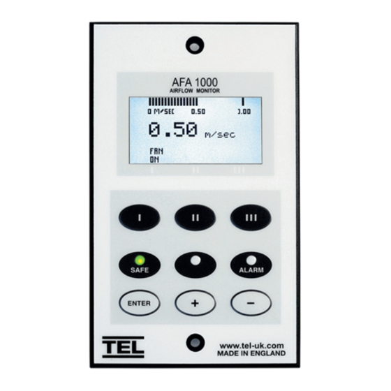
Page 3: Operator Display Panel
1.0 Operator Display Panel Velocity Bar Graph or Alarm Time Line Velocity display fpm or m/sec LED indicators Function and up/down buttons for Menu Configuration and Calibration. ENTER – also used as Mute button for audible alarm... -
Page 4: Connection Details
REFER TO MADE IN ENGLAND INSTALLATION INSTRUCTIONS www.tel-uk.com BEFORE CONNECTING AFA 1000 USA 120V / 15V DC Plug – in power adapter for 120V socket Flying lead with RJ11 Power requirement - 110mA plug connection for PCB @ 120v AC Supply... -
Page 5: General Description - Overview
3.0 General Description All systems comprise of the following components :- 1 – In-line Airflow Sensor, 1 – AFA1000 Alarm unit, 1 – AC power supply If the Sash Alarm System option is included there will also be a sash micro switch or proximity switch. - Page 6 High Air - will be displayed if the airflow is more than the High air alarm point. This display will alternate on/off with the velocity reading Set-back - will be displayed if the night set-back function is activated ( when enabled ) This display will alternate on/off with the velocity reading Disabled - will be displayed if the alarm disable function is activated ( when...
- Page 7 External Connections -- the alarm unit has the following connection points :- Input 1 --- volt free relay input configurable for normally closed or normally open relays This input can be configured as :- Alarm disable Night set-back External alarm Sash High High / Low Input 2 --- volt free relay input configurable for normally closed or normally...
-
Page 8: Installation
4.0 Installation Follow the instructions below for installing the unit. :- 1. Fit the alarm to the Fume Hood using the cut-out details provided with the unit --- see page 16 to 17 2. Fit the airflow sensor to the Fume Hood using the cut out and installation details provided --- see page 18 3. - Page 9 A higher value is taken with the sash partially closed and this is also ‘captured’ by the alarm. From these two known points the alarm will track the face velocity over the whole range of the hood face velocities Before starting the calibration of the alarm please read the ‘Calibration Notes ‘...
- Page 10 5.1 Calibration Notes :- 1. When using a standard Fume Hoods with Vertical Sliding sashes open the sash to the normal max safe working height for the Low Air sample. For the Higher Air sample close the sash to approx 50% of the opening used for the Lower Air sample.
-
Page 11: Monitor Configuration
6.0 Monitor Configuration The configuration of the various functions and the calibration of the alarm face velocity display is menu driven. Access to the Calibration and Configure menu will be via separate passwords (4 digit numbers ). The numbers are factory set to 0000 and 0000 . -
Page 12: Events - Actions
7.0 Events / actions Normal airflow • Meter reading above warning level ( e.g. > 90fpm ) • Green LED on Warning airflow • Meter reads between warning level and air fail level ( e.g. > 80fpm and < 90fpm ) •... - Page 13 High airflow If configured :- • High Air toggles on / off with display • Audible alarm sounds – can be muted via Enter pushbutton Sash High • When the input configured as Sash High is activated • Amber LED on •...
- Page 14 High / Low • When input configured as High/Low is activated • Display Icon shows High or Low • High / Low relay operates ( if configured ) This function is designed for two speed fan operation or two position damper operation switched via a micro switch or proximity switch activated at a given position on the sash.
- Page 15 Alarm disable • When input configured as Alarm disable is activated • Alarm disabled is displayed • Red LED on ( Flashing) • Audible alarm muted • Mute Icon shown on display Audible alarm Mute • When the audible alarm is muted via the Enter button - an Icon ( horn with forward slash) is shown on the display.
-
Page 16: Dimensions
8.0 Dimensions Alarm Panel Dimensions 1.59 ″ 1.59 ″ (40.5mm) (40.5mm) 1.14″ (29mm) 2.91 ″ 4.37 ″ 5.2 ″ (74mm) (111mm) (132mm) 1.14″ (29mm) 3.19″ ″ 1.89 (81mm) ″ ″ (48mm) 0.75 0.38 (19mm) (9.75mm) Front Rear Side View View View Panel Cutout 2 x Fixing Holes... - Page 17 Concept or Pioneer Fume Hood Vent Tube Hole Airflow Alarm SafeAire Fume Hood Vent Tube Hole Airflow Alarm...
- Page 18 9.0 In – line Airflow Sensor Installation The in-line sensor kit comprises of the following components Select the correct length of Hose to suit the installation . The Cross Hatch Washer is fixed inside of the female coupling.
- Page 19 It is very important to position the In-line airflow sensor in the correct position to give long term stable reading of the face velocity. Please read the INSTALLATION NOTES below and if in doubt contact us for further advice. INSTALLATION NOTES :- 1.
-
Page 20: Wiring Diagram
REFER TO MADE IN ENGLAND INSTALLATION INSTRUCTIONS www.tel-uk.com BEFORE CONNECTING AFA 1000 USA 120V / 15V DC Plug – in power adapter for 120V socket Flying lead with RJ11 Power requirement – plug connection for PCB and SM6 airflow sensor... - Page 21 11.0 Spare Parts List Item Description Part Number AFA1000 AFA1000/1/Mk3/FH/USPSU 62199 SM6 SIL In-line FH Airflow sensor SM6 / SIL / FH with 2m RJ11 cable Flexible tube Flexible tube 30” Adaptorflex 30” Cross Hatch Washer Cross Hatch washer –white CHW /Wh Front Post 1”...
-
Page 22: Limitation Of Warranty And Liability
726 McKinley Ave. Libertyville, Illinois 60048 : 847- 680-9930 : 847-680-9938 Phone e-mail: info@hollandsafety.com web site: www.hollandsafety.com Temperature Electronics Ltd Export sales :- : + 44 161 257 2541 : + 44 161 228 8817 e-mail: xportsales@exportsales.com web site: www.tel-uk.com...
Need help?
Do you have a question about the AFA 1000 and is the answer not in the manual?
Questions and answers