Table of Contents
Advertisement
Flame Safeguard Programming Controls
OPTIONAL
202050C
COVER
OPTIONAL HEAVY DUTY
COVER (PART NO.
202050C OR 139695C)
IMPORTANT
Applications, Features, Specifications (including
dimension drawings), Operation (including
schematics and bar charts), and Wiring Diagrams
are included in these Specifications for models of
the R4140G, L, and M: R4140G—60-2337;
R4140L—60-2339; R4140M—60-2340.
Copyright © 1996 Honeywell Inc. • All Rights Reserved
RESET BUTTON
TIP JACK
PLUG-IN
AMPLIFIER
RELAY/TIMER
COVER
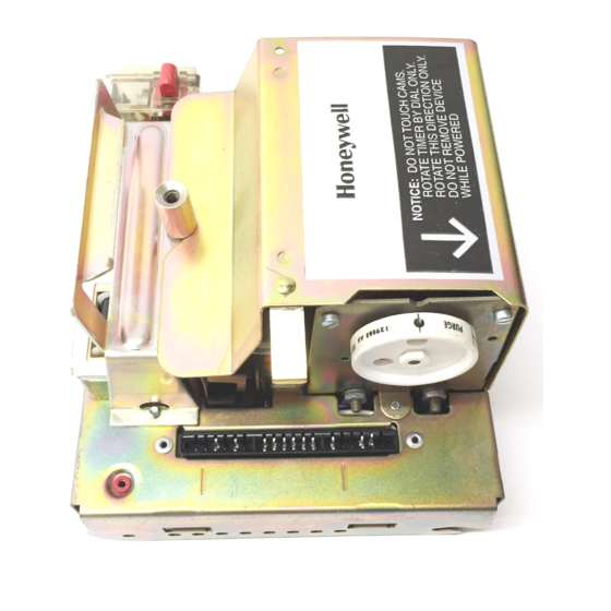
Fig. 1. Components of R4140G and R4140M Programmers.
RESET BUTTON
PLUG-IN
FLAME SIGNAL
AMPLIFIER
FLAME SIGNAL
METER JACK
RELAY/TIMER
COVER
Fig. 2. Components of R4140L Programmers.
R4140G,L and M
HANDLE
TIMER
TIMER DIAL
RELAY
FLAME SIGNAL
2K
METER JACK
CHASSIS RETAINING
HANDLE
TIP JACK
SCREW
TIMER
TIMER DIAL
RELAY
2K
RELAY 1K
Installation ........................................................................... 2
Checkout ............................................................................. 11
Troubleshooting .................................................................. 18
Service Information ............................................................. 27
Testing And Maintenance .................................................... 28
INSTALLATION INSTRUCTIONS
CHASSIS RETAINING
SCREW
SAFETY SWITCH
BUTTON
CHASSIS
HINGE
TIMER
BRACKET (2)
MOTOR
RELAY
1K
M10053
RELAY 4K
SAFETY SWITCH
BUTTON
CHASSIS
HINGE
BRACKET (2)
TIMER
RELAY
MOTOR
M7959
3K
Contents
60-0770-2
Advertisement
Table of Contents
Troubleshooting

Related Manuals for Honeywell R4140G


Summary of Contents for Honeywell R4140G
- Page 1 TIMER BRACKET (2) TIMER DIAL RELAY RELAY/TIMER MOTOR RELAY FLAME SIGNAL COVER M10053 METER JACK Fig. 1. Components of R4140G and R4140M Programmers. CHASSIS RETAINING HANDLE RESET BUTTON TIP JACK SCREW RELAY 4K PLUG-IN SAFETY SWITCH FLAME SIGNAL BUTTON AMPLIFIER...
-
Page 2: Installation
R4140G, L AND M FLAME SAFEGUARD PROGRAMMING CONTROLS INSTALLATION Weather The R4140 is not designed to be weather tight. If it is installed outdoors, it must be protected. When Installing this Product... 1. Read these instructions carefully. Failure to follow them... - Page 3 NOTE: Table 1 lists the flame detection systems available Refer to the appropriate wiring diagram in the for use with R4140 Programmers. Make sure you Specifications for the R4140G,L or M. Follow the burner are using the correct combination of amplifier and manufacturer’s wiring diagram, if provided.
- Page 4 R4140G, L AND M FLAME SAFEGUARD PROGRAMMING CONTROLS After checking all wiring circuits, perform this checkout before Special Considerations for a C7012E or F installing the programmer on the subbase. These tests The R4140 provides two sources of power for a C7012E or F...
- Page 5 R4140G, L AND M FLAME SAFEGUARD PROGRAMMING CONTROLS Table 2. Static Tests of External Devices (Continued). Test R4140 Test Normal If Operation is Abnormal, Models Jumpers Voltmeter Operation Check the Items Listed Below Models with None 16-L2 Line voltage at terminal 16.
- Page 6 R4140G, L AND M FLAME SAFEGUARD PROGRAMMING CONTROLS Table 2. Static Tests of External Devices (Continued). Test R4140 Test Normal If Operation is Abnormal, Models Jumpers Voltmeter Operation Check the Items Listed Below All R4140L L18 and 13-L2 Firing rate motor drives closed;...
- Page 7 R4140G, L AND M FLAME SAFEGUARD PROGRAMMING CONTROLS NOTE: If installing a small amplifier, align its ends with Removing and Replacing the Relay/Timer the two scribe marks alongside the receptacle Cover (Fig. 4) on the programmer. Push in the amplifier until the circuit board is fully CAUTION inserted into the receptacle.
- Page 8 A system can be upgraded from on-off to modulating by Installing Jumper on Back of Programmer (Fig. 6) replacing an R4140M with an R4140G (Fig. 7). A system can Some R4140G, L, and M models have provisions for be upgraded to meet Factory Mutual and Industrial Risk...
- Page 9 DAMPER CONTROL FROM TERMINALS 10 AND L2, AND REMOVE JUMPER ADD LOW FIRE SWTICH (IF NOT ALREADY CONNECTED). WIRE FROM TERMINALS 11 AND 12. Fig. 7. Sample block diagram of field wiring for replacing an R4140M with an R4140G. 60-0770—2...
- Page 10 R4140G, L AND M FLAME SAFEGUARD PROGRAMMING CONTROLS REPLACING AN R4140M OR G WITH AN R4140L FOR DIRECT SPARK IGNITION (OIL OR GAS) FOR DIRECT SPARK IGNITION (OIL OR GAS) ON MODELS WITH INTERMITTENT ON MODELS WITH INTERRUPTED PILOT/IGNITION ON TERMINAL 6...
-
Page 11: Checkout
R4140G, L AND M FLAME SAFEGUARD PROGRAMMING CONTROLS CHECKOUT 6. Manometer (or pressure gauge) to measure pilot gas pressure. 7. Thermometer or thermocouple to measure temperature WARNING at the flame detector(s). 8. Orifice plates (aperture disks) or filters, as necessary, to FIRE OR EXPLOSION HAZARD adjust sensitivity of flame detector(s). - Page 12 Check the detector wiring for defects including: Use a Honeywell W136A Test Meter. (If a W136A is not — incorrect connections. available, a microammeter with a 0 to 25 uA dc range —...
- Page 13 R4140G, L AND M FLAME SAFEGUARD PROGRAMMING CONTROLS For all other detectors, clean the detector lens, filter, NOTE: Low fuel pressure limits, if used, could be open. If viewing window, and inside of the sight pipe, as so, bypass them with jumpers during this check.
- Page 14 R4140G, L AND M FLAME SAFEGUARD PROGRAMMING CONTROLS On the subbase, jumper terminal L1 to the If the main burner flame is not established within five sec- ignition terminal (5, 6, or 18). Refer to the onds, or within the normal lightoff time specified by the...
- Page 15 R4140G, L AND M FLAME SAFEGUARD PROGRAMMING CONTROLS Let the timer dial advance through PREPURGE. When IMPORTANT the IGN part of the dial is opposite the index notch, Make sure all readings are in the required ranges watch for ignition spark and listen for the click of the before proceeding.
- Page 16 R4140G, L AND M FLAME SAFEGUARD PROGRAMMING CONTROLS NOTE: This step requires two people—one to open the Hot Refractory Saturation Test (All Infrared manual valve(s) and one to watch for ignition. Detectors) If the main burner flame is not established within five...
- Page 17 R4140G, L AND M FLAME SAFEGUARD PROGRAMMING CONTROLS (Burn a solid instead of a liquid, or a liquid instead of a gas.) Flame Signal with Hot Combustion Chamber When the maximum refractory temperature is reached, close (All Installations) all manual fuel shutoff valves, or open the electrical circuits of all automatic fuel valves.
-
Page 18: Troubleshooting
R4140G, L AND M FLAME SAFEGUARD PROGRAMMING CONTROLS Reset the Lockout switch, if tripped. Opening of a Lockout Interlock (R4140L Only). Close the master switch. Make sure all manual fuel shutoff valves are Start the system with a call for heat. (Raise the open;... - Page 19 Refer to the Step-By-Step Operation for the appropriate shown that the deposits are not heavy enough to R4140 model in the Operation section of the R4140G,L or M cause ignition failure. Determine exactly at what Specifications. Observe the operation carefully to determine point in the operating sequence the trouble occurs the point where the trouble occurs.
- Page 20 Check Airflow switch; replace if necessary. D. Programmer stops during 1. For an R4140G or M, proceed to step 3. 1. If switch is open: prepurge and does not On an R4140L only, check that the external a. Check High Fire switch; replace if continue sequence.
- Page 21 R4140G, L AND M FLAME SAFEGUARD PROGRAMMING CONTROLS Table 5. Troubleshooting Chart (Continued) . Symptom Test Possible Cause/Correction D. Programmer stops during 4. If an external Low Fire switch is used, 4. If switch is open: prepurge and does not check that it is closed.
- Page 22 R4140G, L AND M FLAME SAFEGUARD PROGRAMMING CONTROLS Table 5. Troubleshooting Chart (Continued) . Symptom Test Possible Cause/Correction 3. If main burner (or second stage burner) still 3. Make sure that external circuits are wired G. Pilot (or first stage burner) does not light, close all manual fuel shutoff correctly;...
- Page 23 Table 5. Troubleshooting Chart (Continued) . Symptom Test Possible Cause/Correction J. Burner stays at low fire 1. For an R4140G or L, check 4-wire firing 1. a. Make sure that external circuits are during Run period. (Not rate switching circuitry. wired correctly; replace deteriorated applicable for R4140M model leadwires.
- Page 24 R4140G, L AND M FLAME SAFEGUARD PROGRAMMING CONTROLS Table 5. Troubleshooting Chart (Continued) . Symptom Test Possible Cause/Correction N. Relay 2K stays in at end of 1. Perform the Flame Relay (2K) Hold-In 1. Follow instructions in the Flame Relay (2K) cycle.
- Page 25 — If the problem still exists, replace the programmer. NOTE: As soon as 2K pulls in: on an R4140G All standard models (R7247A, R7248A, and or M, relay 1K drops out and the timer R7249A).
- Page 26 NOTE: As soon as 2K pulls in: Let the timer complete its revolution and set the — On an R4140G or M, relay 1K drops timer switch to the NORM position. out and the timer starts to run. Open the master switch and remove the —...
-
Page 27: Service Information
Always keep the burner and fuel mixture adjusted M7969 according to the burner manufacturer recommendations. Fig. 15. Location of R4140G and R4140M relay contact Keep the flame detection system adjusted for the (front view). smoothest, most reliable operation recommended by the burner manufacturer. -
Page 28: Testing And Maintenance
R4140G, L AND M FLAME SAFEGUARD PROGRAMMING CONTROLS Minimum Inspection and Testing Schedule The following inspection and testing schedule is taken from the ASME safety code, ASME CSD-1. TIMER CONTACTS CM-102 Minimum Schedule Daily For high pressure boiler, test low water fuel MOTOR cutoff and alarm. - Page 29 R4140G, L AND M FLAME SAFEGUARD PROGRAMMING CONTROLS Item Frequency Accomplished By Remarks Gauges, Monitors, and Indicators Daily Operator Make visual inspection and record readings in log. Instrument and Equipment Settings Daily Operator Make visual check against factory recommended specifications.
- Page 30 R4140G, L AND M FLAME SAFEGUARD PROGRAMMING CONTROLS 60-0770—2...
- Page 31 R4140G, L AND M FLAME SAFEGUARD PROGRAMMING CONTROLS 60-0770—2...
- Page 32 R4140G, L AND M FLAME SAFEGUARD PROGRAMMING CONTROLS Automation and Control Solutions Honeywell Asia Pacific Inc. Honeywell International Inc. Honeywell Limited-Honeywell Limitée Room 3213-3225 1985 Douglas Drive North 35 Dynamic Drive Sun Hung Kai Centre Golden Valley, MN 55422 Scarborough, Ontario M1V 4Z9 No.