Table of Contents
Advertisement
Quick Links
IB-30B002
LUMINARY SERIES MOTION CONTROLLER
FEBRUARY 2014
LUMINARY CONTROLLER
LMC-400
INSTRUCTION BOOK
INDUSTRIAL INDEXING SYSTEMS, Inc.
Revision - 0
Approved By:
Proprietary information of Industrial Indexing Systems, Inc. furnished for customer use only.
No other uses are authorized without the prior written permission of
Industrial Indexing Systems, Inc.
Advertisement
Table of Contents

Related Manuals for Industrial Indexing Systems LMC-400

Summary of Contents for Industrial Indexing Systems LMC-400
- Page 1 LUMINARY CONTROLLER LMC-400 INSTRUCTION BOOK INDUSTRIAL INDEXING SYSTEMS, Inc. Revision - 0 Approved By: Proprietary information of Industrial Indexing Systems, Inc. furnished for customer use only. No other uses are authorized without the prior written permission of Industrial Indexing Systems, Inc.
-
Page 2: Table Of Contents
INDUSTRIAL INDEXING SYSTEMS, Inc. IB-30B002 LUMINARY SERIES MOTION CONTROLLER USER’S GUIDE TABLE OF CONTENTS List of Illustration..............................v Introduction ................................vi SECTION 1 - OVERVIEW Identifying the Luminary Controller..................1 - 1 Luminary Controller Mounting Plates……….………………………………………………. 1 - 2 SECTION 2 - DESCRIPTION Components.........................2 - 2... - Page 3 IB-30B002 INDUSTRIAL INDEXING SYSTEMS, Inc. USER’S GUIDE LUMINARY SERIES MOTION CONTROLLER SECTION 5 - STATUS & ERROR CODES Controller Status ........................5 - 1 Device Port Status Display ....................5 - 3 SECTION 6 - INSTALLATION GUIDELINES General..........................6 - 1 Enclosure Cabinet Requirements..................6 - 1 Mounting the System Unit....................6 - 1...
-
Page 4: List Of Illustration
LUMINARY SERIES MOTION CONTROLLER USER’S GUIDE LIST OF ILLUSTRATIONS SECTION 1 - OVERVIEW SECTION 2 - DESCRIPTION Figure 2.1 LMC-400 Layout.....................2 - 1 SECTION 3 – LUMINARY CONTROLLER SPECIFICATIONS SECTION 4 - LUNIMARY WIRING Figure 4.1 Luminary Controller Wiring..................4 - 2 Figure 4.2 Input Wiring......................4 - 4... -
Page 5: Introduction
The LMC-400 embodies a blend of open architecture features with a true real-time operating system. The result is a state-of-the art performance and superior connectivity to other systems and network components. -
Page 6: Section 1 - Overview
SECTION 1 - OVERVIEW This manual is organized so that information is easy to find and easy to use. It begins by detailing how to identify the LMC-400 Controller. This section is followed by a general description of the product and its components. -
Page 7: Luminary Controller Mounting Plates
IB-30B002 INDUSTRIAL INDEXING SYSTEMS, Inc. USER’S GUIDE LUMINARY SERIES MOTION CONTROLLER LUMINARY CONTROLLER MOUNTING PLATES The Luminary Controller mounting plate drawings are shown below. Other options may be available. 0.13 [ 3.2] (5 PL ACES) 5.50 [139.7] 0.29 [7.5] 4.38 [111.1] 3.91 [99.3]... -
Page 8: Section 2 - Description
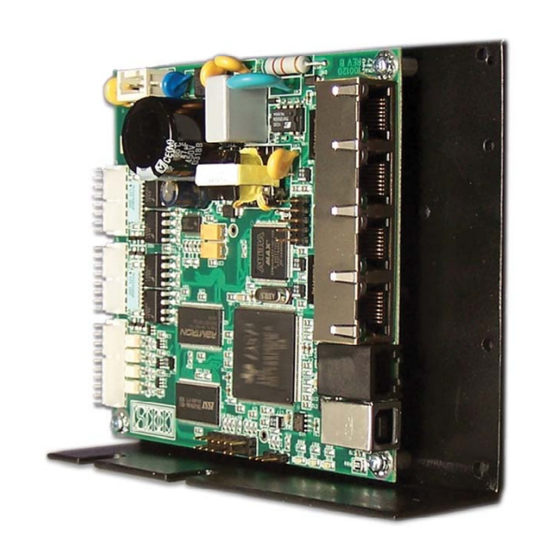
USER’S GUIDE SECTION 2 - DESCRIPTION The Luminary LMC-400 product is a SBI Master servo motion controller, with the ability to command up to Four Slave Luminary Devices. The application program that operates the controller is created on a PC using the EDE software tools and sent serially to the controller via the USB or RS-232 link. -
Page 9: 2.1.1 Status Indicators
IB-30B002 INDUSTRIAL INDEXING SYSTEMS, Inc. USER’S GUIDE LUMINARY SERIES MOTION CONTROLLER 2.1.1 STATUS INDICATORS Controller Status Display – These three LED’s define the current status of the controller. See section 5 and figure 2.1.For indicator status information, refer to Section 5 - Status & Error Codes SBI Status LEDs - These 2 LED’s indicate the status of the SBI Interface. -
Page 10: Section 3 - Luminary Controller Specifications
INDUSTRIAL INDEXING SYSTEMS, Inc. IB-30B002 LUMINARY SERIES MOTION CONTROLLER USER’S GUIDE SECTION 3 – LUMINARY CONTROLLER SPECIFICATIONS GENERAL LMC-400-00 0.25 lbs / 0.11 Kg Weight LMC-400-01 ??? lbs / ??? Kg LMC-400-21 ??? lbs / ??? Kg LMC-400-00 4.20 in (106.7 mm) x 1.10 in (28.0 mm) x 4.50 in (114.3 mm) -
Page 11: Communication Ports
IB-30B002 INDUSTRIAL INDEXING SYSTEMS, Inc. USER’S GUIDE LUMINARY SERIES MOTION CONTROLLER COMMUNICATION PORTS Classification: Serial Communications over USB 2.0 USB-B Data Transfer: EMC Packet protocol Physical: 115200 baud, 1 stop bit, 8 data bits, No parity Classification: Serial Communications over RS-232... -
Page 12: Section 4 - Luminary Wiring
350V DC. 2) Wait at least 1 minute from removal of power from the system to service the LMC-400. There are capacitors that will hold dangerous voltages on the unit for up to 1 minute after removal of power. - Page 13 IB-30B002 INDUSTRIAL INDEXING SYSTEMS, Inc. USER’S GUIDE LUMINARY SERIES MOTION CONTROLLER PAGE 4 - 2 FEBRUARY 2014...
-
Page 14: J6 Executive Port
INDUSTRIAL INDEXING SYSTEMS, Inc. IB-30B002 LUMINARY SERIES MOTION CONTROLLER USER’S GUIDE J6 Executive Port This port is used for communication with the IIS EDE software development package and uses a standard USB-A to USB-B cable to interface to a PC. A 15-foot cable is available from IIS; order part number C-894015. -
Page 15: J1 & J2 Digital Inputs
IB-30B002 INDUSTRIAL INDEXING SYSTEMS, Inc. USER’S GUIDE LUMINARY SERIES MOTION CONTROLLER J1 & J2 Digital Inputs The Input interface connection options are shown in Figure 4.2. They may be wired for sinking or sourcing configurations. +5 or +24 Vdc Input Sinking... -
Page 16: J3 Digital Outputs
INDUSTRIAL INDEXING SYSTEMS, Inc. IB-30B002 LUMINARY SERIES MOTION CONTROLLER USER’S GUIDE J3 Digital Outputs The Output interface connector options are shown in Figure 4.3. They may be wired for sinking or sourcing configurations. +5 to +32 Vdc Output Sinking + out... -
Page 17: J4 Power Input
J4 Power Input The AC Power input connector. J5 & J9 Factory Configuration Ports Used in the manufacturing process of the LMC-400. Do not plug any connectors into these ports. JP1 Jumper Selection Used in the manufacturing process of the LMC-400. -
Page 18: Section 5 - Status & Error Codes
INDUSTRIAL INDEXING SYSTEMS, Inc. IB-30B002 LUMINARY SERIES MOTION CONTROLLER USER’S GUIDE SECTION 5 - STATUS & ERROR CODES CONTROLLER STATUS CONTROLLER NORMAL STATUS LED DISPLAY STATUS SEQUENCE CODE DESCRIPTION GREEN YELLOW POWER-UP Boot in progress SOLID SOLID SOLID System Reset / User program loaded... - Page 19 IB-30B002 INDUSTRIAL INDEXING SYSTEMS, Inc. USER’S GUIDE LUMINARY SERIES MOTION CONTROLLER RESERVED RESERVED Illegal packet code received - USB Port Illegal packet code received - RS-232 Port PRINT QUEUE FULL - USB Port PRINT QUEUE FULL - RS-232 Port RESERVED SEE FIGURE 5.1 FOR LOCATION OF STATUS LED’s...
-
Page 20: Device Port Status Display
GREEN SOLID SBI communications No Problem are ACTIVE YELLOW 1) Check if program is loaded in LMC-400 2) Check if slave device is properly GREEN configured in the EDE project. SBI communications 3) Check power is on slave device. are INACTIVE 4) Check routing of communications cable. -
Page 21: Section 6 - Installation Guidelines
SCR equipment. MOUNTING THE SYSTEM UNIT The LMC-400 controller unit is designed for mounting on a grounded panel, and is secured to the panel with four M3 screws. Be sure to provide adequate spacing around the controller unit for ease of maintenance and proper ventilation. -
Page 22: Installation Drawings
DRAWING NUMBER DESCRIPTION LMC-400-21 Luminary Controller LMC-400 drawing to show drill locations, tap sizes for mounting on a panel. Also to shows aside view describing the recommended height from back panel using recommended spacers. PAGE 6 - 2 FEBRUARY 2014... -
Page 23: Section 7 - Cables And Accessories
INDUSTRIAL INDEXING SYSTEMS, Inc. IB-30B002 LUMINARY SERIES MOTION CONTROLLER USER’S GUIDE SECTION 7 - CABLES AND ACCESSORIES PART NUMBER DESCRIPTION C-885YYY SBI Communications Cable C-822YYY Cable Adaptor 9 pin female to 6 pin Modular Data Cable C-987YYY 6 pin Modular Data Cable... - Page 24 IB-30B002 INDUSTRIAL INDEXING SYSTEMS, Inc. USER’S GUIDE LUMINARY SERIES MOTION CONTROLLER PAGE 7 - 2 FEBRUARY 2014...
- Page 25 INDUSTRIAL INDEXING SYSTEMS, Inc. IB-30B002 LUMINARY SERIES MOTION CONTROLLER USER’S GUIDE FEBRUARY 2014 PAGE 7 - 3...
- Page 26 IB-30B002 INDUSTRIAL INDEXING SYSTEMS, Inc. USER’S GUIDE LUMINARY SERIES MOTION CONTROLLER PAGE 7 - 4 FEBRUARY 2014...
- Page 27 INDUSTRIAL INDEXING SYSTEMS, Inc. IB-30B002 LUMINARY SERIES MOTION CONTROLLER USER’S GUIDE FEBRUARY 2014 PAGE 7 - 5...
- Page 28 IB-30B002 INDUSTRIAL INDEXING SYSTEMS, Inc. USER’S GUIDE LUMINARY SERIES MOTION CONTROLLER Connector - Pin Kit for I/O and Power Interfaces As an alternative to purchasing complete cable sets, customers can assemble the system’s cables using our standard connector kits. Connector Kit...
- Page 29 IB-30B002 INDUSTRIAL INDEXING SYSTEMS INC. 626 FISHERS RUN VICTOR, NEW YORK 14564 (585) 924-9181 FAX: (585) 924-2169 PRINTED IN USA © 2014...