Table of Contents
Advertisement
Quick Links
Advertisement
Table of Contents

Related Manuals for Dante DN9131

Summary of Contents for Dante DN9131
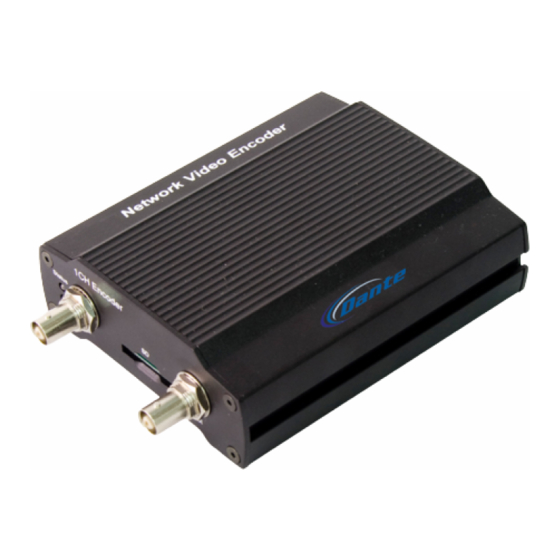
- Page 1 DN9131 H.264/MPEG4/MJPEG Video/Audio/Data 1 Channel Encoder/Server Dual Stream Installation and Operations Manual Model Numbers: DN9131-1, DN9131-4 Description: H.264/MPEG4/MJPEG Encoder/Server Dual Configurable Video Streams with duplex Audio, Data, Alarms...
-
Page 2: Table Of Contents
Table of Contents Table of Contents DN9131 IP Encoder/Server 1. Introduction 1.1. Features 2. Specifications 3. Installations and Operations 3.1 Package Content 3.2 Components 3.2.1 Front Panel 3.2.2 Rear Panel 3.3 Typical Connections 3.4 Serial Number / Mac Address 4. Operation Description 4.1. -
Page 3: Introduction
1. Introduction DN9131 compress video/audio data and transmit the compressed video, audio, data through the network in real time. DN9131 provides a high quality video image with limited bandwidth and storage capacity. These products are ideally suited for a widerange of surveillance and remote monitoring applications. -
Page 4: Specifications
2. Specifications DN9131 Product Specifications Digital Signal Processing: TI Encoder with Reset Function Video Impedance: BNC Composite Video Input 75 Ohm, BNC Looping Output Video Compression: H.264/MPEG4/MJPEG, Dual Stream, Configurable Video Resolution: D1, CIF, QCIF, QVGA, VGA Video Frame Rate:... -
Page 5: Installations And Operations
3. Installation and Configuration 3.1. Package contents The Package contains the following. Please make sure all listed items are included in the box. DN9131------------------------------------------------------1 12VDC Adaptor---------------------------------------------1 LAN Cable (Cross Type 1.5m)-----------------------------1 9 Pin Terminal Block---------------------------------------2 100-240VAC Power Cable----------------------------------1 DN9131 LAN Cable... -
Page 6: Components
3.2. Components 3.2.1. Front Panel Figure 1. Front Panel of DN9131 1 Video Input BNC Connector Vin It is mainly used for CCTV camera inputs. 2 Video Output BNC Connector Vout is composite video loop-out 3, 4 Indicator LED (Status, Data) Status and Data indicators display the following system information. -
Page 7: Rear Panel
Figure 2. Rear Panel of DN9131 1 USB Port DN9131 provides one USB port which may connect to the USB device as an external storage device and a wireless device. It can be connected to multiple USB devices using USB HUB. - Page 8 Figure 3. Terminal block Audio Input DN9131 have one channel mono audio input. Audio Output DN9131 have one channel mono audio output. The audio output very low-watt, therefore it requires amplifier speaker (Do not use headphone /earphone directly) Digital Alarm Input (DI1, DI2) DN9131 supports two digital inputs.
- Page 9 Sensor 1 Sensor 2 Figure 4. Relay Type Digital Input Connection Please pay attention to electric characteristics during installation. Digital Alarm Output (DO1, DO2) DO devices can be connected as following Figure 5. LED 1 +12V LED 2 Figure 5. Digital Alarm Output Connection Please pay attention to electric characteristics during installation.
- Page 10 Figure 7. RS-232C Connection 3 LAN Connector (Ethernet) This is a RJ-45 LAN connector for 10/100 Base-T Ethernet. Figure 8. RJ-45 LAN connector 4 Power Adaptor Connector (DC 12V) DN9131 employs a 12VDC 1A adapter for input power. Figure 9. Power Connection...
-
Page 11: Typical Connections
5 LED Power Status Indicator 6 Reset Switch (Reset) Reset switch is used for restarting DN9131 or resetting DN9131 as Factory Default(FD). Refer to section 4.1 for detailed procedures. 3.3. Typical Connections SD memor Camera External Monitor Figure 10. DN9131’s Front Panel Connection... -
Page 12: Serial Number / Mac Address
3.4 Serial Number / MAC Address Serial number and MAC address is attached on the bottom of DN9131 as shown in Figure 12. 550012345 MAC Address 00:13:23:01:23:45 DN9131 P1331010100000-121 Serial Number Figure 12. Serial Number / MAC Address... -
Page 13: Operation Description
4. Operation Description 4.1. Factory Default Settings Factory default settings are set as follows: • IP address: 192.168.xx.yy (refer to 2.3 Serial Number / MAC Address) • Mask: 255.255.0.0 • Gateway: 192.168.0.1 • User ID: root • Password: pass xx yy xx yy MAC address = 00-13-23-01-23-45 →... -
Page 14: Power Over Ethernet (Poe)
5. Power over Ethernet (PoE) The PoE feature employed in DN9131 is available in model DN9131-4. The standard units for power via 12VDC are models DN9131-1. For the detailed information, please see Data Sheet on Series DN9131, 1 Channel Encoder/Server. -
Page 15: Electrical Characteristics
6. Electrical Characteristics 6.1. Operating conditions Parameters Typical Units Audio input range 0.01 2.593 Vp-p Ambient Operating Temperature ºC Ambient Operating Humidity Table 2. Operating conditions 6.2. Power consumption DN9131A Input Voltage 12VDC Current 120-240VAC Consumption 240mA Table 3. Power consumption Overvoltage and overcurrent will cause a severe damage to the device or even a fire. -
Page 16: Dimensions
7. Dimensions 141.4 121.7 37.7 103.4 1CH Encoder RS-232 Rx Tx DC12V Status Data Vout Reset Ethernet Aout RS-485 Revision history MANUAL# DATE(M/D/Y) COMMENTS D1A.01 02/09/09 Created D1A.02 02/1/09 Review and correct the error data... -
Page 17: Quick Guide To Changing Encoder Ip Address
QUICK GUIDE FOR UPDATING IP ENCODER DN9131 Factory default settings are set as follows: • IP address: 192.168.xx.yy (refer to 2.3 Serial Number / MAC Address) • Mask: 255.255.0.0 • Gateway: 192.168.0.1 • User ID: root • Password: pass xx yy xx yy MAC address = 00-13-23-01-23-45 →... - Page 18 9. In cmd prompt enter ping 192.168.35.69 (default IP address of DN9131) If not detected in Network a screen apperas as (Request timed out: 10.If detected in Network a screen appears as Reply from IP address – using example with 192.168.1.65 11.
- Page 19 15. Screen appears to indicate that the security of your PC is at risk 16. Select Continue to this website; open web browser of DN9131 Encoder 17. Click on Setup user name: root password: pass 18. If image vertical is jumping, select Video, Audio select Video-In 19.
- Page 20 22. Next ping device as in procedure # 9, if successful then 23. Use may open Internet explorer and type in new IP address selected 24. Screen appears to indicate that the security of your PC is at risk; Select Continue to this website; open web browser of DN9131 Encoder...
Need help?
Do you have a question about the DN9131 and is the answer not in the manual?
Questions and answers