
Related Manuals for MEN Mikro Elektronik A11

Summary of Contents for MEN Mikro Elektronik A11
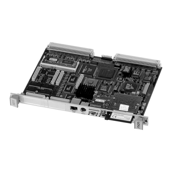
- Page 1 20A011-00 E4 - 2004-04-20 A11 – 6U VMEbus PowerPC Workstation User Manual Board-Level Computers for Industrial Applications ®...
- Page 2 The A11 offers computer I/O flexibility by providing two slots for PC•MIP mezzanine modules, while still providing full front-panel connectivity. Both Type I and Type II PC•MIP modules can be used to equip the A11 with a full range of workstation and industrial I/O options. Graphics for VGA, additional Ethernet or SCSI for server or redundancy purposes, fieldbus interfaces for remote I/O control, and many others are available, depending on the application.
-
Page 3: Technical Data
• 7-level interrupter • 7-level interrupt handler • System controller PC-MIP Mezzanine Extension • Two PC-MIPs Type I/II • On local PCI bus via DEC21150 PCI-to-PCI bridge • Compliant with PC-MIP specification MEN Mikro Elektronik GmbH 20A011-00 E4 - 2004-04-20... - Page 4 • Temperature range (storage): -40..+85°C • Relative humidity (operation): max. 95% non-condensing • Relative humidity (storage): max. 95% non-condensing • Altitude: -300m to + 3,000m • Shock: 15g/0.33ms, 6g/6ms • Vibration: 1g/5..2,000Hz MEN Mikro Elektronik GmbH 20A011-00 E4 - 2004-04-20...
- Page 5 • Tested according to EN 55022 / 1999-05 (radio disturbance) and EN 55024 / 1999-05 (immunity) with regard to CE conformity Software Support • MENMON • VxWorks • QNX • OS-9 MEN Mikro Elektronik GmbH 20A011-00 E4 - 2004-04-20...
- Page 6 COM1/2 Enhanced Parallel Ethernet 10/100Base-T 21143 Local Rear I/O Adapter AD39 Ultra2 SCSI SYM53C885 PCI Expansion PC•MIP Type II PCI-to-PCI Bridge 21150 PC•MIP Type II PCI-to-VMEbus Bridge Tundra Universe II VME64 Interface MEN Mikro Elektronik GmbH 20A011-00 E4 - 2004-04-20...
- Page 7 1.5A Fast 1206 Ethernet P2 interface For component locations, see Figure 21, Component Plan of A11 Hardware Revision 03 — Bottom Side, on page 106. Electrostatic Discharge (ESD) Computer boards and components contain electrostatic sensitive devices. Electrostatic discharge (ESD) can damage components. To protect the board and other components against damage from static electricity, you should follow some precautions whenever you work on your computer.
-
Page 8: About This Document
"in" meaning "to the board or component", "out" meaning "coming from it". Vertical lines on the outer margin signal technical changes to the previous edition of the document. MEN Mikro Elektronik GmbH 20A011-00 E4 - 2004-04-20... - Page 9 MEN will not be liable for any consequential or incidental damages arising from reliance on the accuracy of this document. The information contained herein is subject to change without notice. Copyright © 2004 MEN Mikro Elektronik GmbH. All rights reserved. Please recycle Germany...
-
Page 10: Table Of Contents
2.7.3 SCSI Termination on A11......32 2.8 PCI Expansion ......... . . 33 2.9 PC•MIP Slots. - Page 11 3.2 Console ..........57 3.3 A11 MENMON Memory Map ......58 3.4 MENMON Start-up .
- Page 12 5.3 Component Plans........105 MEN Mikro Elektronik GmbH...
- Page 13 Figure 4. SCSI Termination on A11 ........
- Page 14 Table 8. SCSI Termination on A11 ........32 Table 9.
- Page 15 Table 49. Table of Hardware Revisions ....... 102 MEN Mikro Elektronik GmbH...
-
Page 16: Getting Started
Getting Started Getting Started This chapter will give an overview of the A11 and some hints for first installation in a VMEbus system as a "check list". Map of the Board Figure 1. Map of the Board - Front Panel and Top View... -
Page 17: Configuring The Hardware
The following check list will give an overview on what you might want to configure. DRAM SO-DIMM modules The A11 is shipped with 32MB DRAM on board. You should check on your main memory needs and install a suitable SO-DIMM module if necessary. -
Page 18: Integrating The Board Into A System
Getting Started Integrating the Board into a System The A11 is a complex board and setting it up requires experience. You can use the following check list when installing the CPU board in a VMEbus system for the first time and with minimum configuration. -
Page 19: Installing Operating System Software
Getting Started The terminal displays the following message: ___________________ Secondary MenMon for the A11 Version 3.0 ________________ (c) 1998 - 2000 MEN mikro elektronik GmbH Nuernberg Parts of this code are based on Motorola’s Dink32 Created Feb 11 2000 13:42:19 |_____________________________________________________________________________| HW Revision: 01.01.00... -
Page 20: Functional Description
Resources on page 100). Power Supply The A11 is supplied with +5V via the VMEbus. However, PC•MIPs, PCI expansion cards or rear I/O adapters may need +12V. Two power supplies generate different supply voltages on the board: One is used for the PowerPC core voltage, which is factory-set for the corresponding processor. -
Page 21: Powerpc Cpu
Heat Sink A heat sink is provided to meet thermal requirements. Note: MEN gives no warranty on functionality and reliability of the A11 if you use any other processor or heat sink than that supplied by MEN. Please contact either MEN directly or your local MEN sales office! -
Page 22: Bus Structure
ISA interrupts. 2.4.4 PCI-to-PCI Bridge The A11 has a secondary PCI bus for PC•MIP mezzanines. It is controlled by a 21150 device and has a signaling voltage of 3.3V. 2.4.5... -
Page 23: Memory
MPC106 host bridge. 2.5.2 SDRAM Two SDRAM banks are implemented on A11. Bank 0 with 32MB is permanently mounted. Bank 1 is connected to a 144-pin SO-DIMM connector for easy extension. The MPC106 can handle SDRAM devices with up to 64Mbit. -
Page 24: Flash
MEN. Note: MEN gives no warranty on functionality and reliability of the A11 if you use any other module than that qualified and/or supplied by MEN. Please contact either MEN directly or your local MEN sales office. -
Page 25: Ethernet Interface
Differential pair of receive data lines TX+/- Differential pair of transmit data lines The A11 also features a 10Base-5 interface for rear I/O via a rear I/O adapter at VMEbus P2. (See also Chapter 2.21.2.3 Connecting a Rear I/O Adapter to P2 on page 54 and MEN’s... -
Page 26: General
Cables in the 10Base-T system connect with RJ45 connectors. A star topology is common with 12 or more computers connected directly to a hub or concentrator. The 10Base-T system operates at 10Mbps and uses baseband transmission methods. MEN Mikro Elektronik GmbH 20A011-00 E4 - 2004-04-20... -
Page 27: 100Base-T
100Base-T, including: • 100Base-TX: two pairs of high-quality twisted-pair wires • 100Base-T4: four pairs of normal-quality twisted-pair wires • 100Base-FX: fiber optic cables MEN Mikro Elektronik GmbH 20A011-00 E4 - 2004-04-20... -
Page 28: Scsi Interface
Select device, differential pair TERMPWR Termination power The A11 also supports two SCSI interfaces for rear I/O via a rear I/O adapter at VMEbus P2. (See also Chapter 2.21.2.3 Connecting a Rear I/O Adapter to P2 on page 54 and MEN’s... -
Page 29: Table 6. Pin Assignment Of The 68-Pin Vhdci Scsi Connector
TERMPWR TERMPWR DIFFSENSE SDP-[0] 14 SDP+/GND[0] SD-[7] SD+/GND[7] SD-[6] SD+/GND[6] SD-[5] SD+/GND[5] SD-[4] SD+/GND[4] SD-[3] SD+/GND[3] SD-[2] SD+/GND[2] SD-[1] SD+/GND[1] SD-[0] SD+/GND[0] SDP-[1] SDP+/GND[1] SD-[15] SD+/GND[15] SD-[14] SD+/GND[14] SD-[13] SD+/GND[13] SD-[12] SD+/GND[12] MEN Mikro Elektronik GmbH 20A011-00 E4 - 2004-04-20... -
Page 30: General
SE SCSI interfaces. Power consumption of LVD devices is reduced compared to a conventional differential bus through improvements in receiver design that permit reductions in steady-state current consumption and signaling voltage. MEN Mikro Elektronik GmbH 20A011-00 E4 - 2004-04-20... -
Page 31: Table 7. Overview Of Scsi Types, Maximum Bus Widths, Throughput And Line
16 bits 40 MB/s Wide Ultra SCSI 16 bits 40 MB/s 1.5m Wide Ultra SCSI 16 bits 40 MB/s Ultra2 SCSI 8 bits 40 MB/s Wide Ultra2 SCSI 16 bits 80 MB/s MEN Mikro Elektronik GmbH 20A011-00 E4 - 2004-04-20... -
Page 32: Scsi Termination On A11
2.7.3 SCSI Termination on A11 The A11 can be located in the "middle" of the SCSI bus or at its end. You must make sure the board is terminated properly for any case. As mentioned above, the A11 provides active termination, which can be configured as needed through MENMON. -
Page 33: Pci Expansion
Functional Description PCI Expansion The A11’s PCI expansion slot allows for various expansions at the PCI bus, e.g. using expansion cards for PMC or PC•MIP mezzanines. Different expansion boards are in preparation. Connector types: • 114-pin matched impedance receptacle connector, MICTOR .025 [0.64] center- line •... -
Page 34: Table 9. Pin Assignment Of The 114-Pin Pci Expansion Connector
Reserved RST# C/BE1# C/BE0# C/BE3# C/BE2# AD11 AD10 AD13 AD12 AD15 AD14 AD17 AD16 AD19 AD18 AD21 AD20 AD23 AD22 AD25 AD24 AD27 AD26 AD29 AD28 AD31 AD30 77..113 Reserved 78..114 Reserved MEN Mikro Elektronik GmbH 20A011-00 E4 - 2004-04-20... -
Page 35: Pc•Mip Slots
The A11 has two PC•MIP slots for Type-I and Type-II modules. Interfacing between the local 5V PCI bus and the 3.3V PC•MIP PCI bus is done using a DEC21150 PCI-to-PCI bridge. The PC•MIP slots enable the user to add functionality to the A11 CPU board, from graphics to process I/O. 2.9.1 Installing PC•MIPs... -
Page 36: Pc•Mip Connectors
P1 and P2. The connector layout is fully compatible to the PC•MIP specification and will not be repeated here. Although the A11 has a third, identical 64-pin connector (P3), it does not support rear I/O connection. Connector types of P1, P2 and P3: •... -
Page 37: Compactflash
The CompactFlash standard is supported by industry’s leading vendors of Flash cards. You can use CompactFlash cards with the A11 through the AD35 adapter, which is accessible at the front panel. The adapter is connected using a board-to-board connector. The AD35 configures CompactFlash cards in a True IDE Mode of operation. -
Page 38: Keyboard/Mouse
Table 11. Signal Mnemonics for Keyboard/Mouse Interface Signal Direction Function KB_GND Keyboard logic ground KB_VCC Keyboard +5V supply, max. DC current 200mA KBCLK Keyboard clock KBDAT Keyboard data MSECLKDAT Mouse clock MSEDAT Mouse data MEN Mikro Elektronik GmbH 20A011-00 E4 - 2004-04-20... -
Page 39: Serial Ports Com1/Com2
Receive data Transmit data The A11 also supports COM1 and COM2 at VMEbus P2 for rear I/O via a rear I/O adapter. The signal level is fixed to TTL at the rear. This allows flexible line interface configuration using serial interface (SA) adapters. (See also Chapter 2.21.2.3 Connecting a Rear I/O Adapter to P2 on page 54... -
Page 40: Asynchronous/Synchronous Serial Ports Com3/Com4
Functional Description 2.13 Asynchronous/Synchronous Serial Ports COM3/COM4 The A11 uses the Zilog Z85230 ESCC (Enhanced Serial Communications Controller) to implement two serial communications interfaces—COM3 and COM4. COM3 is prepared for asynchronous protocols and COM4 for synchronous protocols such as SDLC or HDLC. The ports are accessible only via VMEbus P2 via a rear I/O adapter. -
Page 41: Enhanced Parallel Port
2.14 Enhanced Parallel Port The enhanced parallel port of the A11 is connected to the VMEbus P2 connector for rear I/O via a rear I/O adapter. It supports ECP, EPP, PS/2, SPP and 1284 compliance. The port includes a protection circuit against damage caused when a printer is powered up or operated at higher voltages. -
Page 42: Floppy Disk Controller
• mating connector: 26-pin ZIF plug, 1mm pitch, for FPC/FFC connection Table 15. Pin Assignment of 26-pin ZIF Floppy Disk Drive Connector INDEX# SEL0# CHANGE# DENSEL MOTON# DIR# STEP# WDATA# WGATE# TRK0# RDATA# HDSEL# MEN Mikro Elektronik GmbH 20A011-00 E4 - 2004-04-20... -
Page 43: Table 16. Signal Mnemonics For Floppy Disk Drive Connector
DIR# Direction Digital ground HDSEL# Head select INDEX# Index MOTON# Motor on RDATA# Read data SEL0# Drive select 0 STEP# Step TRK0# Track 0 WDATA# Write data WGATE# Write gate Write protect MEN Mikro Elektronik GmbH 20A011-00 E4 - 2004-04-20... -
Page 44: Hardware Monitor
2.17 Timekeeper, NVRAM and Watchdog The A11 includes the M48T59Y 64Kbit timekeeper NVRAM with watchdog. A snaphat top with battery and oscillator guarantees a typical data retention of 10 years at 25°C. The M48T59 checks its battery voltage at power-up. An internal control bit is set at power-up if the battery voltage is below 2.5V (typical). -
Page 45: Reset/Abort Buttons And User/Status Leds
CPU: CPU activity; lights when the DBB# (Data Bus Busy) sig- nal line on the processor bus is active CHS: checkstop; driven by the PowerPC; lights when a halt condition from the processor is detected MEN Mikro Elektronik GmbH 20A011-00 E4 - 2004-04-20... -
Page 46: User-Defined Hex Switch
Functional Description 2.20 User-Defined Hex Switch The A11 provides a rotary hex switch for operating system requirements and user applications. Please refer to the corresponding software manual for the implemention. Figure 10. Position of Hex Switch SO-DIMM DRAM Socket PC•MIP Bezel Keepers PC•MIP slot 2... -
Page 47: Vmebus Interface
The Tundra Universe II becomes VMEbus master when it is requested by the PCI bus. In this case it acts as a PCI target device. The A11 supports all addressing and data transfer modes documented in the VME64 specification (except A64) including read-modify-write and address-only cycles. -
Page 48: Figure 11. Vmebus Interrupts
Functional Description 2.21.1.4 VMEbus Interrupt Handler The A11 is able to handle all seven VMEbus interrupts. The interrupts may be masked and enabled in the Tundra Universe II register set (cf. Chapter 4.2 Interrupt Handling on page 94). The Tundra Universe II generates a single PCI interrupt with the LINT0 on the INTB line. -
Page 49: Connection
• 160-pin, 5-row plug, performance level according to DIN41612, part 5 • Mating connector: 160-pin, 5-row receptacle, performance level according to DIN41612, part 5 Note: Connector rows Z and D are only present with 5-row VMEbus models of the A11! MEN Mikro Elektronik GmbH 20A011-00 E4 - 2004-04-20... -
Page 50: Table 19. Pin Assignment Of The 5/3-Row, 96/160-Pin Vmebus Connector P1
BG3IN# SYSFAIL# GA0# BG3OUT# BERR# GA1# DS1# BR0# SYSRESET# DS0# BR1# LWORD# GA2# WRITE# BR2# BR3# GA3# DTACK# GA4# IACK# IACKIN# IACKOUT# IRQ7# IRQ6# IRQ5# IRQ4# IRQ3# IRQ2# IRQ1# -12V VSTBY +12V MEN Mikro Elektronik GmbH 20A011-00 E4 - 2004-04-20... -
Page 51: Table 20. Pin Assignment Of The 5/3-Row, 96/160-Pin Vmebus Connector P2
RxD4 V_D[27] CTS1 RTS4 V_D[28] TxD2 TRxC4 V_D[29] RxD2 CTS4 V_D[30] RTS2 DTR4 V_D[31] CTS2 DCD4 TERMPWR RTxC4 DIFFSENSE Note: The pin assignment of P2 is compatible with Motorola’s MVME712M transition module. MEN Mikro Elektronik GmbH 20A011-00 E4 - 2004-04-20... -
Page 52: Table 21. Signal Mnemonics Of Vmebus Rear I/O Connector P2
Request SRST# in/out Bus reset SSEL# in/out Select device TERMPWR power Termination power CTS1 COM1 clear to send RTS1 COM1 request to send RxD1 COM1 receive data TxD1 COM1 transmit data MEN Mikro Elektronik GmbH 20A011-00 E4 - 2004-04-20... - Page 53 COM4 clear to send DCD4 COM4 data carrier detect DTR4 COM4 data terminal ready RTS4 COM4 request to send RTxC4 COM4 receive clock RxD4 COM4 receive data TRxC4 COM4 transmit clock TxD4 COM4 transmit data MEN Mikro Elektronik GmbH 20A011-00 E4 - 2004-04-20...
-
Page 54: Figure 12. Connection Of A Rear I/O Adapter (E.g. Men's Ad39)
Functional Description 2.21.2.3 Connecting a Rear I/O Adapter to P2 You can connect a rear I/O adapter to the VMEbus P2 connector of the A11 through a VMEbus backplane. Adapters with a 3-row VMEbus connector can also be connected directly to P2. See MEN’s website for I/O adapters available from MEN. -
Page 55: Ieee 1149.1 (Jtag)/Cop Test Interface
2.22 IEEE 1149.1 (JTAG)/COP Test Interface The A11 provides IEEE 1149.1 and COP functions for facilitating board testing and chip debug. The IEEE 1149.1 test interface provides a means for boundary-scan testing of the PowerPC CPU and the board to which it is attached. The COP function shares the IEEE 1149.1 test port, provides a means for executing test... -
Page 56: Configuring The Ieee 1149.1 Test Interface
1 2 3 2.22.2 Configuring the COP Test Interface To use the COP test interface, you need to change three resistors on the A11’s bottom side as shown in the following figure. Figure 14. Resistors for COP Test Interface C462... -
Page 57: Menmon
• a VGA adapter could be found and • a PS/2 keyboard could be found. Currently, the A11 supports MEN’s P1 PC•MIP module (either with the SMI910 or SMI710 chip). VGA console operates in standard VGA mode (i.e. 640x480 pixels, white on black, 60 Hz). -
Page 58: A11 Menmon Memory Map
MENMON A11 MENMON Memory Map Figure 15. MENMON — Address Mapping 0x 0000 0000 Exception Wrappers 12KB 0x 0000 3000 MENMON Parameter String 512 bytes 0x 0000 3200 Unused 0x 0000 4200 VxWorks Bootline 256 bytes 0x 0000 4600 Unused... -
Page 59: Menmon Start-Up
MENMON performs these commands until one of the commands passes control to a loaded image. The "EE-STARTUP -" command can be used to deactivate autoexecution of the string. When the string is inactive, MENMON calls its BO command at start-up. MEN Mikro Elektronik GmbH 20A011-00 E4 - 2004-04-20... -
Page 60: Self Tests
=== HEX === GPI 0 ==> 0 DOCK ==> 1 GPI 2 ==> 1 GPI 3 ==> 1 HEX-SW ==> 0x1 OK === FLASH === CHECKSUM ==> OK *** ERROR at selftest MEN Mikro Elektronik GmbH 20A011-00 E4 - 2004-04-20... - Page 61 The test is not performed during Power On Self Test. This test does not check the ABORT interrupt. This test enters and displays the A11 clock configuration. The test is not performed during Power On Self Test. An error is detected for unknown PLL configuration for the installed CPU type.
-
Page 62: Menmon Boot Methods For Client Programs
====== [ Device Table ] ========= CLUN DLUN Device Type Handle 0x00 0x00 SunDisk SDCFB-20 IDE HD 0x000FFCA0 0x01 0x00 IBM DDRS-34560D SCSI HD 0x000FFC50 0x02 0x00 Std FDC Floppy Std Floppy 0x000FFC10 MEN Mikro Elektronik GmbH 20A011-00 E4 - 2004-04-20... -
Page 63: Table 23. Menmon - Assignment For A11 Controller Devices
0x00 .. 0x0F ) and for any other PCI device that is supported by the MENMON drivers. If additional controllers are found on the PCI bus, they receive CLUNs ≥ 0x10 . Table 23. MENMON — Assignment for A11 Controller Devices CLUN Controller... -
Page 64: Disk Boot
Entry Point Offset (LE) Load Image Length (LE) Load Image Flag Field OS_ID Partition Name Reserved1 1023 OS-Specific Field (optional) Entry Point (Code Code Section of the Load Image Aligned) Reserved2 RBA_Count x 512 MEN Mikro Elektronik GmbH 20A011-00 E4 - 2004-04-20... -
Page 65: Figure 18. Menmon - Single Boot-Image Cd-Rom Configuration
When MENMON detects such a CD-ROM format, it handles the contained bootable disk image like a standard hard or floppy disk, i. e. the same boot algorithm is performed as for normal floppy and hard disks. MEN Mikro Elektronik GmbH 20A011-00 E4 - 2004-04-20... - Page 66 Regardless of the file format, the entire boot file will be loaded to MENMON’s download area ( 0x01000000 ). (This address can be overridden using the LOAD parameter.) The load address must not be between 0x01F00000 and 0x01FFFFFF . MEN Mikro Elektronik GmbH 20A011-00 E4 - 2004-04-20...
- Page 67 • R1 is set to the top of runaway stack - 512 bytes. • R3 is set to 0 (no residual data available). • R4 is set to the image loading address. (Not the relocation address!) • R5..R7 are cleared. MEN Mikro Elektronik GmbH 20A011-00 E4 - 2004-04-20...
- Page 68 DBOOT 0 0 PART=2 • Load file MYBOOT from SCSI hard disk with ID 2 DBOOT 1 20 FILE=MYBOOT • Try to find a bootable device on the SCSI bus: DBOOT 1 MEN Mikro Elektronik GmbH 20A011-00 E4 - 2004-04-20...
- Page 69 • In case of problems you can try to read raw sectors from disk using the DSKRD command. • Use the EE-STARTUP command to perform the DBOOT command automati- cally at startup. MEN Mikro Elektronik GmbH 20A011-00 E4 - 2004-04-20...
-
Page 70: Network Boot
If you intend to boot via BOOTP, the host computer must also set up a table (usually called bootptab) containing an entry for each target system to be booted. An entry in bootptab for A11 could look like this: mysystem:sm=255.255.255.0:\ hd=/usr/TFTPBOOT:\... -
Page 71: Menmon Tape Boot
Ethernet Medium Selection MENMON currently supports Ethernet controllers using the DEC21xxx chips. These chips can be found onboard the A11, on the P3 and P12 PC•MIP mezzanines and on some other PCI hardware. The medium to be used (10Mbit or 100Mbit, full duplex or half duplex) is stored in the SROM that is connected to the DEC chip. -
Page 72: Updating Flash Devices
When a file is larger than one sector, the following sector of the device will also be programmed. The update file is transferred to DRAM before being programmed to Flash. The DRAM of the A11 must therefore be large enough for the entire download file. The update file may be max. 15MB. MEN Mikro Elektronik GmbH... -
Page 73: Performing The Download
0xFF0000 3.6.2 Performing the Download You must connect your host to A11's COM1 interface. Before you start the download, change the MENMON console baudrate to 115,200 baud (enter EE-BAUD 115200 and reset A11). To start download enter SERDL in the MENMON command line. You must specifiy... -
Page 74: Update From Disk Or Network
It is also possible to program Flash with a file from a disk or network: Load the file into memory: DBOOT HALT=1 NBOOT HALT=1 Program the Flash (in this case OS bootstrapper): PFLASH F 0 100000 This programs the first Mbyte of Flash. MEN Mikro Elektronik GmbH 20A011-00 E4 - 2004-04-20... -
Page 75: Menmon User Interface
Some of the addresses used in our examples may not be suitable for your board’s address mapping. If you want to try out MENMON’s functions, please compare the example addresses with your mapping first! MEN Mikro Elektronik GmbH 20A011-00 E4 - 2004-04-20... -
Page 76: Menmon Command Overview
DSKRD <args> Read blocks from RAW disk DSKWR <args> Write blocks to RAW disk BIOS_DBG <mask> Set MMBIOS debug level I [<D>] List A11 information EE[-xxx] [<arg>] Serial EEPROM commands VME[-xxx] [<arg>] VME contr. parameters in EEPROM DIAG [<arg>] System diagnosis SERDL [<passwd>]... - Page 77 MENMON Command Description PCI-VPD[-] <devNo> [<busNo>] [<capId>] PCI Vital Product Data dump PCI probe Reset board MEN Mikro Elektronik GmbH 20A011-00 E4 - 2004-04-20...
-
Page 78: Board Setup
• USB 3.8.2 PCI Auto-Configuration MENMON maps all detected PCI devices to PCI memory and PCI I/O space. PCI bus masters are enabled. PCI bus interrupts are routed and configured in configuration space. MEN Mikro Elektronik GmbH 20A011-00 E4 - 2004-04-20... - Page 79 • PCI-VPD Shows the "vital product data" on devices that support it. Note: Since the A11 is running with PowerPC Address Map A, you must add 0x C000 0000 to any PCI memory address and 0x 8000 0000 to PCI...
-
Page 80: Vmebus
System Controller (Slot-1) Function The slot-1 function (clock generation and arbiter) is enabled automatically when the A11 is plugged into slot 1 of the VME rack. Whether the function is enabled or not is displayed during MENMON's startup procedure: Init VME Controller.. (Slot 1 function enabled) 3.8.3.2... -
Page 81: Scsi
• EE-SCSI-TERM8 Controls the terminator for SCSI bus signals D0..D7 and common control lines. It must be enabled when the A11 SCSI controller is at the end of the SCSI cable. • EE-SCSI-TERM16 Controls the terminator for the upper half of SCSI bus (wide SCSI) •... -
Page 82: Menmon System Calls
Parameters are passed and returned in registers R3 to Rn, where n is less than10. ADDI R10,R0,$XXXX $XXXX is the 16-bit code for the system call routine, and SC is the system call instruction (system call to the debugger). Register R10 is set to 0x0000XXXX . MEN Mikro Elektronik GmbH 20A011-00 E4 - 2004-04-20... -
Page 83: System Calls
Exit Conditions R03: Address Starting address of ID packet different from (word) Entry Note: CLUN and DLUN are initialized according to the device that was last booted (for example, DBOOT or NBOOT command). MEN Mikro Elektronik GmbH 20A011-00 E4 - 2004-04-20... - Page 84 R03: Bit 3 (ne) = 1; Bit 2 (eq) = 0 if the receiver buffer is not different from empty. Entry R03: Bit 3 (ne) = 0; Bit 2 (eq) = 1 if the receiver buffer is empty. MEN Mikro Elektronik GmbH 20A011-00 E4 - 2004-04-20...
-
Page 85: Table 31. Menmon - System Calls - Rtc_Rd Buffer Data
Seconds (2 nibbles packed BCD) Entry R03: Buffer address where RTC data is to be returned Conditions Exit Conditions Buffer now contains date and time in packed BCD format. different from Entry MEN Mikro Elektronik GmbH 20A011-00 E4 - 2004-04-20... -
Page 86: Table 32. Menmon - System Calls - Dsk_Rd Fields
VMEbus address modifier to use while transfer- fier ring data. If zero, a default value is selected by the debugger. If nonzero, the specified value is used. Entry R03: 32-bit address of command packet Conditions MEN Mikro Elektronik GmbH 20A011-00 E4 - 2004-04-20... - Page 87 R03: Bit 3 (ne) = 1; Bit 2 (eq) = 0 if errors. R03: Bit 3 (ne) = 0; Bit 2 (eq) = 1 if no errors. Note: MENMON’s internal status codes are returned in Status. MEN Mikro Elektronik GmbH 20A011-00 E4 - 2004-04-20...
-
Page 88: Vxworks Bootline
(g=) IP address of gateway EE-NETGW Yes, for NBOOT user (u=) User name ftp password (pw=) Password flags (f=) Flags for VxWorks target name (tn=) Name of this machine EE-NETNAME MEN Mikro Elektronik GmbH 20A011-00 E4 - 2004-04-20... -
Page 89: Additional Menmon Parameters
656D303D 33323736 s=COM1 mem0=3276 00003050: 38206370 753D4D50 43373430 20637075 8 cpu=MPC740 cpu 00003060: 636C6B3D 32393920 6D656D63 6C6B3D36 clk=299 memclk=6 00003070: 37206C32 63616368 653D3531 3220766D 7 l2cache=512 vm 00003080: 65697271 656E623D 46450000 93810020 eirqenb=FE..MEN Mikro Elektronik GmbH 20A011-00 E4 - 2004-04-20... -
Page 90: Organization Of The Board
Organization of the Board Organization of the Board To install software on the A11 board or to develop low-level software it is essential to be familiar with the board’s address and interrupt organization. Memory Mappings The memory mapping of the A11 complies with the PowerPC Reference Platform (PRP) Specification. -
Page 91: Pci Configuration Space Map (Primary Bus)
0x80900100..0x80FFFFFF 0x00900100..0x00FFFFFF Reserved 4.1.3 PCI Configuration Space Map (Secondary Bus) Table 37. PCI Configuration Space Map (Secondary Bus) IDSEL CPU Address PCI Configuration Space Address Definition Tbd. Tbd. PC•MIP 0 Tbd. Tbd. PC•MIP 1 MEN Mikro Elektronik GmbH 20A011-00 E4 - 2004-04-20... -
Page 92: Pci/Isa I/O Space Memory Map
IDE Primary registers part B 0x800003F8..0x800003FF M1543 Super I/O UART1 controller 0x8000040B M1543 DMA1 Extended Mode Register 0x80000481..0x8000048B M1543 DMA High Page Registers 0x800004D0 M1543 INT_1 (master) Edge/Level Control 0x800004D1 M1543 INT_2 (slave) Edge/Level Control MEN Mikro Elektronik GmbH 20A011-00 E4 - 2004-04-20... -
Page 93: Vmebus Memory Map
Address Modifiers 0x8C000000..0x8CFEFFFF A24/D16 0x8CFF0000..0x8CFFFFFF A16/D16 0x8D000000..0x8DFEFFFF A24/D16 0x8DFF0000..0x8DFFFFFF A16/D16 0x8E000000..0x8EFEFFFF A24/D32 0x8EFF0000..0x8EFFFFFF A16/D32 0x8F000000..0x8FFEFFFF A24/D32 0x8FFF0000..0x8FFFFFFF A16/D32 0xC0000000..0xC7FFFFFF A32/D16 0xC8000000..0xCFFFFFFF A32/D32 Legend (address modifiers) D Data P Program U User S Supervisor MEN Mikro Elektronik GmbH 20A011-00 E4 - 2004-04-20... -
Page 94: Interrupt Handling
Organization of the Board Interrupt Handling The A11 supports both maskable and nonmaskable Interrupts. The interrupt controller is located inside the M1543 PCI-to-ISA bridge. Figure 19. A11 Interrupt Structure MPC106 MCP# PowerPC IRQ0 Counter M1543 LM78 IRQ5 IRQ1 Keyboard IRQ2... -
Page 95: Nonmaskable Interrupts
INTA INTD INTA INTB INTB INTA INTB INTC INTC INTB INTC INTD INTC INTD The entire interrupt routing is managed by the boot software and board support package of the operating system. MEN Mikro Elektronik GmbH 20A011-00 E4 - 2004-04-20... -
Page 96: Implementation Of Sym53C895 Scsi Controller
Organization of the Board Implementation of SYM53C895 SCSI Controller The A11 provides the terminators for SE and LVD mode. Mode setting and termination is handled by the general purpose pins of the SYM53C895 SCSI controller. Table 43. General-Purpose Pins of SYM53C895 SCSI Controller... -
Page 97: Implementation Of M1543 Pci-To-Isa Bridge
Organization of the Board Implementation of M1543 PCI-to-ISA Bridge The GPO/GPI/GPIO pins of the M1543 are used for several functions on the A11. The tables below show the port assignments of the A11. There are 10 General Purpose Output pins, 6 General Purpose Input pins and 8 General Purpose I/O pins. -
Page 98: Table 46. M1543 General Purpose Output Pin Assignments
The on-board hex switch is connected to the general purpose inputs of the M1543. Table 47. M1543 GPI Assignment for Hex Switch M1543 Description GPI 0 Switch bit 1 DOCK Switch bit 2 GPI 2 Switch bit 4 GPI 3 Switch bit 8 MEN Mikro Elektronik GmbH 20A011-00 E4 - 2004-04-20... -
Page 99: Z8536 Cio
C bus SCL out C bus VME64 geographic address DTRB Data terminal ready port B ABORT Status of the abort button VME64 geographic address VME64 geographic address VME64 geographic address VME64 geographic address MEN Mikro Elektronik GmbH 20A011-00 E4 - 2004-04-20... -
Page 100: Appendix
- The VMEbus Handbook, Wade D.Peterson, 1989 VMEbus International Trade Association www.vita.com 5.1.3 • PCI Local Bus Specification Revision 2.1: 1995; PCI Special Interest Group P.O. Box 14070 Portland, OR 97214, USA www.pcisig.com MEN Mikro Elektronik GmbH 20A011-00 E4 - 2004-04-20... -
Page 101: Ethernet
Global Engineering Documents 2805 McGaw Irvine, CA 92714 5.1.6 Parallel Port • Parallel Port (EPP): 1284-1994 IEEE Standard Signaling Method for a Bidirectional Parallel Periph- eral Interface for Personal Computers; 1994; IEEE www.ieee.org MEN Mikro Elektronik GmbH 20A011-00 E4 - 2004-04-20... -
Page 102: Pc•Mip
1. Operating temperature The operating temperature range is limited to 0°C..+60°C. We recommend to guarantee suffi- cient air flow inside the rack. The A11 uses 8T in a rack. 2. Reset operation Onboard reset operations are not directed to the VMEbus, except PowerON Reset. - Page 103 Workaround: Connect an open cable to the RJ45 port. 3. Reset button The A11 enters the standby mode after the reset button is pressed for 5 seconds. When the button is pressed again, the board re-enters the normal mode.
- Page 104 Workaround: Connect an open cable to the RJ45 port. 3. Reset button The A11 enters the standby mode after the reset button is pressed for 5 seconds. When the button is pressed again, the board re-enters the normal mode.
-
Page 105: Component Plans
Appendix Component Plans Figure 20. Component Plan of A11 Hardware Revision 03 — Top Side IC17 IC76 R122 R129 NR39 IC71 IC18 IC89 IC80 C354 C303 IC79 IC77 IC74 IC81 IC72 GND1 IC65 IC66 IC78 IC67 IC88 C1004 IC31 IC83... -
Page 106: Figure 21. Component Plan Of A11 Hardware Revision 03 - Bottom Side
Appendix Figure 21. Component Plan of A11 Hardware Revision 03 — Bottom Side C145 C353 C301 C146 C464 C195 R135 C249 C251 C117 C119 C155 C118 C120 R1007 C135 IC59 IC58 IC57 IC56 C326 C170 C157 C194 C192 C456 R136... - Page 107 MEN reserves the right to refuse sending of confidential information for any reason that MEN may consi- der substantial. Non-Disclosure Agreement for Circuit Diagrams provided by MEN Mikro Elektronik GmbH between MEN Mikro Elektronik GmbH Neuwieder Straße 7 D-90411 Nürnberg...
- Page 108 Amendments to this Agreement can be adopted only in writing. There are no supplementary oral agree- ments. This Agreement shall be governed by German Law. MEN Mikro Elektronik GmbH The court of jurisdiction shall be Nuremberg. Neuwieder Straße 5-7 90411 Nürnberg Deutschland Tel.
Need help?
Do you have a question about the A11 and is the answer not in the manual?
Questions and answers