Advertisement
Quick Links
LUXOMAT
Installation and Operating Instruction for B.E.G. - Occupancy detectors PD3-1C-SM/-FC/-FM and PD3-2C-FC/-FM
1. Mounting preparations
Work on the 230 V mains supply
may only be carried out by qualified
professionals or by instructed persons
under the direction and supervision
of qualified skilled electrical person-
nel in accordance with electrotechni-
cal regulations.
Disconnect supply before installing!
3. Putting into operation / Settings
Follow-up time for device control (PD3-2C)
40
50
30
60
15
The time can be set infinitely variably at between
90
10
5 and 120 minutes.
120
5
mins
120 60 50
A
Follow-up time for light control
40
30
secs
1
min
TEST
30
The time can be set infinitely variably at between
2
4
15
5
10
30 seconds and 30 minutes.
6
8
12
Symbol
:
impulse < 1sec.
30
mins
TEST
Symbol
: Test mode
16 10
5
(Every movement switches on the light for a period of
2
2000
1
1 second, switching it off for a period of 2 seconds
1200
TEST
30
15
600
after that regardless of the level of brightness.)
200
40
Twilight-switch for light control
2000
1200
The switch-on value for the light can be set at
600
between 10 and 2000 Lux. Using the rotary control,
200
40
the luminance set points can be set as desired.
Symbol :
Night-time operation
Symbol
:
Daytime / Night-time operation
Adjusting sensitivity (PD3-1C)
max.
For sensitivity adjustment of the detector, both in the
interior and the exterior range, the PD3-1C-SM/-FC
min.
is equipped with an additional knob (see pictures)
for excluding sources of interference, e.g. bad
weather conditions or draught air.
Max:
for interior use
(recognition of the slightest movements)
Min:
for exterior use
(exclusion of sources of interference)
Sound (PD3-1C-Micro)
max.
Max:
highest sensitivity
Min:
microphone switched off
min.
Intermediate values to be adjusted accordingly to
local conditions. Lighting of the LED means the noise-
detector is functioning and triggers the timer again.
The microphone is active for 9 seconds after the last
movement and time delay completed.
6. Range of Coverage
2.50 m
1
1
walking across
quer zum Melder gehen
2
frontal zum Melder gehen
walking towards
seated
Unterkriechschutz
®
2a. Installation of the LUXO-
MAT
PD3-SM
®
The detector must be in-
stalled on a solid and level
surface. There is no need
for frames.
For mounting remove lens
(C) (turn anticlockwise).
Fasten the mounting base
to the ceiling.
Having connected up the wires in accordance
with regulations, secure the detector with 2
screws as per the illustration above.
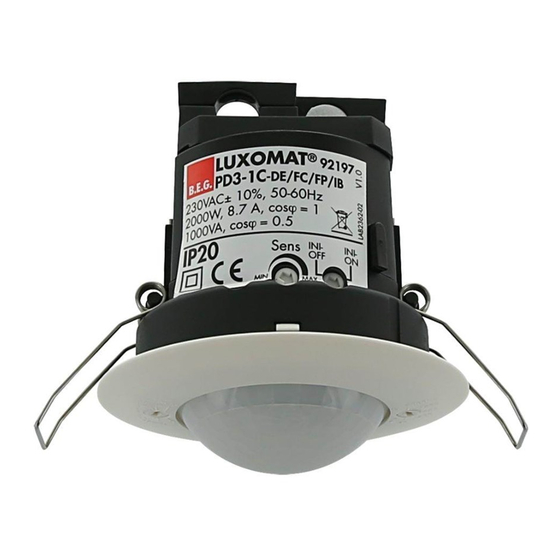
4. Technical data PD3
Sensor and power supply in one case
Power supply: 230 V~ +6 %/-10 %
Power consumption: < 1W
Ambient temperature: -25°C to +50°C
Degree of protection /class: SM IP54, FC and FM IP20,
FC with accessory IP23 / II
Settings: locally
Area of coverage: circular 360°
Range of coverage Ø H 2.50 m / T = 18°C:
seated 2.50 m / tangential 10 m / radial 6 m
Recommended height for mounting: 2 - 3 m
Light measurement: mixed light, daylight + artificial light
Lux values - Potentiometer: 10 - 2000 Lux
• Channel 1 for light-connection
Type of contact: NOC/with pretravel tungsten contact
Contact load: 2000 W, 230 V~, cos (ϕ) =1 /
1000 VA cos (ϕ) = 0.5
Time-settings: 30 sec. - 30 min. / Test
• Channel 2 for HVAC (only PD3-2C)
Contact load: 230 V~, 3 A cos (ϕ) =1
Time-settings: 5 min. - 120 min. with time delay of 5 min.
for follow-up time > 15 min.
Dimensions H x Ø [mm]
PD3
Visible portion when built into ceiling: 34 x 74 mm
Declaration of Conformity: The product complies with
the low voltage recommendation 2006/95/EC and the
EMV recommendation 2004/108/EC.
2
PD3-1C(-Micro)/-2C
2b. Installation of the LUXO-
MAT
PD3-FC
®
e.g. 65 mm
The detector has
been designed
and developed
specifically for instal-
lation in suspended
ceilings.
A circular opening of
diameter 65 mm must
be cut into ceiling.
Having connected up the cables in accor-
dance with regulations, the detector is
inserted into the opening as shown in the
drawing above and fixed into position with
the assistance of the spring clips.
SM
FC
52 x 106 84,5 x 80 65 x 98
2c. Installation of the LUXO-
MAT
PD3-FM
®
5. Trouble shooting
1. Lamp does not light up
Lamp may be defect:
Replace lamps
No mains connection/power:
Check connection and mains fuse by qualified electrician
Incorrect setting of CDS twilight threshold:
Correct setting of CDS threshold
Lens of sensor unit obstructed by dirt or other objects:
Clean lens, remove objects
2. Lamp turns ON too late or detection range too small
LUXOMAT
PD3 is mounted too high:
®
See table of mounting heights.
Correct mounting if required.
3. Lamp stays ON continuously
Continuous thermal activity detected ie fan, central heat-
ing ducts, animals within detection area:
Remove heatsource. Check proper function of LUXOMAT
PD3 by covering the fresnel-lens. After expiry of delay
timer, PD3 has to turn OFF lighting.
FM
LUXOMAT
PD3 connected in parallel to a manual over-
®
ride switch:
Connect switch correctly
4. Unintended switching of light
Movement of heat source within detection area:
Check on presence of animals, fans or heaters
7. Article / Part nr. / Accessory
Type
PD3-1C
PD3-1C-Micro
PD3-2C
Accessory:
BSK Ball basket guard
FC-Covering IP23
SM-Blinds
GB
The detector can be installed
in conventional inlet-sockets
mounted on the ceiling.
The assembly plate enclosed
must be stripped off prior to
installation and secured to the
ceiling using 4 screws.
Having connected up the
cables in accordance with
regulations, the detector
can be placed in position
as shown in the drawing
opposite and, applying a little
pressure, can then be locked
into position with the assist-
ance of the spring clips.
®
SM
FC
FM
92190
92196
92186
92219
92184
–
–
92198
92188
92199
92206
92260
Advertisement

Related Manuals for B.E.G. LUXOMAT PD3-1C


Summary of Contents for B.E.G. LUXOMAT PD3-1C
- Page 1 PD3-1C(-Micro)/-2C LUXOMAT ® Installation and Operating Instruction for B.E.G. - Occupancy detectors PD3-1C-SM/-FC/-FM and PD3-2C-FC/-FM 1. Mounting preparations 2a. Installation of the LUXO- 2b. Installation of the LUXO- 2c. Installation of the LUXO- PD3-SM PD3-FC PD3-FM ® ® ® Work on the 230 V mains supply The detector must be in- e.g.
- Page 2 PD3-FM Terminal connection for parallel-operation PD3-2C-FC 48x48 R L' N L L NO NO 230VAC Slave / 50-60Hz contact Remote R L' N L Circuit like PD3-1C-FC, but additional with two dry contact (relay 2).