
Related Manuals for LAWO ruby


Summary of Contents for LAWO ruby
- Page 1 User Manual Version: 6.0.0/4 Edition: 18 January 2018 To obtain the latest documentation and software downloads, please visit: www.lawo.com/downloads...
- Page 2 All rights reserved. Permission to reprint or electronically reproduce any document or graphic in whole or in part for any reason is expressly prohibited, unless prior written consent is obtained from the Lawo AG. All trademarks and registered trademarks belong to their respective owners. It cannot be guaranteed that all product names, products, trademarks, requisitions, regulations, guidelines, specifications and norms are free from trade mark rights of third parties.
-
Page 3: Table Of Contents
VCA Grouping .......................... 45 Pool & RAVENNA Sources ....................... 47 Working with Layers ......................... 50 5.10 Fader Mappings ........................52 5.11 Configurable Surface Functions ....................53 5.12 Snapshots ..........................55 5.13 The SYS Menu ......................... 58 ruby User Manual Version: 6.0.0/4 3/82... - Page 4 Solving Connectivity Issues ......................73 8. Appendices ............................74 Part Numbers ........................... 75 Dimension Drawings ......................... 76 Connector Pin-Outs ........................77 The 12V DC Power Supply ......................78 The User Labels Software ......................79 4/82 Version: 6.0.0/4 ruby User Manual...
-
Page 5: Introduction
Welcome to ruby. About this Manual This document describes all aspects of the ruby control surface, including its hardware components, installation, connections, operation and maintenance. The specification is valid for Version 6.0.0.x. The surface requires a DSP Core such as POWER CORE and, optionally, may run with a VisTool MK2 touch- screen interface. -
Page 6: Important Safety Instructions
This equipment may use Class 1 Laser products which emit invisible laser radiation that may lead to eye injury. · NEVER look directly into optical components or optical fibre cables. · Fit protection caps to close any unused optical components. · Connect all optical fibre cables BEFORE turning on the equipment. 6/82 Version: 6.0.0/4 ruby User Manual... - Page 7 Defective Parts/Modules Warning ruby contains no user-serviceable parts. Therefore DO NOT open the devices other than to perform the procedures described in this manual. In the event of a hardware defect, please send the system component to your local service representative together with a detailed description of the fault.
-
Page 8: The Hardware
3. The Hardware The Hardware This chapter describes the system components, controls, options and accessories. Topics include: · System Components · DSP Core Compatibility · Controls Overview · Control Surface Variants · Placement Options · Accessories 8/82 Version: 6.0.0/4 ruby User Manual... -
Page 9: System Components
3. The Hardware System Components A complete system consists of up to four components: · ruby Control Surface (essential) – available in single or split-frame configurations. · DSP Core (essential) – all audio interfacing, routing, control and signal processing. ·... -
Page 10: Dsp Core Compatibility
3. The Hardware DSP Core Compatibility The ruby control surface is compatible with the following DSP Core products: 10/82 Version: 6.0.0/4 ruby User Manual... -
Page 11: Controls Overview
The upper section includes a rotary control and four small MF Keys (1, 1a, 2, 2b). Their functions are labeled by the OLED displays. There are then three large MF Keys (3, 4, 5) with foil-printed labels. All MF Keys are defined by the configuration. ruby User Manual Version: 6.0.0/4 11/82... - Page 12 Function Buttons are NOT supported. This means that there is no access to DSP parameters, bus assign, system options and snapshots. All controls are defined by the configuration. Note that the 12 Function Buttons cannot be programmed by the configuration and, therefore, will remain blank. 12/82 Version: 6.0.0/4 ruby User Manual...
- Page 13 If you change the MF Key functionality, then you will need to exchange the foil-printed labels. Printed sheets with the most common labels are included with each control surface frame. ruby User Manual Version: 6.0.0/4 13/82...
-
Page 14: Control Surface Variants
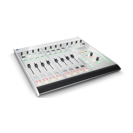
8-fader single frame 12-fader split-frame ruby can exist as a single or multi-frame control surface. A choice of four main and five extender frames are available. Frames can be combined to increase the fader count or create a split-frame surface. Each frame connects to the DSP Core via CAN bus, and is powered from its own 12V DC power supply (included). - Page 15 CAN bus is wired after the Assistant's station. Multi-frame Configuration A single control surface can support up to 60 faders, a single Central Module and up to 6 monitor mode Central Modules. ruby User Manual Version: 6.0.0/4 15/82...
-
Page 16: Placement Options
· Countersunk Short - the same as Countersunk but with shorter side profiles and no upper cover plate to hide the cables (i.e. the rear panel connectors will be visible). 16/82 Version: 6.0.0/4 ruby User Manual... -
Page 17: Accessories
Printed sheets with a selection of foil printed labels - to label the MF Keys. If your control surface consists of multiple frames, then you will receive one set of accessories per frame (as every frame requires its own power, CAN bus and MF Key labels). ruby User Manual Version: 6.0.0/4 17/82... -
Page 18: Installation
This chapter describes how to install the control surface. Topics include: · Preparation · Installing Countersunk Frames · Wiring · Working with the CAN Bus · CAN Bus Addressing · Powering the Device · Exchanging the MF Key Labels 18/82 Version: 6.0.0/4 ruby User Manual... -
Page 19: Preparation
Please check the contents of the shipping boxes, and in the event of any transport damage, contact your local Lawo representative or email support@lawo.com. Please take note of the Technical Data label, which includes your serial number, located on the underside of each frame. -
Page 20: Installing Countersunk Frames
All countersunk frames have flat side parts without edges. Therefore, the installer must provide some kind of support onto which the surface will rest. Please see the dimension drawings for details. 20/82 Version: 6.0.0/4 ruby User Manual... -
Page 21: Wiring
Connect the 12V DC power supply to the DC IN connector on the frame. Using the IEC cable provided, connect your AC mains to the external power supply. WARNING: The control surface frame MUST be connected to the mains using the power cable supplied with the system. ruby User Manual Version: 6.0.0/4 21/82... - Page 22 Every frame is delivered with a suitable cable. Cabling The following instructions describe how to connect a ruby control surface to the DSP Core. Note that all connections MUST be point-to-point; a switch or hub is not allowed. The control surface can be hot-plugged via CAN, and so the cabling can be performed while the frames are powered.
-
Page 23: Working With The Can Bus
Now is a good time to check and, if necessary, adjust the CAN bus address and CAN speed settings for each control surface module and Key Panel. A CAN speed of 500 kbit/sec is recommended. ruby User Manual Version: 6.0.0/4... -
Page 24: Can Bus Addressing
Address 12 to 17 (hexadecimal) can be assigned to additional Central Modules (in monitor mode). Frame -> Surface: ruby 4+1 CAN Bus Addresses (hexadecimal) Each address must be unique, so do not assign the same address to more than one module. If you do so, this can lead to control conflicts and odd behaviour of the surface. - Page 25 Central Module (Address 10); and which frames include monitor mode Central Modules (if applicable). Frame -> Surface menu: ruby 15 + 1 +6 Example Control Surface Layers (Fader Mappings) Each Fader Module supports two layers.
-
Page 26: Powering The Device
Then, open one of the standard configurations (included in the ON-AIR Designer) or build your own. Use the "Transfer Config -> Unit" function to load the configuration onto the DSP Core. These procedures are described in the manual for your DSP Core. 26/82 Version: 6.0.0/4 ruby User Manual... -
Page 27: Exchanging The Mf Key Labels
Insert the foil plate between the button body and the transparent button cap. Fasten the button cap back onto the button body by pressing it! Remove Button Cap Insert Printed Foil Label Exchange Complete ruby User Manual Version: 6.0.0/4 27/82... -
Page 28: Operation
DSP Parameter Control · Bus Assign · Conference Bussing (Mix Minus/N-1) · VCA Grouping · Pool & RAVENNA Sources · Working with Layers · Fader Mappings · Configurable Surface Functions · Snapshots · The SYS Menu 28/82 Version: 6.0.0/4 ruby User Manual... -
Page 29: The Fader Strip
VisTool MK2 or the User Labels software. MF Keys 3 & 4 The two large MF keys are programmed by the configuration and are defined per source. In our example, they are channel ON and PFL ruby User Manual Version: 6.0.0/4 29/82... - Page 30 LFE – low frequency effect level, from -120 to +9 dB. Front/rear pan, slope and LFE level are only available if a surround bus is configured on your console and surround parameters are enabled on the source. 30/82 Version: 6.0.0/4 ruby User Manual...
- Page 31 In the configuration, use the Source Color and Source Color Mode options (in the Source or Sum Bus branch of the 'Tree Definition') to define the colour coding and mode of operation. The signal present thresholds are defined globally (in System -> Definition -> Parameter = Signal Present). ruby User Manual Version: 6.0.0/4 31/82...
- Page 32 User labels are configured globally from the System -> Definition -> Param = Fader branch of the 'Tree Definiton'. There are options to set the mode (on, off or toggle) and text size (small or large). 32/82 Version: 6.0.0/4 ruby User Manual...
- Page 33 The last User Labels are stored in the console's warm start data. This means that when you power on you will get back to wherever you were when the power was last turned off! ruby User Manual Version: 6.0.0/4 33/82...
- Page 34 As an alternative to VisTool MK2, you can use the dedicated User Labels Software. This must be installed on an external computer connected to the system network. See the User Labels Software for details. 34/82 Version: 6.0.0/4 ruby User Manual...
-
Page 35: The Central Module(S)
The parameter value and button functions are shown in the OLED. MF Keys 45 & 46 These two MF Keys are programmed by the configuration. On consoles with more than one layer, they usually provide global layer switching. ruby User Manual Version: 6.0.0/4 35/82... - Page 36 Note that the 12 "Function Buttons" are not supported and cannot be programmed. Therefore, they will remain unused. In the configuration, use the Surface -> Central Module (monitor mode) branch of the 'Tree Defintion' to define the functionality. 36/82 Version: 6.0.0/4 ruby User Manual...
-
Page 37: Assigning Fader Strips
If the fader label does not update, then the assignment has failed. This may occur if you have reached the limit of source sums supported by the DSP resources. ruby User Manual Version: 6.0.0/4 37/82... - Page 38 In the configuration, if the global Save Value option is NOT selected, then you must close the fader before you can enter "source assign" mode. Press the Remv MF Key - the current source is removed leaving a blank fader strip. 38/82 Version: 6.0.0/4 ruby User Manual...
-
Page 39: Dsp Parameter Control
Only one source, or summing bus, can be in access at a time. If you have an external VisTool MK2 display, then you may be able to view the parameters graphically. See the "VisTool MK2 User Guide". ruby User Manual Version: 6.0.0/4 39/82... - Page 40 (e.g. Frequency). When you have finished adjusting all parameters, deselect the white ACCESS key on the fader strip - the Central Module rotary controls and small MF keys return to their default mode of operation. 40/82 Version: 6.0.0/4 ruby User Manual...
-
Page 41: Bus Assign
0dB unless operating in special circumstances. Otherwise you will not achieve unity gain through the console. You may be able to adjust send levels from the faders if an MF Key or other control trigger has been programmed to access this function. ruby User Manual Version: 6.0.0/4 41/82... - Page 42 When you have completed all your assignments, deselect the BUS function button to return the fader strip MF Keys and rotary controls to their default functions - the BUS button remains half lit when deselected: Default Functionality 42/82 Version: 6.0.0/4 ruby User Manual...
-
Page 43: Conference Bussing (Mix Minus/N-1)
Close all three source faders. The CONF buttons become red and all sources will hear the conference bus minus themselves. In other words, they can hear each other, but not themselves, and chat off-air. ruby User Manual Version: 6.0.0/4 43/82... - Page 44 CONF button. To cancel the conference for any of the sources, deselect the CONF button. The CONF buttons turn green (off) and the source’s monitor feed receives programme minus themselves at all times. 44/82 Version: 6.0.0/4 ruby User Manual...
-
Page 45: Vca Grouping
In the configuration, use the Display name and Source Color options (in the Source -> Parm branch of the 'Tree Definition') to edit these options. ruby User Manual Version: 6.0.0/4 45/82... - Page 46 If you do not see the combined level in the slave fader displays, then this option is not configured. In the configuration, use the Show Group Fader Values option (in the System -> Definition -> Param = Fader branch of the 'Tree Definition') to enable this feature. 46/82 Version: 6.0.0/4 ruby User Manual...
-
Page 47: Pool & Ravenna Sources
– in our example, the pool source labeled Pool 1. Select the source and press Take to assign it to the fader strip. In our example, this has assigned Pool Source 1 which is the first stereo MADI tie line from our Nova73. ruby User Manual Version: 6.0.0/4 47/82... - Page 48 -> -> -> "Mute" ("Pending") "Tuning" ("Unstable") "<Stream-Name>" Note that messages shown in () may or may not appear. The table on the next page explains the meaning of each message in more detail. 48/82 Version: 6.0.0/4 ruby User Manual...
- Page 49 Since the flags are updated cyclically, the error should heal itself. If the issue persists, then check the RAVENNA pages (in the Web UI). The audio input will be muted while the error message is displayed. ruby User Manual Version: 6.0.0/4 49/82...
-
Page 50: Working With Layers
All open sources are active in the mix. This means that if you switch to Layer 2, open a fader and then switch back to Layer 1, audio may still be passing even though all visible faders are closed! 50/82 Version: 6.0.0/4 ruby User Manual... - Page 51 In the configuration, use the Global Switch to Layer 1/Layer 2 options (in the System -> Definition -> Parameter = Fader branch of the 'Tree Definition') to programme the LAYER 1 and LAYER 2 MF Keys. ruby User Manual Version: 6.0.0/4...
-
Page 52: Fader Mappings
In the configuration, use the Channel Mappings tab (in the Surface -> Fader Module branch of the 'Tree Definition') to configure fader mappings. 52/82 Version: 6.0.0/4 ruby User Manual... -
Page 53: Configurable Surface Functions
If you require additional metering, then VisTool MK2 can provide configurable metering pages on an external monitor connect to the VisTool runtime PC. Please see the "VisTool MK2 User Guide" for details. VisTool MK2 Example ruby User Manual Version: 6.0.0/4 53/82... - Page 54 MF Key. · Plus many other functions. GPIO functionality is defined by the configuration. In the configuration, use the GPI/O branch in the 'Tree Definition' to program GPIO parameters. 54/82 Version: 6.0.0/4 ruby User Manual...
-
Page 55: Snapshots
· System -> Definition -> Parameter = Logic Snapshot - defines which logical states are stored. · System -> Definition -> Parameter = Matrix Snapshot - defines which matrix connections are stored. ruby User Manual Version: 6.0.0/4 55/82... - Page 56 The SNAP LOAD button flashes magenta to indicate a successful operation, and the console’s settings update accordingly. WARNING: It is not recommended that snapshots are loaded during a live broadcast, as to do so may result in sources being taken off air! 56/82 Version: 6.0.0/4 ruby User Manual...
- Page 57 Keep pressing and holding while you select a memory number – e.g. press 4. The snapshot memory is erased. To check the erase has worked, press and hold SNAP LOAD. The memory should now be clear (unlit): ruby User Manual Version: 6.0.0/4 57/82...
-
Page 58: The Sys Menu
Use this option if you wish to position the fader (e.g. at 0dB) and then turn on the channel instantly (by pressing channel ON or deselecting the MUTE button). 58/82 Version: 6.0.0/4 ruby User Manual... - Page 59 PFL bus. Multiple AFLs may be summed. AFL is only cancelled by deselecting the AFL button. · AFL/PFL - as for AFL, but the channel's PFL signal is heard when the fader is closed; when the fader opens, the listen bus receives AFL. ruby User Manual Version: 6.0.0/4 59/82...
-
Page 60: Maintenance
This chapter describes the maintenance procedures for the control surface frames and components. Topics include: · Checking the Hardware Status · Updating Firmware · The Special Functions Mode · Replacing Defective Parts · Locating the Control Surface Serial Number · Cleaning the Control Surface 60/82 Version: 6.0.0/4 ruby User Manual... -
Page 61: Checking The Hardware Status
In the example above, the system has detected four Fader Modules and one Central Module. A further three Fader Modules are configured, but either they are not fitted or their frame is not connected. For more details about the Web UI, please refer to your DSP Core manual. ruby User Manual Version: 6.0.0/4 61/82... -
Page 62: Updating Firmware
The current revision of each system component (Surface, System and IOs) can be checked and, if necessary, updated by transferring files from a networked computer. Full details on how to use the tool can be found in your DSP Core manual. 62/82 Version: 6.0.0/4 ruby User Manual... -
Page 63: The Special Functions Mode
The keys on the module can now be used to adjust system settings (CAN speed and frame ID) and to test the module components (Keys, LEDs, Faders and Rotary encoders). At this stage, the keys have no function as they are protected by the Unlock key. ruby User Manual Version: 6.0.0/4 63/82... - Page 64 Alternatively, to exit any menu without making a change, or to exit a test, press and hold Unlock and Exit. Once have you finished working in the “special functions” mode, repower the control surface frame to return the module to normal operation. 64/82 Version: 6.0.0/4 ruby User Manual...
- Page 65 Settings and tests are performed in a similar manner as on a Fader Module. When running the Key Test, the value of the ambient light sensor is displayed as a binary encoded value through the colouring of the keys T37 to T41. ruby User Manual Version: 6.0.0/4 65/82...
- Page 66 T23 = Frame ID Bit 2 · T31 = Frame ID Bit 1 · T32 = Frame ID Bit 0 (LSB) The Frame_ID (CAN bus address) should be set to match the Frame layout defined in the configuration. 66/82 Version: 6.0.0/4 ruby User Manual...
- Page 67 6.3.6 Self Test This test is an automated test which checks all the key and LAWO display LEDs. Enter the Self Test and all LAWO displays and keys, except Unlock, with flash in yellow. 6.3.7 Fader-Calibrate This test calibrates the module’s motorised faders. This operation should be performed after replacing a fader, or after around 2 year’s operation.
- Page 68 To reset the colour so that all keys return to their default unlit state: Select the menu again by pressing Unlock and RGB Def. The key T2 is unlit. And press Unlock and Exit. 68/82 Version: 6.0.0/4 ruby User Manual...
-
Page 69: Replacing Defective Parts
This allows fast replacement of a frame in the case of a hardware failure. Providing the replacement frame is set to the correct CAN bus addresses, it will immediately take over the same functions as the exchanged frame. ruby User Manual Version: 6.0.0/4 69/82... -
Page 70: Locating The Control Surface Serial Number
The serial number of your control surface can be found on the product information sticker placed on the underside of the panel: Sticker Location The S/N field indicates the Serial Number: Product Information Sticker 70/82 Version: 6.0.0/4 ruby User Manual... -
Page 71: Cleaning The Control Surface
To clean the control surface please use a cleaning cloth with the following properties: · Antistatic · Fluff-free · Without emery pieces Warning DO NOT spill liquids into any system components! DO NOT clean the mixing console with sharp instruments! ruby User Manual Version: 6.0.0/4 71/82... -
Page 72: Trouble-Shooting
7. Trouble-shooting Trouble-shooting This chapter includes a series of typical problems and tips to help you fault find the system. Topics include: · Solving Connectivity Issues 72/82 Version: 6.0.0/4 ruby User Manual... -
Page 73: Solving Connectivity Issues
This can occur if the same CAN bus address is used for more than one module. Check the CAN bus addresses of each module using the special functions mode. Each address must be unique and match the one defined by the configuration. See CAN Bus Addressing. ruby User Manual Version: 6.0.0/4 73/82... -
Page 74: Appendices
8. Appendices Appendices This chapter includes further information which you may find useful. Topics include: · Part Numbers · Dimension Drawings · Connector Pin-Outs · The 12V DC Power Supply · The User Labels Software 74/82 Version: 6.0.0/4 ruby User Manual... -
Page 75: Part Numbers
12-fader table top RU12FTT ruby 16-fader table top RU16FTT ruby 4-fader Extender table top RU4FEXTT ruby 8 fader Extender table top RU4FEXTT ruby 12-fader Extender table top RU12FEXTT ruby 16-fader Extender table top RU16FEXTT ruby Central Module Extender table top... -
Page 76: Dimension Drawings
8. Appendices Dimension Drawings Please use the links below to open the dimension drawing as a pdf: · Ruby Desk Table Top Dimension Drawing · Ruby Desk Countersink STD Dimension Drawing · Ruby Desk Countersink Short Dimension Drawing The drawings show an 8-fader main frame. -
Page 77: Connector Pin-Outs
8. Appendices Connector Pin-Outs 8.3.1 8-pin RJ45 connector, female. 8.3.2 DC Power Input 4-pin Kycon connector, female. ruby User Manual Version: 6.0.0/4 77/82... -
Page 78: The 12V Dc Power Supply
Weight Cable length without plug 1200 Electrical Specification Parameter Conditions Min. Typ. Max. Unit Input Voltage Frequency Input Current 1,85A/115VAC 1A/230VAC Inrush Current 120A/230VAC Efficiency Output Voltage 12±5% Output Current 11.5 Leakage Current 0,75 78/82 Version: 6.0.0/4 ruby User Manual... -
Page 79: The User Labels Software
The DSP Core MUST be running OS Version 3.4.0.17a software or higher. You can check the OS version using the Web Browser Interface (click on Supplementary Information). If the OS-Version is lower than 3.4.0.17a, please contact your local Lawo representative or email support@lawo.com. - Page 80 8. Appendices If you have any problems with the installation, please contact your local Lawo representative or email support@lawo.com. 8.5.3 Network Connection You should connect the User Labels PC to the DSP Core's Ethernet port either directly or via a network switch.
- Page 81 User labels for all source and busses in the configuration are saved when you save a snapshot. This means that you can save and recall labels for specific shows along with other settings, see Snapshots. ruby User Manual Version: 6.0.0/4...
- Page 82 Identifier - displays the internal System Number. This number cannot be modified and is for information only. o Font... - select to open the Font dialogue box. You can use this to adjust the on-screen font for the user labels table. 82/82 Version: 6.0.0/4 ruby User Manual...
Need help?
Do you have a question about the ruby and is the answer not in the manual?
Questions and answers