Table of Contents
Advertisement
Quick Links
Advertisement
Table of Contents

Related Manuals for Holley EFI

Summary of Contents for Holley EFI
- Page 1 Holley EFI Digital Dash User Manual...
-
Page 2: Table Of Contents
CONTENTS Introduction ............................4 Quick Start Guide ..........................5 Package Contents ..........................5 Specifications ............................5 General ................................5 Mounting ................................ 6 Connectors ..............................7 CAN1/Power ............................... 7 USB ................................7 CAN Adapter Harness ..........................7 Using the Dash ............................. 8 Touchscreen Basics ............................ - Page 3 USB Flash Drive Removal ........................33 Utilities Menu ............................33 Global Config ............................... 33 Downloading the Current EFI Configuration....................34 Uploading a New EFI Configuration ......................34 Deleting EFI configuration files ......................... 34 File Utilities ..............................34 Backup/Restore ............................35 Security Settings ............................
-
Page 4: Introduction
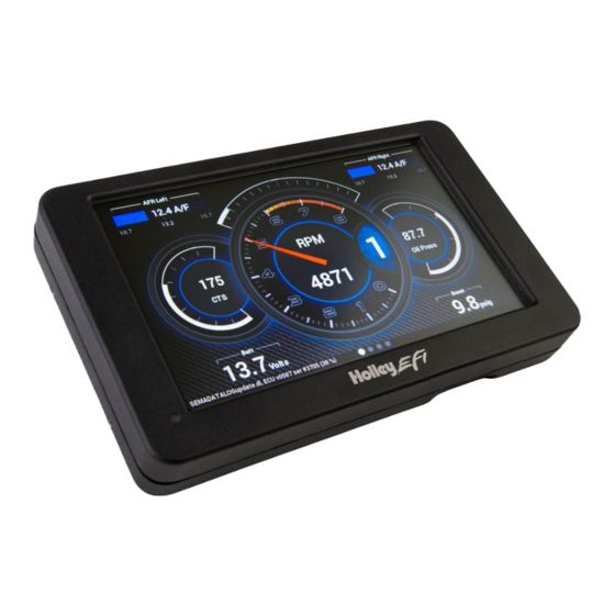
The Dash features a 7" low glare, high brightness, high contrast, full color touch screen for easy viewing even in full sun, plug and play connection to all Holley EFI systems as well as a weather proof aluminum housing featuring flexible mounting options. Monitor the power of... -
Page 5: Quick Start Guide
Connect the harness from the CAN connector on the vehicles main harness to the digital dash using the supplied 4’ CAN/Power extension Once all connections have been made the Holley EFI Digital Dash may be powered up. After a brief initial loading sequence the gauge display will appear. -
Page 6: Mounting
Mounting The product has eight tapped 8-32 mounting holes to allow the user to surface mount or flush mount the enclosure. There are four mounting holes located on the rear of the unit, and two mounting holes are located on the left and right sides. Included with the contents of this kit is a separate template with a 1:1 layout of the hole locations for fabricating a mounting bracket. -
Page 7: Connectors
Connectors CAN1/Power 4 pin Mizu-P25 male receptacle connector used to connect main power and to a Holley EFI. The dual connector allows the product to be connected to multiple devices on the CAN bus. Function Color Description +12V Main power in... -
Page 8: Using The Dash
Using the Dash Touchscreen Basics The Holley EFI Digital Dash has been designed with a resistive touchscreen, meaning it will work with bare skin, a stylus, or even through driving gloves. This dash responds to localized point pressure on the screen, not ‘swiping’, which is common on capacitive screens found on current smart phones and tablets. - Page 9 If you are using the Digital Dash without a Holley EFI, select Standalone mode. The EFI specific Datalog and Tuning buttons will no longer be shown in this mode.
- Page 10 Configures the inputs and outputs that are available using the 558-432, 558-433 or 558-434 I/O Adapter. Consult the I/O Adapter Instruction manual for more information on configuring the Local I/O tab. Pin refers the physical pin number on the I/O Adapter. CAN Devices Tab Configures CAN-connected devices such as the Holley 553-107 LED Light Bar.
- Page 11 Local Dash Speed Calculation area on the Holley Digital Dash. ECU Input: Use with a custom speed sensor input from the I/O section of your Holley ECU. The ECU input must be named “speed” and the units set to miles/hour for the odometer to report distance accurately.
-
Page 12: Dashboard
This selection returns you to the operational dash layout. Data Log The Holley EFI Digital Dash allows you to retrieve, delete and configure data logging with the attached HEFI. Data logs can be saved internally or to a USB memory stick for viewing on a computer. -
Page 13: Adding Gauges
Type. Once you have selected the gauge type you will be asked to select the value to monitor. Every available EFI channel including user configured inputs and outputs will be shown in this list (see Appendix A). Once the value is chosen the gauge will be placed on the screen. - Page 14 Symbol The symbol gauge type will change its color based on settings in the warnings section for this gauge. This can be used to display an automotive symbol warning light or normally hidden text that will be displayed when an alarm condition is reached.
- Page 15 Gauge Type Examples: ANALOG BARGRAPH DIGITAL METER STATUS LEDS AFR METER THIN ANALOG GRAPH RPM BAR...
-
Page 16: Customizing The Gauge
Customizing the Gauge While in ‘Customize’ mode, touch the gauge you would like to modify and a menu will appear. To move the gauge select ‘Move’ (A) and drag the gauge to place it in the desired location. To customize the visual properties and warning indicators, select ‘Customize’... - Page 17 Font Size This is used to adjust the font size of labels within the gauge. Touch inside the text box to bring up a number keypad. The top of the keypad will display the minimum and maximum text size values (in pixels). In this case, the minimum is 5 and maximum is 240.
- Page 18 Range This will adjust the minimum and maximum display range of the gauge. Warnings for Gauges Configuring warnings will dictate when the gauge changes colors. When values reach the Low Warning or High Warning value, the gauge face will change to the color beneath that value. When the gauge value reaches Low Alarm or High Alarm, the gauge face will change to the corresponding color.
- Page 19 Symbols are similar, which will change color based on its corresponding value channel. In this manner you can duplicate the function of lit symbols on your dashboard. Figure A. CTS Warning Example Status LEDs for Switched Items (ON/OFF) A status LED can be lit to show when an item is either on or off. To have an LED lit for when an item is turned on, configure per Figure B.
- Page 20 Full color configuration and Alpha control (transparency) can be used with Status LEDs. Touch the rectangular color bar below the value input box to change colors. Status LED Configuration Status LED Color Configuration Alpha Channel example from left to right (75, 150, 255)
- Page 21 Peak Hold Enabling the Peak Hold features will place a marker at the highest and/or lowest value for quick viewing. This feature is similar to the traditional ‘Tattletale’ Tachometers. The minimum peak is shown with a blue triangle, and the maximum peak is a red triangle. Gauge Sweep Users can configure the sweep angle of Analog and Thin Analog gauges.
- Page 22 Gauge Sweep Examples: -120 Start / 120 End 120 Start / -120 End -205 Start / 45 End 0 Start / 90 End Foreground Color Changing the foreground color will modify the text, labels and values of a gauge. Use a stylus to drag the crosshair to the desired color.
- Page 23 Background Color Changing the Background Color of a gauge is done following the same steps as the Foreground Color. The alpha channel controls the transparency of the background. Transparency The transparency of a gauge background can be modified to achieve your desired style. A value of 255 makes the gauge completely opaque, and a value of 0 makes the gauge completely transparent.
- Page 24 Precision Changing the precision of a gauge will show more or less decimal points after the whole number. Tachometers generally will not use any decimal places; however it may be beneficial to display fuel flow or AFR values with one or more decimal place. Segments Users can configure the number of segments on gauges.
- Page 25 Size Overall Gauge sizes can be adjusted by increasing or decreasing their pixel size. The minimum and maximum values are displayed near the top of the number keypad. In this case, the min is 20 and the max is 780. Value Display When Value Display is enabled, a digital meter will appear inside an analog gauge showing real time values in addition to the needle indicator.
-
Page 26: Adding Labels
Adding Switches Switches can be placed anywhere on the gauge screen, they can be used to turn devices on or off, as a nitrous enable, etc. These functions are mapped through the Holley EFI software. Follow these steps for proper configuration:... - Page 27 1. Create an input in the I/O screen and give it a name – for this example we have named it “SWITCH 1” 2. Create an output in the I/O screen and give it a name – in this example we have named them “Cooling Fan”, “Elec Water Pump”, and “NOS Bottle Htr”.
-
Page 28: Changing The Background
5. Select ‘View Outputs’ from the ‘Pin Map’ and drag the outputs to the whatever pin location the device was wired to. 6. You will have to send the new configuration to the EFI and toggle the ignition for approximately 5 seconds for the changes to be saved. Turn on the ignition to continue. -
Page 29: Saving Your Layout
To remove the background from the current layout, press Ok without selecting a filename. Saving Your Layout Once a layout has been created it must be saved. Touch any blank portion of the gauge screen and select Save. Exporting / Importing Layouts You can save a copy of your layout in Customize mode by touching on any blank portion of the gauge screen and select Layout >... -
Page 30: Start-Up Gauge Layout
3. Choose ‘Save’ in the top right corner of the gauge screen. Preconfigured Layouts The Holley EFI Digital Dash comes standard with ten preconfigured gauge layouts. The first four of these layouts are active by default. If a smaller or larger number of layouts are desired, select ‘Configuration’ from the Main Menu. - Page 31 Layout 5 Layout 6 Layout 7 Layout 8 Layout 9 Layout 10...
-
Page 32: Modifying Channels On A Preconfigured Layout
Data Log Record and Playback Local Data Record The Holley EFI Digital Dash has a record button that will record data logs directly to a USB flash drive or internal storage. The record button can be shown by pressing anywhere on the dashboard display. -
Page 33: Usb Flash Drive Removal
Press on the ‘X’ at the top left corner to return to the main menu. Global Config A global configuration contains the complete configuration of a Holley EFI in a single .hefi file. The Dash can upload and download global configs to the connect EFI. -
Page 34: Downloading The Current Efi Configuration
EFI configuration, and press Download to start the transfer. Uploading a New EFI Configuration To upload a new configuration to your Holley EFI, first ensure that the engine is not running. Navigate and select the desired .hefi configuration file and press Upload to ECU to start the transfer. -
Page 35: Backup/Restore
The Dash has the ability to lock out certain functionality. To disable a particular feature, place a checkmark beside the feature you wish to lock out. Default Password Before you can change any settings, you will need to enter the default password of “holley” (without quotes.) - Page 36 File utilities menu is disabled Backup/Restore Dash backup and restore functionality is disabled Standalone Choice The user cannot switch between standalone and EFI-connected mode. Dash Configuration The user cannot change the local dash channel configuration, can device configuration, vehicle settings, or touchscreen calibration.
-
Page 37: Efi Tuning
EFI Tuning The Digital Dash has been equipped to tune most of the EFI parameters. It is expected that the user is familiar with the PC tuning software and general EFI tuning principles. From the main menu, choose the Tuning menu to adjust most of the parameters in your Holley EFI. -
Page 38: Numeric Editor
Numeric Editor Selecting a parameter with a numeric value will bring up a numeric keypad and slider bar on the right half of the screen. You may use either the slider or keypad to change the value. The parameter limits are shown near the slider bar. -
Page 39: Graph Editor
Graph Editor Parameters that are graphical will bring up the graph editor. Graphs can be edited by selecting a point and dragging it up and down, or by clicking on the yellow value box near the point you wish to edit. Multi-series graphs have a selection on the right hand side to select the series you are editing. -
Page 40: Table Editor
Select Smooth or Interpolate then press Ok. To perform an action, select the desired function, type in a value and press Apply. Changes are not sent to the EFI until the ‘Save’ button is pressed. Function... -
Page 41: User Customizable Menus
User Customizable Menus You can change the title of the user customizable menu by pressing on the menu label for more than 2 seconds. A keyboard will appear allowing you to change the name of the menu. To add items to a user menu, you must first navigate to the desired item. Press on the desired menu item label for more than 2 seconds and a dialog box will appear allowing you to select which menu to add or remove this item to. -
Page 42: List Of Efi Monitored Values
List of EFI Monitored Values Below is a list of 283 values that can be monitored. Any user programmed I/O values will appear in the list in addition to these once the Dash has been connected to a Holley ECU. INJ PW1... - Page 43 TIMING RETARD #2 CYL TIMING CORR13 N2O TIMING MOD7 ADV AT 2D/GEAR 3 TIMING RETARD #3 CYL TIMING CORR14 N2O MTIMING MOD8 ADV AT 2D/GEAR 4 FAN #1 CYL TIMING CORR15 N2O TIMER1 ADV AT 2D/GEAR 5 FAN #2 CYL TIMING CORR16 N2O TIMER2 ADV AT 2D/GEAR 6 #2 FUEL PUMP...
-
Page 44: Increasing Internal Logging Storage (Micro-Sd Card)
Appendix B Increasing Internal Logging Storage (micro-SD card) To increase the storage space for internal logging, you may purchase a micro-SD card and install it inside the unit. Please turn off power to the unit before opening the access panel. Using a Philips screwdriver, carefully remove the rear access panel. -
Page 45: Optional I/O Connector
Figure 4. Flip door down Figure 5. Slide door to the right to lock Optional I/O Connector The internal I/O connector can be used for stand-alone applications or as additional inputs and outputs. An optional I/O adapter is available as part number 558-432, 558-433 or 558-434. IO10 SSR GND switched output (2A) 5V Input... -
Page 46: Appendix C
Appendix C The following preloaded background images can be found in /internal/images. LAYOUT1 LAYOUT2 LAYOUT3 LAYOUT4 LAYOUT5 LAYOUT6... - Page 47 LAYOUT7 LAYOUT8 LAYOUT9 LAYOUT10 Holley_EFI_1 Holley_EFI_2 BlackStone Fire2 3_gauge_dark_lt_blue 3_gauge_dark_orange...
- Page 48 3_gauge_dark_pink 3_gauge_dark_purple 3_gauge_dark_red 3_gauge_dark_teal 3_gauge_dark_yellow 3_gauge_dark_green 3_gauge_blue 3_gauge_red...
- Page 49 3_gauge_lt_blue 3_gauge_lt_green 3_gauge_green 3_gauge_orange 3_gauge_pink 3_gauge_purple 3_gauge_teal 3_gauge_yellow...
- Page 50 2_gauge_black 3_gauge_black Check out the collection of fuel systems we offer.
Need help?
Do you have a question about the EFI and is the answer not in the manual?
Questions and answers